Note: Descriptions are shown in the official language in which they were submitted.
211~88
~ack~round and summary
This invention relates to pressure washers, and, more
particularly, to a pressure washer which is equipped with a flow
control switch for shutting off power to the pressure washer if
fluid is not flowing through the pressure washer.
Pressure washers are well known devices for delivering
water or other washing fluid under high pressure, e.g., about
1200 to 2000 psi. Pressure washers conventionally include a
pump assembly which includes a plurality of pumping pistons
which are driven by an electric motor or an internal combustion
motor. Fluid is commonly supplied to the pump by a garden
hose. Pressure washers of this type are described in U.S.
Pat-nt Nos. 5,068,975, 5,067,654, and 5,174,723.
Conventional olectric pressure washers utilize a main
power switch which requires the operator Or the pressure washer
to physically move the switch from one position (off) to another
position (on) to supply electrical power to the electric motor
o~ the pressure wa~her. If the power cord is plugged into an
electric outl-t, th- electric motor will start and will continue
to run until the ~witch i9 phy~ically moved to the of~ position.
Ir the el-ctric motor is startod without water or other
washing ~luid being supplied to the pressure washer, the pump
mig~t ov-rheat and rail without the cooling and lubrication
which the water provides. Electrical and mechanical safety
hazard~ could al-o re~ult ~rom that typo o~ operation.
If the ~low Or water is stopped a~ter tho pressure
washer is turned on, for example, ir a kink develops ln the
garden hose which supplies the water or ir another person turns
off the water faucet, similar difficulties could arise if the
motor was not turned off and the pump continued to run.
Many current pressure washers include a by-pass valve -~
and a by-pass passage which activates when the high pressure gun
211.~688
is deactivated. Since the electric motor and pump continue to
run, it is necessary to recirculate the water in a by-pass mode
to cool the pump. Many units have a time limit of around five
minutes during which the unit may be operated in the by-pass
mode. If this time limit is exceeded, damage to the pump can
result.
Summary of the Invention
The invention provides a flow control switch for a
pressure washer which prevents the pressure washer from being
turned on if water is not being supplied to the pressure washer
and which automatically turns the pressure washer off if the
~low of water through the pressure washer stops. The invention
thereby prevents premature failure of the pressure washer
because o~ the pump running without water. Since the motor will
shut of~ when water flow through the pump stops, the motor
on/o~ ~unction can be remo~ely controlled by opening and
closing the high pressure gun. This feature has several
advantages. I~ ~omothing were to happen which would require the
operator o~ th- pressure washer to turn the unit off, he could
do ~o much more quickly by closing the high pressure gun rather
than golng to the unit itself and turning off the main power
switch a~ i~ required in current products. Since the motor and
pump are turned o~ when the high pressure gun is closed, the
problem o~ running the unit in the by-pass mode ~or an excessive
p-riod Or time ia liminat-d. I~ a kink develop6 in the supply
hos- or i~ the main water supply is turned o~, the motor and
pump are automatically stopped. Another possible difficulty
with current products which is overcome by the invention occurs
i~ the main power switch on the pressure washer is left in the
on position and the power cord is plugged into an electrical
outlet. Prior devices would start and stay running without t~e
operator being phy3ically present at the unit. However, in the
-2-
- . 2 ~ 8 8
inventive pressure washer the flow control switch would turn the
motor of~ because the high pressure gun was closed.
The flow control switch advantageously utilizes a pair
of magnetic pistons which are aligned like-pole-to-liXe-pole so
that the pistons magnetically repel each other. A first piston
is mounted in a switch passage within the pump housing which
communicates with the water inlet. The second piston is mounted
on the outside of the pump housing and is engageable with a
spring-biased pushbutton of an electrical switch. If water is
not being supplied to the inlet, the first piston is repelled by
the second piston, and the spring-biased switch remains open.
If water is supplied to the inlet, the pressure of the water
~orces the first piston toward the second piston, and the second
piston is repelled to overcome the spring force of the switch
and to close the switch.
A by-pass pas~age extends from the outlet to th- inlet
and is normally closed by a two-stage poppet valve. A
small-diameter first stage of the poppet engages a valv- s-~ in
the by-pa~ passage. When the high pressure gun ls clo~-d,
'surge of high pres-ure at the outlet opens the poppet valv-.
The by-pa-- passag- communicates with the switch passage and the
high pr --ure in the by-pass passage ~orce~ the first maqn-t~c
pi~ton away from the second piston to open the switch.
A soap injection pump injects soap into the low
pre~sure inlet side of the pump. The soap flows through t~-
pump with the water and i8 e~ected ~rom the high pres~ur- gun at
high pros~ure.
Description of the Drawing
The invention will be explained in conjunction ~
illustrati~e embodiments shown in the accompanying drawlng, ln
which --
211~8~
Fig. 1 is a fragmentary sectional view of a pressurewasher formed in accordance with the invention;
Fig. 2 is a fragmentary sectional view showing the
details of the pump assembly;
Fig. 3 is a sectional view taken along the line 3-3 of
Fig. 2;
Fig. 4 is a bottom plan view of the pump housing as
would be seen along the line 4-4 of Fig. 3;
Fig. 5 is an enlarged sectional view of the pump
assembly of Fig. 2;
Fig. 6 is a view similar to Fig. 5 with the flow
control switch in the on position;
Fig. 7 is a sectional view of one o~ the inside pistons
of the rlOw control switch;
Fig. 8 is an end view of the piston of Fig. 7:
Fig. 9 is a sectional view of the outside magnetic
piston o~ the flow control switch;
Flg. 10 i~ an end view of the magnetic piston of Fig.
9;
' Fig. 11 i~ a side elevational view of the by-pass
poppet v~lv-;
Pig. 12 i~ a front end view o~ the poppet valve of Fig.
11;,. '~:
Fig. 13 i~ a rear end view of the poppet valve of Fig.
11;
Fig. 14 i9 a top elevational view o~ the by-pass valve
s-at;
Fig. 15 is a sectional view of the by-pass valve taken
along the line 15-15 of Fig. 14;
Fig. 16 is a side elevational view, partially broken
away, of the low pressure fitting;
FLg. 17 is a sectional view of the soap in~ection pump;
Fig. 18 is a side elevational view of the body of the
soap injection pump;
--4--
21~568~
Fig. 19 is an end view of the body Or the soap
injection pump taken along the line 19-19 of Fig. 18;
Fig. 20 is an end view of the body o~ the soap
injection pump taken along the line 20-20 of Fig. 18;
Fig. 21 is a side elevational view of the check seat of
the soap injection pump;
Fig. 22 is an end view of the check seat taken along
the line 22-22 of Fig. 21;
Fig. 23 is an end view of the check seat taken along
the line 23-23 of Fig. 21;
Fig. 24 is an end view of the mounting bracket for the
soap in~ection pump;
Fig. 25 is a sectional view of the mounting bracket
taken along the line 25-25 of Fiq. 24;
Fig. 26 is a bottom plan view of the mounting bracket
Or the soap pump assembly;
Fig. 27 i9 a sectional view showing an alternate
embodiment o~ a flow control switch;
Fig. 28 i~ a side view of the flow contro~ switch of
Flg. 27 without th- electrical switch;
Pig. 29 is a sectional view similar to Fig. 27 showing
the flow control ~witch locked ~n an off position, and
Fig. 30 i8 a side view o~ the flow control switch of
Fig. 29 without the electrical switch.
De~criDtion Q~ Specl~ic Embodiment
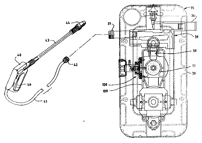
Referring first to Fig. 1, the numeral 35 designates
generally a pressure washer which includes a fluid inlet fitting
36, a fluid outlet fitting 37, and a pump assembly 38 which is
enclosed by an outer case 39. A conventional high pressure
spray gun 40 can be connected to the male threads of the fluid
outlet 37 by a hose 41 having a female coupling 42. The hiqh
pressure gun 40 includes a spray wand 43, an nozzle 44, and a
-5-
2~ 688
spring-biased trigger 46 for opening a valve in the spray gun
When the trigger is not depressed, the spray gun remains
closed
Referring to Figs 2-4, the pump assembly 38 includes a ;
pump housing 48 which is provided with three pump cylinders 49,
and three spring-biased pumping pistons 50 Each of the pistons
is reciprocated by a cam 51, and the cams are rotated by a cam
shaft 52 The cam sha f t 52 is driven by an electric motor 53
having a rotary drive shaft 54 The shafts 52 and 54 are
connected by small and large pulleys 55 and 56 and a drive belt
57
Fig 5 is a sectional view of the pump assembly as
would be seen along the line 5-5 of Fig 4 The pump housing
include~ an lnlet tube 60 tnto which the inlet ~itting 36 is
in--rt-d The inlet tube 60 provides a ~irst inlet passage 61,
and a second inlet passage 62 extends downwardly from the inlet
tub- 60 to a pumping chamber 63 One end of the pump passage 63
i~ clo~ed by a spring-biased inlet check valve 64, and the other
end o~ the pump chamber i9 closed by a spring-biaged outlet
'ch-ck valve 65 An outl-t passage 66 extends from the outlet
ch-ck valv 6S and communicates with the outlet passage of the
outl-t ~itting 37
' . ~ ! . Th- inl-t pa~sage 62 is connected to the inlet openings
o~ the thre- pump chambers 63 by a cross passage 67, and the
outlet openings Or the pump chambers are connected by a cross
pa--ag- 68 ~o th~t the three pumping pistons pUmp in series to
pump rluid rrOm the inl-t to the outl-t
A by-pass passage 71 extends ~rom the outlet passage 66
to the inlet passage 62 and is normally closed by a byopass
valve 72 Referring to Figs 11-13, the by-pass valve ~2 is a
two-stage poppet valve which includes a conically-shaped
small-diameter ~ir t stage 73 and a cylindrical large-diameter
second stage 74 A cylindrical projection 75 extends ~rom the
-6-
- 2~688
second stage 74 and centers a compression spring 76 (Fig 5)
The rear end of the cylindrical projection 75 is provided with a
cruciform groove 7~
Referring to Figs 14 and 15, the by-pass valve 72
seats in a valve seat 80 which is positioned within the by-pass
passage of the pump housing The valve seat includes a
cylindrical inlet portion 81 which is provided with a
longitudinal bore 82 and a cross bore 83 A reduced-diameter
orifice 84 is provided through an annular valve seat 85 An
annular groove 86 is provided on the outer surface of the valve
seat for receiving a sealing gasket 87 (Fig 5)
Referring to Pig 5, the conical end of the by-pass
poppet valve 72 i8 normally maintainod in engagement with the
valv- seat 85 by the spring ~6 Pressurized fluid which is
pumped out Or the pumping chamber 63 flows through the cross
boro 83 o~ the valve seat, through the longitudinal bore 82, and
into the outlot titting 37
Still rererring to Fig 5, the by-pass passage 71
include- a portlon 71a in which the valve 72 is s}idably
po-ition-d, a portlon 71b behind the valve, and a small-diameter
portlon 71c whlch connects with the inlet passage 62 A
switch- wtuating pa-~age 71d connocts passage 71b to a switc~
pa~ag~ 90 which 1~ provided by the inlet tube 60
A rlrst piston or shuttle 91 is slidably positioned in
th- witch pas~age 90 The piston 91 carries a magnetic disc
92 Th- pi~ton can advantageously be rorm-d by in~ection
molding non-rerrou~ mat-rial, ror example D-lrin plastic, around
the magnet A socond piston or shuttle 93 i~ slidably mounted
outside of the pump housing in a cylindrical bore which is
provided within a cylindrical wall 96 on the pump housing ~he
piston 93 also encapsulates a magnet 94 The second magnetic
pi~ton 93 is engageable with a spring-biased push button 97 of a
conventional electrical microswitch 98 Such microswitche~ are
-7-
. 211SB88
well known When the push button is not depressed, the contactsof the switch are open When the push button is depressed, the
contacts are closed The microswitch is connected in series
with a main power switch to provide power to the electric motor
53
Referring to Fig 5, the low pressure fitting 36
includes an outer end 100 and an inner end 101 An internally
threaded female hose coupler 102 is rotatably mounted on the
outer end, and a coil spring 103 is positioned a cylindrical
bore in the inner end A gasket 104 is positioned in an annular
groove and provides a seal with the inlet tube 60
Operation
A source of water or other washing fluid is connected
to th- pr-ssure washer by the inlet fitting 36 Ordinarily, a
garden hoss is connected to the inlet fitting by the hos-
coupler 102 Befor- the water supply is turned on, the ~low
control switch which is provided by th- magnetic pistons 91 and
93 and the electric switch 98 is positioned as illustrat-d in
Fig 5 The magnet~ 92 and 94 hav- common poles facing ach
oth-r, and the int-rnal spring of the spring-actuated push
button 97 rOrc-~ th- piston against the wall 99 of the pu~p
houaing Th- magn-t 92 and piston 91 are magnetically r-p~ d
to th- right away ~rom the magnet 94 The pump housing ls o-d-
of non-ferrous material, for example, BASP Ultraform N2~20
When th- water supply is turned on, the pressur- o~
wat~r which ~low- through the inlot ~itting forces th- pl~ton 91
to th- left as illustrated in Fig 6 The piston 93 is
magnetically repelled to the left and pushes the push but~on
to close the contacts of the switch 98 When the piston 91
moves to the left, the inlet passage 62 is opened, and wa~-r
flows through the cross passage 67 to the inlet chec~ valv-
of each of the pumping chambers 63
When the switch 98 closes, and if the main power 5~ ~t~
is turned on, electric power is supplied to the electric motor
-8-
8 8
53 (Fig 3), and the motor rotates the cam sha~t 52 Thepumping pistons 50 are reciprocated by the rotating cams 51 As
each pumping piston moves away from its its pumping chamber 63,
water is drawn into the pumping cha~ber past the inlet check
valve 64 When the piston moves toward the pumping chamber, the
inlet check valve closes, and water is pumped out of the pumping
chamber past the outlet check valve 65 water which is pumped
from each of the pumping chambers flows through the cross
passage 68, through the valve seat 80, and to the outlet fitting
37 If the valve of the high pressure gun 40 is closed by
depres~ing the trigger 46, high pressure fluid is pumped through
th- pre~surQ gun and is sprayed by the nozzle 44
When the valve in the high pressure gun is held open by
th- trlgger 46, the pressure in the bore 82 of the by-pass val~e
~-at ~0 i~ not ~u~ici-nt to overcome th- force of valve spring
76 to un~eat the ~mall-diameter conical end 73 of the by-pass
valve 72 from the valv- seat 85 However, when the trigger 46
i- r-l-ased and th- valve of the pres~ure gun closes, a high
pr--sure spik o~ rluid pressure hits the conical end 73 of the
~y-pa-- valv- and un~-at~ th- by-pas~ valve from the valve seat
Onc- th- conlcal nd 73 is unseated from the valve seat,
high pr- ur ~luid will contact the large-diameter second stage
74 ~Flg 11) o~ the by-pas~ valve Since the surface area of
th- valve which i~ contacted by fluid when the valve is open is
~ub-tantially gr-at-r than the sur~ac- o~ the conical end or the
valv- whlch i~ contact-d by ~luid when th- valve is closed, the
valv- will b- ~aintained open at a signi~icantly lower pressure
than is required to unseat the valve ~rom the valve seat
When the by-pass valve 72 opens, high pressure fluid
flows past the second stage of the valve through the annular
clearance between the second stage of the valve and the inside
surfase of the by-pass passage 71a The high pressure fluid
flow~ through the by-pass passage 71a and into the passages 71b,
_g_
- 21~688
71c, and 71d The diameter of the portion 71c of the by-pass
passage is significantly less than the diameter of the portions
71b and 71d, and high pressure fluid will contact the left face
of magnetic piston 91 (Fig 6) and force the magnetic piston 91
away from the second magnetic piston 93 The piston 93 is
thereby allowed to be forced against the wall 99 of the housing
by the spring-biased push button of the switch 98, and the
contacts of the switch 98 are opened Power to the electric
motor 53 is thereby turned off, and the pistons 50 stop pumping
Although only a brief period of time elapses between
the time when the high pressure gun is turned off and the time
when electric power to the motor i~ shut off, the pump might
continu- to operate for a short period of time because of
in-rtia Exces~ pres~ure within the pump assembly is relieved
by th- small-diameter by-pas~ pasoage 71c, which allows high
pre~ure ~luid to ~low into the cross passage 67, where it can
be recirculated through the pumping chambers 63 ~;
When th- pres~ure gun 40 is closed and the pump
a~--mbly i~ in th- by-pas~ mode, the pressure of the fluid in
'th- by-p~-- pa~-~g- i~ higher than th- pre~sure o~ the ~luid at
th- inl-t ~lttlng 36 The magnetic piston 91 is thereby
maintaln d ln th po~ition illustrated in Fig 5 in which the
el-ctrlc witch 98 i~ closed and the inlet pa~sagQ 62 is blocked
by the pi~ton 91 The coil sprinq 103 ensure~ that the pressure
within the pu~p a--embly will b- maintain-d higher than the
upply pr--~ur- o~ th- ~luid at the inlet while the high
pr-~ure gun i9 clo~ed Without the coil spring 103, lt would
be much easier to experience a condition in which the pressure
within the pump assembly drops below the supply pressure In
that event, the system becomes unstable, and the flow control
switch would oscillate or hunt for the off condition, i e , the
magnetic piston 91 would oscillate back and forth from an on
position to an of~ position
--10--
211~8
Referring to Fig 11, the angle A of the conical
surface of the first stage 73 of the by-pass valve 74 controls
how fast the by-pass valve opens for a given deflection of the
spring 76 If the angle is too steep, i e , the conical end is
more pointed, not enough flow is able to pass between valve 73
and seat 80 to activate the magnetic piston 91 and the flow
control switch does not function If the angle is too shallow,
i e , the conical end is more blunt, the flow control system
becomes unstable and bounces or hunts for the off condition
The annular space between the large-diameter second
stage 74 of the by-pass valve and the wall of the by-pass
passag- 71a in which the valve reciprocates provides a secondary
orifice of the by-pass valve and controls the flow of fluid past
th- ~econd stage of the valve If the ~pace i9 too small, the
by-pa-s pressure upstream of the valve will be too high, and the
by-pass pressure down-tream of th- valve will be too small to
operat- the flow control switch If the spac- i9 too large, `~
by-pa-s fluid will flow past th- second stage too fast and will
not provid- suf~ici-nt force on th- second stage to maintain the
v~lv- op-n. Th- ratio of the orific- 84 of th- valve seat 85 to
th- dia~ t-r of th- -cond stag- 74 of the by-pass valve is a
ma~or control variabl- in tuning the ~low control switch
In on- p-ci~ic embodim-nt o~ the invention, the angle
A of the conical end of the by-pas- valv- wa- 10 , and the
diam-tor o~ th- orific- through the valv- ~eat 8S wa~ 0 125
inch Th- di~-t-r o~ th- ~econd stag- 74 o~ th- by-pass valve
was 0 49S inch, and th- inside diamet-r of the by-pass passage
71a in which the valve reciprocated was 0 500 inch, leaving a
clearance o~ 0 005 inch
The diameter o~ the small-diameter portion 71c of the
by-pass passage controls the bleed rate of the pump, directs the
high pressure fluid to the left end of the magnet piston 91, and
provides a snap off of the flow control switch when the pressure
--11--
2 ~ 8 8
gun is shut off. If the diameter of the passage 71c is too
large, the flow control switch loses speed of operation. If the
diameter of the passage 71c is too small, the by-pass pressure
goes to unacceptably high pressures.
In one specific embodiment of the by-pass passage, the
diameter of the portion 71b of the passage was 0.150 inch, the
diameter of the portion 71c of the passage was 0.065 inch, and
the diameter of the branch 71d was 0.203 inch. The inside
diameter of the inlet tube 60 which defines the switch passage
90 was 0.625 inch. The outside diameter of the magnet piston 91
was 0.620 inch.
If the fluid supply is turned on while the pressure gun
i~ alo~ed, the pressure of the incoming fluid will initially
mov- tho magnet piston 91 to the left as illustrated in Fig. 6,
clo8e the switch 98, and begin operation of the electric motor
53 and pumping pistons 50. However, the fluid pressure at the
outlet will immediately increase sufficiently to open the
by-pa~ valv- 72, thereby forcing the flow control switch open
to shut o~ pow-r to the motor.
th- ~upply of fluid to the pressure washer is
diocontlnu-d, ~or example, by a kink in the supply hose or by
turning th- ource o~ ~luid off, the fluid pressure which acts
on.th- m~gnot piston 91 will drop sufficiently to permit the
m~gn-t pl~ton 91 to be repelled to the right in Figs. 5 and 6
th-r-by p-rmlttlng the magnet piston 93 to be forced to the
rlght by th- push button 97 and opening the switch 98. Power to
the electric motor i5 thereby shut of~ and the pump is protected
from failure which could be caused by running without fluid.
5Oap Dispenser
The pressure washer is advantageously equipped with a
soap in~ection pump which dispenses soap into the fluid at the
low pressure inlet side of the pump assembly so that the soap
-12-
- 2115~8~
,
~ .
flows through the pump and is forced out of the high pressure
gun at high pressure Heretofore, soap injection in pressure
washers was generally accomplished by using a venturi on the
high pressure side of the pump Operation of the venturi
requires a two-stage nozzle for the high pressure gun A
large-diameter opening for the nozzle is required to create a
high mass flow of water in order to activate the venturi to
aspirate soap into the fluid which flows through the venturi
However, the increased flow of fluid is obtained at the expense
of outlet pressure If the nozzle is operated at a small
diameter in order to provide high pressure washing, the venturi
will not aspirate soap
Referring to Figs 1 and 17, a soap pump assembly 108
1~ bolted to the frame 109 which supports the electric motor,
cam ~haft, and fluid pump as~embly The soap pump assembly
includes a pump body 110 which is supported within a mounting
bracket 111 which i~ bolted to the frame 109 The pump body 110
includes a cylindrical side wall 112 and a pair of radlally
outwardly extending mounting flanges 113 (see also Fig 19)
'Th- pump body ia in--rted into the mounting bracket by pu~ng
th~ ng - 113 pa-t a pair of flexible and resilient r-ta~n~n~
fing-r- 114 on th- mounting flange until the pro~ection~ ar-
po~i~ion-d in a pair of curved undercut grooves 115 (F19~
24-26) in the mounting bracket The pump body i9 then rot-t-d
to lock the pro~ection~ 113 within th- undercut groov-
~
R-r-rrlng to Figs 19-20, th- pump body 110 includ-
~thr-- barbed tub- fittings 117, lla, and 119 The fitting ll7
communicate~ with an inlet passage 120 in the pump body, t~-
fitting 118 communicates with an outlet passage 121, and t~
fitting 119 communicates with a bleed passage 122
Referring to Fig 17, an inlet ball check valv- 121 ~nd
an outlet ball check valve 124 are retained within the inl-t ~nd
outlet passages by a check seat 126 (see also Figs 21-23) ~e
-13-
2 ~ 8 8
check seat 126 includes a cylindrical disk 127 which is providedwith an inlet opening 128, an outlet opening 129, and a bleed
opening 130. The bleed opening 130 extends through a locating
pin 131 which is positioned within the bleed passage 122 of the
pump body. A cylindrical valve seat 132 extends from the check
seat around the outlet opening 129. The inlet ball valve 123 is
biased against a valve seat provided in the pump body by a
spring 133 (Fig. 17), and the outlet ball valve 124 is
resiliently biased against the valve seat 132 by a spring 134.
A soap piston 137 is positioned within a cylindrical
bore 138 of the pump body and is resiliently biased away from
the check seat by a spring 139. The soap piston includes a
rod-shaped projection 140 which extends beyond the mounting
bracket 111 and which engages one of the cams 51 (see Fig. 1)
which reciprocates a pumping piston 50. The soap piston 137 is
thereby reciprocated within the pump body as the cam rotates.
A plastic tube 141 (Fig. 19) is connected to the inlet
fitting 117 and extends into a container of soap, which can be
located outside Or the pressure washer. Ano~her plastic tube
142 can be connected to the bleed fitting 119 and inserted into
the soap container. A third plastic tube 143 is connected to
the outl-t fitting 118 and is connected to a fitting (not shown)
which co~municatea with the inlet passage 62 (Fig. 5) of the
pumR hou~lng. A~ the soap piston 137 reciprocates, soap is
drawn into the bore 138 o~ the pump body through the inlet
~itting 117 and the inlet valve 123 and is pumped out of the
pump body past th- outlet valve 124 and through the outlet
~itting 118.
The bleed opening 122 is provided in the pump body
primarily for priming the pump and for eliminating air bubbles
within the pump. Once the pump is primed and air is eliminated,
very little soap travels through the bleed opening 1~2 and the
bleed fitting 119 because the diameter o~ the bleed openin~ is
substantially smaller than the diameters o~ the inlet and outlet
passages.
-14-
- ` 21~ ~6~8
since the soap is injected into the fluid pump assembly
at the low pressure inlet side, the soap flows through the fluid
pump with the fluid and is pumped through the outlet passage of
the ,luid pump under high pressure, for example, of the order of
1200 to 2000 psi. Soap can therefore be pumped through the high
pressure gun 40 while the nozzle is in the high pressure
setting.
Alternate Embodiment
Figs. 27-30 illustrate an alternate embodiment of a
~low control switch. A switch body 145 is mounted on the pump
housing. The switch body includes a relatively large diameter
inlet passage 146 and an outlet passage 147 which communicates
with the inlet passage 146 through a restricted passage or
ori~ice 148. An L-shaped branch passage 149 connects the outlet
pas~age 147 to the left end of the inlet passage 146.
A piston lS0 is slidably mounted in the left end of the
inlet passage 146 and carries a magnet 151. A magnet 152 is
positioned in a rece~s in the outside of the switch body and
engago~ a pushbutton 153 o~ an electrical microswitch 154. An
annular ~l-ev- 15S i8 secured within the inlet passage 146 to
th- right o~ th- restricted orifice 148 and provides a stop for
th pi~ton lS0. ;~
The inlet fitting 36 which is adaptod to be connected
to th- fluid supply hose is connected to the inlet passage 146,
and th- outlet pa~sage 147 is connected to the inlet passage of
the fluid pump housing. When no fluld ls being supplied by the
fluid source, fluid pressure is equalized within the switch
body, and the passages 146, 147, and 149 are at the same fluid
pressure. The magnet 151 on the piston 150 i~ repulsed by the
magnet 152 and bears against the stop 155 a~ shown in Fig. 29.
The spring-actuated push button 153 of the switch forces the
magnet 152 against the switch body, and the contacts in the
switch are open.
-15-
2115~88
When fluid flows into the inlet passage 146, the
pressure in passage 146 is greater than the pressure in passages
147 and 149, and the piston 150 is forced to the left as
illustrated in Fig 27 The magnet 152 is repulsed and forces
the pushbutton 153 to the left to close the contacts of the
switch and provide power to the electric motor AS the piston
150 moves to the left, the orifice 148 is opened, and fluid is
allowed to flow through the orifice 148 and the outlet passage
147 The restricted orifice 148 provides a pressure
differential between the passages 146 and 147 so that the fluid
pressure in the outlet passage 147 is lower than the fluid
pressure in the inlet passage 146, and the piston 150 is
maintained in the po~ition illustrated in Fig 27 ~;
When fluid flow through the switch body stops, the
pr-~ure~ in the passages 146, 147, and 149 equalize, and the
magnet 151 and the piston 150 are repelled by the magnet 152,
which is forced to the right under the spring force of the push
button 153 80 that the switch contacts open
If de-ir-d, the flow swltch o~ Fig~ 27-30 can be
'provid-d wlth a lld m chanlsm 156 which can maintain the
contact- o~ th- ~icroswitch 154 clo~ed regardless of the flow
condition~ through the switch body 145 When the slide is in
th~ po~ition lllu-trated in Figs 27 and 28, the slide does not
affect op-ration of the flow control switch However, when the
~lid- 1~ moved to th- position illustrated in Figs 29 and 30,
th- ~lld- will retaln the magnet lS2 against th- switch body 145
and pr-v-nt th- magn-t lS2 from moving to th- left to depress
the push button 153 of the microswitch The microswitch will
thereby be retained in an open position regardless of fluid flow
through the ~luid control switch, and the pump will not
operate The end of the switch is bifurcated and engages the
magnet 152 without engaging the push ~utton 153
-16-
".~. . . .
- ` 2115~88
:" While in the foregoing specification a detailed
description of specific embodiments of the invention were set
forth for the purpose of illustration, it wi~l be understood
that many of the details herein given may be varied considerably
by those skilled in the art without departing from the spirit
and scope of the invention.
-17-