Language selection

Search

Patent 2115753 Summary

Third-party information liability

Some of the information on this Web page has been provided by external sources. The Government of Canada is not responsible for the accuracy, reliability or currency of the information supplied by external sources. Users wishing to rely upon this information should consult directly with the source of the information. Content provided by external sources is not subject to official languages, privacy and accessibility requirements.

Claims and Abstract availability

Any discrepancies in the text and image of the Claims and Abstract are due to differing posting times. Text of the Claims and Abstract are posted:

  • At the time the application is open to public inspection;
  • At the time of issue of the patent (grant).
(12) Patent: (11) CA 2115753
(54) English Title: DEVICE FOR INTERNAL CLEANING AND/OR TREATMENT OF LONG CLOSED CHANNELS
(54) French Title: DISPOSITIF POUR LE NETTOYAGE INTERNE OU LE TRAITEMENT DE PROFILE LONGS, FERMES
Status: Deemed expired
Bibliographic Data
(51) International Patent Classification (IPC):
  • B08B 9/04 (2006.01)
(72) Inventors :
  • ERIKSSON, SVEN (Sweden)
(73) Owners :
  • ERIKSSON, SVEN (Sweden)
(71) Applicants :
  • ERIKSSON, SVEN (Sweden)
(74) Agent: GOWLING WLG (CANADA) LLP
(74) Associate agent:
(45) Issued: 2003-04-29
(86) PCT Filing Date: 1992-02-11
(87) Open to Public Inspection: 1993-03-04
Examination requested: 1997-12-17
Availability of licence: N/A
(25) Language of filing: English

Patent Cooperation Treaty (PCT): Yes
(86) PCT Filing Number: PCT/SE1992/000082
(87) International Publication Number: WO1993/003866
(85) National Entry: 1994-02-15

(30) Application Priority Data:
Application No. Country/Territory Date
9102389-5 Sweden 1991-08-19

Abstracts

English Abstract


The invention relates to a device for cleaning and/or treating elongated
closed ducts or channels, particularly ventilation
ducts. The device includes an automotive vehicle (1) and a cleaning and/or
surface treating unit (6) mounted on the vehicle. Also
mounted on the vehicle (1) is a TV-camera (16) or some corresponding device
for monitoring the result of a cleaning and/or treat-
ing operation.


Claims

Note: Claims are shown in the official language in which they were submitted.


6

The embodiments of the invention in which an exclusive
property or privilege is claimed are defined as follows:

1. In a device for internally cleaning elongated
closed ducts and channels, including an automotive vehicle,
a rotary brush mounted thereon, means for rotating the
rotary brush and viewing means mounted on the vehicle for
monitoring the result of a cleaning operation, the
improvement comprising the rotary brush being mounted for
rotation on a shaft which extends generally at right angles
to the longitudinal axis of the ducts.

2. A device according to Claim 1, characterized in
that the rotary brush is mounted on the vehicle by means of
a raisable and lowerable stand structure.

3. A device according to claim 1 or 2, characterized
in that the vehicle is driven electrically and in that the
rotary brush is driven by compressed air.

4. A device according to any one of the preceding
claims, characterized in that the vehicle is a band-driven
vehicle.

5. A device according to claim 4, characterized in
that the vehicle drive bands are guided upwards over guide
rollers at respective ends of the vehicle; and in that the
diameters of the guide rollers are smaller than the
diameters of band-supporting wheels or rollers and are
positioned at a higher level than the band-support wheels
so that the drive bands at respective ends of the vehicle
have an obliquely and upwardly directed run and therewith
enable the vehicle to pass minor obstacles more easily.

Description

Note: Descriptions are shown in the official language in which they were submitted.


dVC~ 93/03~~56 P~fJSE92/000~2
1.
DEVICE FOR INTERNAL CLEANING AND/OR TREATI~EN'f
~F L~NG CLOSEC) CHANNELS
The present invention relates to a device for internal
cleaning andJor treatment of elongated closed channels,
or ducts, preferably ventilation ducts.
It is previously known to clean, for instance, ventila-
tion ducts, or channels, by moving a brush backwards and
forwards~in the ventilation duct, so as to remove dirt
that has adhered to the duct walls. It is also known to
inspect such ducts with the aid of an automotive vehicle
equipped with an inspection camera. The drawback with
these known devices is that they cannot be used simulta-
neously, and consequently it is not possible to inspect
the resx~lt of a cleaning operation until the brush has
been withdrawn from the duct. :Cf the inspection reveals
an unsatisfactory result, it i;a necessary to reinsert
the brush into the duct and carry out a supplementary
clean3.ng operation, this supplementary cleaning opera-
tion being effected by °°guess work°' with the guidance
of
what was revealed by the inspects.~n.
The object of the present invention is therefore to
provide a novel duct cleaning device which will enable
the duct to be inspected during a duct cleaning opera-
tion and a supplementary cleaning operations to be
carried out when so necessary.
3~ The object of the invention .has been realized with a
device hav~.ng the characteristic features set forth in
the following Claims.
The invention will now be described in more detail with
reference to a non-limiting eacemplifying embodiment
thereof illustrated in the accompanying drawings, in


1%'~ 93/038~fi6 P~f/SE92100082
which Fiaure 1 is a schematic perspective view of an
inventive device equipped for the internal cleaning of
ducts of round internal cross-section; Fi~~re 2 is a
schematic perspective view of an inventive device '
equipped for the internal cleaning of ducts having a
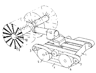
square internal cross-section; and Fiau e~3'is a sche-
i
matic perspective view of an inventive device equipped
for the internal surface treatment of a duct.
The inventive device illustrated in Figure 1 is intended
for cleaning the internal surfaces of ventilation ducts.
The device is primarily intended for cleaning work in
which the internal surfaces of a ventilation duct are
scraped or brushed clean mechanically and in which the
;material thus mechanically removed from the duct walls
is sucked from the duct by means of a suction device, a
vacuum cleaner, connected to an opening in the duct
wall.
The device illustrated in Figure 1 includes an automo~-
tine vehicle 1. The vehicle is preferably driven elec-
trically and is connected to an electric power supply
and which control means located externally of the duct,
via a power and control cable, not shown. The vehicle is
equipped with vehicle drive-bands 2 which pass over
guide rollers 3 at respective ends of the vehicle.-The
diameter of the guide rollers 3 is smaller than the
diameter of wheels or rollers 4 which support the drive
bands 2 and are also positioned on a higher level than
the supporting wheels 4. Thus, the drive bands 2 extend
'' ~obl~.quely' upwards at the ends of the vehicle l, thereby
enabling the vehicle to pass minor obstacles more easi- a
1y. Respective drive bands 2 are driven by means of a
drive wheel 5 mounted in the centre of the vehicle, as
seen in the direction of its longitudinal axis, and
acting directly on respective drive belts 2.


W~ 93/U3866 ~ ~ ~ c~ ~ ~ ~ P'C.°~'/SE92/60082
3
Various ~tyges of cleaning and/or'surface treating units
can be fitted to the vehicle ~., in accordance with
requirements and also in accordance with the configura-
tion and construction of the duct concerned.
The vehicle 1 of the Figure 1 illustration ys fitted
with a cleaning unit in the form of a rotatable brush 6.
The shaft ~ around which the brush ~ rotates extends
generally in the same direction as the longitudinal axis
of the vehicle 1 and, also in the direction of the longi-
tudinal axis of the duct to be cleaned. The brush 6 is
therewith intended for cleaning a duct of internal round
cross-section. The brush G is driven by compressed air,
which can be delivered through a brush connection for
rotation of said brush. The brush 6 is fitted to the
vehacle 3. by means of a stand structure 8. The stand
structure 8 is constructed in .a manner which will enable
the brush shaft 7 to be adjusted t~ different heights in
relation to the vehicle 1, thereby enabling the brush to
be adapted to varying diameters of the ducts to be
cleaned.
Figure 2 illustrates an embodiment of a cleaning unit
intended for cleaning ducts of square internal cross-
section. This unit includes a brush 9 which is rotatable
abe~ut a shaft 10 which extends transversel~r to the duct
axis and thus also transversely in relation to the
vehicle 1. F~.tted in the centre of the transverse shaft
10 is a gear 11 by means of which the shaft is connected
to a drive shaft 12 which extends in the 1~ngitudinal
direction~of the vehicle and which is rotated by com-
pressed air. Similar to the brush 6, the brush 9 may be
mounted on a stand structure which will allow the height
of the brush to be adjusted in relation to the vehicle
1. I~y suitable selection of the size of the brush 9 or
by suitable adjustment to its height in the duct, the


VV~ 93/0386b ~'(:T/SE92/00082
,.~.', ~~ .~~. J r~ J
4
bristles of the brush can be caused to sweep against the
duct walls as the brush rotates and therewith tear lose
dart that has adhered to the duct walls.
As before mentioned, Figure 3 illustrates an inventive
device intended for treating the internal ~su~°facesvof
ducts. The vehicle 1 is fitted with a tubular member 3.3
which extends in the direction of the longitudinal axis
of the vehicle and which is provided at its outermost
end with a spray nozzle 14 by means of which liquid
delivered to the tabular member 13 can be sprayed onto
the duct walls. The tubular member 13 is conveniently
mounted on a stand structure 15 which enables the tubu-
lar member to be adjusted to different heights in rela-
tion to the vehicle 1 and also in relation to the duct
dimensions. The liquid is delivered to the tubular
member 13 by means of a hose knot shown) which is drawn
Tong by the vehicle as it moves in the duct. This
surface treatment may, for ina~tance, involve spraying a
~o cleaning liquid onto the duct walls or spraying paint or
lacquer onto the internal surfaces of the duct walls
subsequent to cleaning the duct.
As shown in Figure 1, in addition to the brush 6, the
vehicle 1 also carries a TV-camera ~.6 which is connected
by means of a cable to the vehicle control means and the
cleaning and/or treating unit. The TV-camera l6 is
suitably pivotal through 180°. The TV-camera enables the
result of a cleaning or surface treatment operation to-
be inspected and monitored directly and, when necessary,
the vehicle can be stopped and moved backwards to a duct
section that has been missed or not cleaned adequately. ,
Although not shown, the units shown in Figures 2 and 3
will also normally include a TV-camera 6. ,

'V~'O 93/0366 ~, ~ ~. ~ r~ ~~ ;~ PC"TAS~92/~00~2
Although not shown in the drawings, in addition to the
TV-camera 16, the vehicle 1 may also be equipped with a
lamp which will enable the result of a cleaning and/or
surface treatment operation to be seen more easily.
5
alternatively, instead of a TV-camera, th~.'_hicle ~~nay
be equipped with some other coauparable device which will
enable the result of a duct cleaning and/or surface
treatment operation to be readily inspected and moni-
toted.

Representative Drawing
A single figure which represents the drawing illustrating the invention.
Administrative Status

For a clearer understanding of the status of the application/patent presented on this page, the site Disclaimer , as well as the definitions for Patent , Administrative Status , Maintenance Fee  and Payment History  should be consulted.

Administrative Status

Title Date
Forecasted Issue Date 2003-04-29
(86) PCT Filing Date 1992-02-11
(87) PCT Publication Date 1993-03-04
(85) National Entry 1994-02-15
Examination Requested 1997-12-17
(45) Issued 2003-04-29
Deemed Expired 2005-02-11

Abandonment History

Abandonment Date Reason Reinstatement Date
2001-02-12 FAILURE TO PAY APPLICATION MAINTENANCE FEE 2001-08-23
2001-05-14 R30(2) - Failure to Respond 2001-10-25

Payment History

Fee Type Anniversary Year Due Date Amount Paid Paid Date
Application Fee $0.00 1994-02-15
Maintenance Fee - Application - New Act 2 1994-02-11 $50.00 1994-02-15
Maintenance Fee - Application - New Act 3 1995-02-13 $50.00 1995-02-06
Maintenance Fee - Application - New Act 4 1996-02-12 $50.00 1996-02-06
Maintenance Fee - Application - New Act 5 1997-02-11 $75.00 1997-02-03
Request for Examination $200.00 1997-12-17
Maintenance Fee - Application - New Act 6 1998-02-11 $75.00 1998-01-26
Maintenance Fee - Application - New Act 7 1999-02-11 $75.00 1999-01-11
Maintenance Fee - Application - New Act 8 2000-02-11 $75.00 2000-02-11
Reinstatement: Failure to Pay Application Maintenance Fees $200.00 2001-08-23
Maintenance Fee - Application - New Act 9 2001-02-12 $75.00 2001-08-23
Reinstatement - failure to respond to examiners report $200.00 2001-10-25
Maintenance Fee - Application - New Act 10 2002-02-11 $200.00 2002-02-11
Final Fee $300.00 2002-11-21
Maintenance Fee - Application - New Act 11 2003-02-11 $200.00 2003-02-10
Owners on Record

Note: Records showing the ownership history in alphabetical order.

Current Owners on Record
ERIKSSON, SVEN
Past Owners on Record
None
Past Owners that do not appear in the "Owners on Record" listing will appear in other documentation within the application.
Documents

To view selected files, please enter reCAPTCHA code :


To view images, click a link in the Document Description column. To download the documents, select one or more checkboxes in the first column and then click the "Download Selected in PDF format (Zip Archive)" or the "Download Selected as Single PDF" button.

List of published and non-published patent-specific documents on the CPD .

If you have any difficulty accessing content, you can call the Client Service Centre at 1-866-997-1936 or send them an e-mail at CIPO Client Service Centre.


Document
Description 
Date
(yyyy-mm-dd) 
Number of pages   Size of Image (KB) 
Cover Page 2003-03-25 1 45
Claims 2001-10-25 1 41
Representative Drawing 2002-05-10 1 16
Cover Page 1995-08-05 1 30
Abstract 1995-08-05 1 70
Claims 1995-08-05 1 43
Drawings 1995-08-05 2 98
Description 1995-08-05 5 281
Claims 1998-08-11 1 38
Representative Drawing 1998-07-21 1 25
Fees 2003-02-10 1 30
Fees 2002-02-11 1 29
Correspondence 2002-11-21 1 41
Prosecution-Amendment 2001-10-25 3 107
Fees 1999-01-11 1 30
Fees 2000-02-11 1 23
Fees 2001-08-23 2 57
Assignment 1994-02-15 5 162
PCT 1994-02-15 10 329
Prosecution-Amendment 1997-12-17 6 214
Prosecution-Amendment 2000-11-14 1 31
Fees 1998-01-26 1 33
Fees 1997-02-03 1 36
Fees 1996-02-06 1 32
Fees 1995-02-06 1 38
Fees 1994-02-15 1 43