Language selection

Search

Patent 2115865 Summary

Third-party information liability

Some of the information on this Web page has been provided by external sources. The Government of Canada is not responsible for the accuracy, reliability or currency of the information supplied by external sources. Users wishing to rely upon this information should consult directly with the source of the information. Content provided by external sources is not subject to official languages, privacy and accessibility requirements.

Claims and Abstract availability

Any discrepancies in the text and image of the Claims and Abstract are due to differing posting times. Text of the Claims and Abstract are posted:

  • At the time the application is open to public inspection;
  • At the time of issue of the patent (grant).
(12) Patent: (11) CA 2115865
(54) English Title: SLIDABLE GRASS CATCHER
(54) French Title: ELEMENT COULISSANT POUR LA RECUPERATION DE L'HERBE
Status: Expired and beyond the Period of Reversal
Bibliographic Data
(51) International Patent Classification (IPC):
  • A01D 43/063 (2006.01)
  • A01D 34/42 (2006.01)
(72) Inventors :
  • REICHEN, RONALD LEE (United States of America)
  • SWENSON, PHILLIP ORLAND (United States of America)
(73) Owners :
  • DEERE & COMPANY
(71) Applicants :
  • DEERE & COMPANY (United States of America)
(74) Agent: BORDEN LADNER GERVAIS LLP
(74) Associate agent:
(45) Issued: 1997-10-07
(22) Filed Date: 1994-02-17
(41) Open to Public Inspection: 1995-02-13
Examination requested: 1994-02-17
Availability of licence: N/A
Dedicated to the Public: N/A
(25) Language of filing: English

Patent Cooperation Treaty (PCT): No

(30) Application Priority Data:
Application No. Country/Territory Date
08/105,548 (United States of America) 1993-08-12

Abstracts

English Abstract


A mechanism for collecting grass clippings cut by a
cutting unit, including a laterally extending member or rail
coupled with the cutting unit, a clippings container or basket
positioned for receiving clippings cut by the cutting unit,
first and second laterally spaced hook members operatively
coupled with the container for engaging the laterally
extending member to operatively couple the container with the
cutting unit, said mechanism allowing an operator standing at
one side of the vehicle to disengage the nearest hook member
from the rail to slide the container toward himself while the
other hook member slides along in engagement with the rail,
thereby facilitating removal.


French Abstract

Mécanisme pour recueillir le gazon coupé par une tondeuse, comprenant un élément ou un rail se déployant latéralement et couplé à la tondeuse, un contenant ou panier à gazon placé de façon à recevoir le gazon coupé par la tondeuse, un premier et un deuxième éléments à crochet espacés latéralement couplés en ordre de fonctionnement au contenant pour s'enclencher avec l'élément qui se déploye latéralement afin de coupler en ordre de fonctionnement le contenant à la tondeuse, ledit mécanisme permettant à un utilisateur se tenant sur un côté du véhicule de dégager l'élément à crochet le plus proche du rail pour faire glisser le contenant vers lui tandis que l'autre élément à crochet glisse de concert en s'engageant dans le rail, facilitant ainsi la dépose.

Claims

Note: Claims are shown in the official language in which they were submitted.

The embodiments of the invention in which an exclusive
property or privilege is claimed are defined as follows:
1. A mechanism for collecting grass clippings, said
mechanism comprising:
a cutting unit for cutting grass and dispersing grass
clippings,
a laterally extending member having a substantially
horizontal middle portion and downwardly extending outer end
portions, said outer end portions being operatively coupled
with the cutting unit,
a pair of stops on said laterally extending member, one
of said stops proximate to each of said outer end portions,
a container positioned on said laterally extending member
for receiving clippings cut by the cutting unit,
first and second laterally spaced engagement members
operatively coupled with the container for engaging the
laterally extending member to operatively couple the container
with the cutting unit, one of said engagement members being
shiftable along substantially the entire lateral length of the
laterally extending member when the other engagement member
has been disengaged from between the stops on the laterally
extending member.
2. The invention of claim 1, wherein said cutting unit
is carried generally beneath a vehicle for allowing an
operator standing at one side of the vehicle to disengage one
of the engagement members from the laterally extending member
for sliding the container toward himself while the other
engagement member slides in engagement on the laterally
extending member such that the operator can then disengage
said other engagement member from the laterally extending
member.
3. The invention of claim 1, wherein the cutting unit is
a reel mower having side frames, the outer end portions of
said laterally extending member being operatively coupled to
respective side frames.
4. The invention of claim 1, wherein said laterally
extending member is operatively coupled to the cutting unit
for supporting the container in a clippings collecting
position in front of the cutting unit.

5. The invention of claim 1, wherein said laterally
extending member is operatively coupled to the cutting unit
for supporting the container in a clippings collecting
position behind the cutting unit.
6. The invention of claim 1, wherein said laterally
extending member is adapted for supporting the container
either in front of or behind the cutting unit for collecting
clippings.
7. The invention of claim 1, wherein said shiftable
engagement member is shiftable to a position whereat the other
engagement member was engaged with the laterally extending
member.
8 A mechanism for collecting grass clippings, said
mechanism comprising:
a cutting unit for mowing grass and discharging grass
clippings,
a laterally extending member having a substantially
horizontal middle portion and downwardly extending outer end
portions, said out end portions being coupled with the cutting
unit,
a pair of stops on said laterally extending member, one
of said stops proximate to each of said outer end portions,
a container positioned on said laterally extending member
for receiving clippings cut by the cutting unit,
first and second laterally spaced hook members
operatively coupled with the container for engaging the
laterally extending member to operatively couple the container
with the cutting unit, one of said hook members being
shiftable along substantially the entire lateral length of the
laterally extending member when the other hook member has been
disengaged from between the stops on the laterally extending
member.
9. The invention of claim 8, wherein said cutting unit
is carried generally beneath a vehicle for allowing an
operator standing at one side of the vehicle to disengage one
of the hook members from the laterally extending member for
sliding the container toward himself while the other hook
member slides in engagement on the laterally extending member

being operatively coupled to and extending between each side
frame.
10. The invention of claim 8, wherein the cutting unit
is a reel mower having side frames, said laterally extending
member being operatively coupled to and extending between each
side frame.
11. The invention of claim 8, wherein said laterally
extending member is operatively coupled to the cutting unit
for supporting the container in clippings collecting position
in front of the cutting unit.
12. The invention of claim 8, wherein said laterally
extending member is operatively coupled to the cutting unit
for supporting the container in clippings collecting position
behind the cutting unit.
13. The invention of claim 8, wherein said laterally
extending member is adapted for supporting the container
either in front of or behind the cutting unit for collecting
clippings.
14. The invention of claim 8, wherein said shiftable
hook member is generally shiftable to a position whereat the
other hook member was engaged with the laterally extending
member.
15. A mechanism for collecting grass clippings, said
mechanism comprising:
a reel mower cutting unit having side frames, said
cutting unit being carried generally beneath a vehicle such
that operator access to the cutting unit is generally limited,
a laterally extending member having a downwardly
extending leg portion operatively coupled with each side frame
of the reel mower cutting unit,
a pair of stops on said laterally extending member, one
of said stops proximate to each said leg portion,
first and second laterally spaced hook members
operatively coupled with a clippings collecting container for
engaging the laterally extending member and operatively
coupling the container with the cutting unit, one of said hook
members being shiftable along substantially the entire lateral
length of the laterally extending member when the other hook

member has been disengaged from between the stops on the
laterally extending member.
16. The invention of claim 15, wherein said mechanism
allows an operator standing at one side of the vehicle to
disengage from the laterally extending member one of the hook
members for sliding the container toward himself while the
other hook member slides in engagement on the laterally
extending member such that the operator can then disengage
said other hook member from the laterally extending member.
17. The invention of claim 15, wherein said laterally
extending member has a generally circular cross-section.
18. The invention of claim 15, wherein said laterally
extending member defines an inverted U-shape, wherein each
said leg portion is operatively coupled to a respective side
frame.
19. The invention of claim 15, wherein said laterally
extending member is operatively coupled to the cutting unit
for supporting the container in clippings collecting position
in front of the cutting unit.
20. The invention of claim 15, wherein said laterally
extending member is operatively coupled to the cutting unit
for supporting the container in clippings collecting position
behind the cutting unit.
21. The invention of claim 15, wherein said laterally
extending member is adapted for supporting the container
either in front of or behind the cutting unit for collecting
clippings.
22. The invention of claim 15, wherein said shiftable
hook member is generally shiftable to a position whereat the
other hook member was engaged with the laterally extending
member.
23. A cutting unit having a direction of travel, a
clippings container and a mechanism for coupling the clippings
container to the cutting unit, said mechanism comprising:
a rail having a substantially horizontal middle portion
and downwardly extending outer end portions, said outer end
portions being operatively coupled with the cutting unit, a
pair of spaced engagement members operatively coupled with the

container and engagable with the rail for coupling the
container with the rail and cutting unit, and
a pair of stops on said laterally extending member, one
of said stops proximate to each of said outer end portions
wherein
said rail extends laterally with respect to the direction
of cutting unit travel, and one of said engagement members is
slidable along substantially the entire lateral length of the
middle portion of the rail when the other of said engagement
members is disengaged from between said stops.
24. The invention of claim 23, wherein the engagement
members are generally hook shaped for engaging the rail.
25. The invention of claim 23 wherein the stops are
coupled with the middle portion of the rail for generally
blocking the engagement members from shifting on the rail
during cutting operations.
26. The invention of claim 23, wherein said slidable
engagement member is slidable to a position whereat the other
engagement member was engaged with the rail.

Description

Note: Descriptions are shown in the official language in which they were submitted.


211586~
SLIDABLE GRASS CATCHER
Background of the Invention:
1. Field of the Invention:
This invention relates to removable grass collection
baskets which are attached to reel mower cutting units for
recelvlng grass clippings, and the mechanisms which couple
such baskets to the cutting unit.
2. Description of the Related Art:
It is known to provide reel mower cutting units with
baskets or containers which are positioned adjacent the
cutting unit to receive grass clippings. When the basket
becomes full of grass clippings the operator will remove or
detach the basket from the cutting unit to empty it at a
desired location.
Various mechanisms have been provided for attaching or
coupling the basket to the cutting unit so that it can be
removed for emptying. One such mechanism provides a pair of
laterally spaced and upwardly projecting rods or stingers
which are fixed to respective left and right sides of the
cutting unit. The basket includes mating openings or slots
into which the stingers are received to hold the basket in
position. The operator removes a full basket by lifting each
side of the basket until the stingers are no longer within the
slots. Some such baskets are coupled to cutting units which
are pushed in front of the vehicle, and allow clearance for
the operator to easily access the basket such that he can
grasp each side of the heavy basket to lift and remove it from
the stingers. However, some cutting units are positioned
beneath the vehicle such that the operator's access to the
basket is limited. When the operator stands beside the
vehicle to remove the full basket from beneath the vehicle he
can relatively easily remove the side of the basket from the
stinger which is on the same side of the cutting unit that he
is standing. But the other side of the basket is difficult to
lift off of its stinger without walking around the vehicle to
the other side, since the operator would have to reach beneath
the vehicle from a relatively low angle to lift the basket
from the stinger. The full basket is relatively heavy, and

2115865
removal of the basket from the stingers can be relatively
difficult due to the awkward way in which the operator must
reach under the vehicle. Other conventional attaching
mechanisms include hooks or brackets located at the sides of
the basket, and therefore they too make it difficult for an
operator to remove a full basket from cutting units positioned
beneath a vehicle.
Furthermore, the position of these cutting units beneath
the vehicle can make it relatively difficult for an operator
to re-attach the basket to the cutting unit once he has
emptied the clippings. As the operator stands at one side of
the vehicle to install the basket beneath the vehicle he can
easily position the side of the basket closest to him onto the
appropriate stinger. However, he may encounter difficulty in
aligning the opening in the other side of the basket with the
stinger on the opposite side of the cutting unit.
Therefore, it would be desirable to provide a clippings
basket and attachment mechanism that allows an operator to
more easily remove a full clippings basket from a reel mower
cutting unit, particularly a cutting unit positioned beneath a
vehicle. It would also be desirable for such a mechanism to
be easily re-attached to the cutting unit beneath the vehicle
once the basket has been emptied.
Summary of the Invention
The preferred embodiment of the present invention
provides a mechanism for attaching a clippings collection
container to a reel mower cutting unit. A laterally extending
tube member or rail is fixed to the cutting unit. The
container includes a pair of laterally spaced hook members
which engage the rail for coupling the container with the
cutting unit. The attachment mechanism can be coupled to
either the front or rear of the cutting units for receiving
grass clippings. The attachment mechanism also allows an
operator to easily install the container on cutting units
positioned beneath a vehicle, and allows him to easily remove
the containers from beneath a vehicle when they become full.

211~855
To install the container beneath a vehicle, the operator
stands beside the vehicle and places one of the hooks on the
rail. He then pushes the container under the vehicle, which
causes the hook to slide along the rail. Once the container
has been pushed under the vehicle the operator can place the
other hook over the rail, thereby fully securing the basket to
the cutting unit. Similarly, when removing a full container,
the operator lifts the hook closest to him off of the rail and
pulls the container toward him, which causes the other hook to
slide along the rail. When the operator can reach the other
hook he lifts it from the rail. The present invention
therefore allows an operator to easily remove and install the
container on a cutting unit beneath the vehicle without
requiring him to reach beneath and across the vehicle in an
awkward manner. Installation and removal are thereby
facilitated.
Brief Description of the Drawings
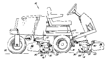
Figure 1 is a side view of a powered vehicle having reel
mower cutting units and the preferred embodiment of the
present attachment mechanism invention.
Figure 2 is a side view of a reel mower cutting unit
which is propelled in front of the vehicle shown in Figure 1,
and having the attachment mechanism according to the preferred
embodiment.
Figure 3 is a side view of a reel mower cutting unit
which is positioned beneath the vehicle shown in Figure 1, and
having the attachment mechanism according to the preferred
embodiment.
Figure 4 is a partially exploded view of the mechanism
which couples the attachment mechanism to the rear of the
cutting unit frame.
Figure 5 is a perspective view of the basket and
attachment mechanism according to the preferred embodiment
which is coupled to the rear of a cutting unit positioned
beneath the vehicle shown in Figure 1.

-- 211~865
Description of the Preferred Embodiment
Referring now to Figure 1, there is shown the preferred
embodiment of the present invention. References to left and
right in the following description will refer to the
operator's left and right when seated on the vehicle 10. The
powered vehicle 10 shown in Figure 1 includes arms 12 with
reel mower cutting units 14 and 16 thereattached. A set of
cutting units 14 are pushed ahead of the vehicle 10, and at
least one cutting unit 16 is positioned beneath the vehicle 10
between the front and rear sets of wheels 18 and 20.
Referring now to Figure 2, there is shown one of the
cutting units 14 which is pushed in front of the vehicle 10.
The cutting units 14 include a frame 22 which supports a
cutting reel (not shown) for rotation about a horizontal and
laterally extending axis. Grass is cut between the rotating
reel blades and a bedknife 26. Front and rear rollers 28 and
30 are coupled to side frames 32 via attachment brackets 34.
The rollers 28 and 30 contact the ground during operation, and
can be adjusted up or down to change the cutting height.
A grass clippings collection system is also provided by
the preferred embodiment. A plastic container or basket 36 is
carried directly in front of and adjacent to the cutting unit
14 for receiving clippings that have been cut by the reel.
The rotation of the reel propels the clippings rearwardly
against a plate 37 which deflects the clippings forwardly into
the basket 36. An attachment mechanism is provided for
releasably coupling the basket 36 to the cutting unit 14. A
pair of U-shaped brackets 38 are bolted or otherwise fixed to
respective sides of the cutting unit 14 between the roller
attachment brackets 34 and the cutting unit side frame 32, as
best seen in Figure 4. End portions of a laterally extending
member or tube 40 are welded to respective U-shaped brackets
38. The middle portion 42 of the rail or tube 40 has a
generally circular cross-section. Stops 44 and 46 are welded
or otherwise fixed to the outer ends of the middle portion 42
of the tube 40. Hooks or engagement members 48 and 50 are
fixed to the basket 36 and are hooked over the tube 40 to

-~ 2~ ~58~ 5
operatively attach the basket 36 to the cutting unit 14 during
mowing operation. The basket 36 can be lifted directly from
the tube 40 when emptying is required, and can be re-installed
by dropping both hooks 48 and 50 directly over the tube 40
simultaneously.
Referring now to Figure 3, there is shown a cutting unit
16 and clippings collection basket 36 which are positioned
beneath the vehicle 10 and between the vehicle wheels 16 and
18 during mowing operation. The clippings basket 36 is
carried at the rear of the cutting unit 16 to receive
clippings which the reel propels to the rear. The plate 37 is
pivoted to its upper position to allow the clippings to pass
by and into the basket 36. The same basket 36 and attachment
mechanism is used in the rear mounted mechanism shown in
Figure 3 as the front mounted mechanism shown in Figure 2.
The U-shaped brackets 38 are coupled to the rear of the side
frames 32, and are bolted or otherwise fixedly positioned
between the side frame 32 and the rear roller support brackets
34. The tube 40 extends upwardly and rearwardly from the U-
shaped brackets 38. The hooks 48 and 50 engage the middle
portion 42 of the tube 40 for coupling the basket 36 with the
cutting unit 16. The weight of the basket 36 and clippings
which accumulate therein urge the basket 36 in a
counterclockwise direction about the tube 40 such that the
basket 36 abuts against the U-shaped brackets 38. Since the
same parts are used in both the front mounted and rear mounted
collection systems the number of parts is reduced, and the
manufacturing costs are correspondingly reduced.
Next, the operation of the cutting units 16 positioned
beneath the vehicle 10 will be discussed. During mowing
operations grass clippings accumulate in the basket 36. When
the basket 36 beneath the vehicle 10 has become full the
operator can walk to the right side of the vehicle 10, and
must reach down to remove the basket 36 which is carried at
the rear of the cutting unit 16. To remove the basket 36, he
grasps the side of the basket 36 nearest him, which is the
right side 52 of the basket 36. He then pivots the basket 36
, . ;

5~ ~
slightly in the clockwise direction, and lifts the right hook
50 off the tube 40. The left hook 48 on the left side 54 of
the basket 36 remains hooked over the tube 40 near the left
stop 44. The operator then can pull the basket 36 toward
himself, sliding the left hook 48 along the rail or tube 40
until it abuts the right stop 46 near the operator. The left
hook 48 is then in a position easily within the operator's
reach such that he can easily lift the left side 54 of the
basket 36 to remove the left hook 48 from the tube 40 while
standing on the right side of the vehicle 10. The preferred
embodiment thereby allows the operator to lift the full basket
36 in two stages from one side of the vehicle 10. He lifts
the side 52 of the basket 36 closest to him to unhook it from
the tube 40, pulls the basket 36 toward him such that the far
hook 48 slides toward him on the tube 40, and then he lifts
the other side 54 of the basket 36 to unhook it from the tube
40. He can therefore apply the lifting forces to the basket
36 at a location he can easily reach from his stance on the
right side of the vehicle 40, without being required to walk
to the other side of the vehicle 10. In this way the operator
can lift the weight of the clippings basket 36 without having
to reach up under the vehicle 10 in a difficult, awkward
manner. The operator has more leverage to lift the heavy
basket 36 such that removal is facilitated.
Once the basket 36 has been emptied, the operator must
re-install the basket 36 on the cutting unit before continuing
mowing operations. To do so, he can stand at the right side
of the vehicle 10 and place the left hook 48 over the middle
portion 42 of the tube 40 just to the left of the right stop
46, which is within easy reach of where he is standing. He
can then push the empty basket 36 under the vehicle 10 such
that the left hook 48 slides or shifts along the tube 40.
When the left hook 48 abuts against the left stop 44 at the
other side of the tube 40 he can position the right hook 50
over the middle portion 42 of the tube 40 just to the left of
the right stop 46. The preferred embodiment thereby allows
the operator to place the far hook 48 over the tube 40 at a
~ ;~

211S~ J
location relatively near where he is standing, and then push
the basket 36 such that the far hook 48 slides to the other
end of the tube 40. The near hook 50 can then also be placed
over the tube 40 near where the operator is standing. The
engagement of the hooks 48 and 50 with the tube 40 is
therefore accomplished at a location near where the operator
is standing such that re-attaching the basket 36 is relatively
easy, and once installed the basket is firmly supported at its
outer ends by the hooks 48 and 50. Unlike the prior art
devices, the preferred embodiment does not require an operator
to reach under the vehicle in an awkward fashion to align the
attachment mechanism. Rather, he can attach each hook 48 and
50 to the tube 40 on the end portion of the tube 40 near where
he is standing. Re-attachment of the basket 36 is therefore
facilitated.
The above description refers to the operator being on the
right side of the vehicle 10 while removing and installing the
clippings basket 36. However, the preferred embodiment also
allows the operator to stand at the left side of the vehicle
10 both for removal of the basket 36 for emptying, and for re-
attaching the basket 36. Operation of the invention from the
left side of the vehicle 10 is performed generally as
described above, with the right hook 50 sliding along the tube
40 during installation and removal instead of the left hook
48. The attachment mechanism described above can also be
utilized on cutting units that are pushed in front of a
vehicle and which are not positioned beneath the vehicle.

Representative Drawing
A single figure which represents the drawing illustrating the invention.
Administrative Status

2024-08-01:As part of the Next Generation Patents (NGP) transition, the Canadian Patents Database (CPD) now contains a more detailed Event History, which replicates the Event Log of our new back-office solution.

Please note that "Inactive:" events refers to events no longer in use in our new back-office solution.

For a clearer understanding of the status of the application/patent presented on this page, the site Disclaimer , as well as the definitions for Patent , Event History , Maintenance Fee  and Payment History  should be consulted.

Event History

Description Date
Inactive: IPC deactivated 2011-07-27
Time Limit for Reversal Expired 2007-02-19
Inactive: First IPC derived 2006-03-11
Inactive: IPC from MCD 2006-03-11
Letter Sent 2006-02-17
Grant by Issuance 1997-10-07
Inactive: Application prosecuted on TS as of Log entry date 1997-07-31
Inactive: Status info is complete as of Log entry date 1997-07-31
Pre-grant 1997-05-29
Notice of Allowance is Issued 1997-01-21
Application Published (Open to Public Inspection) 1995-02-13
All Requirements for Examination Determined Compliant 1994-02-17
Request for Examination Requirements Determined Compliant 1994-02-17

Abandonment History

There is no abandonment history.

Fee History

Fee Type Anniversary Year Due Date Paid Date
Final fee - standard 1997-05-29
MF (patent, 4th anniv.) - standard 1998-02-17 1998-02-16
MF (patent, 5th anniv.) - standard 1999-02-17 1999-02-16
MF (patent, 6th anniv.) - standard 2000-02-17 2000-02-16
MF (patent, 7th anniv.) - standard 2001-02-19 2001-02-16
MF (patent, 8th anniv.) - standard 2002-02-18 2002-02-15
MF (patent, 9th anniv.) - standard 2003-02-17 2003-02-14
MF (patent, 10th anniv.) - standard 2004-02-17 2004-02-03
MF (patent, 11th anniv.) - standard 2005-02-17 2005-02-02
Owners on Record

Note: Records showing the ownership history in alphabetical order.

Current Owners on Record
DEERE & COMPANY
Past Owners on Record
PHILLIP ORLAND SWENSON
RONALD LEE REICHEN
Past Owners that do not appear in the "Owners on Record" listing will appear in other documentation within the application.
Documents

To view selected files, please enter reCAPTCHA code :


To view images, click a link in the Document Description column. To download the documents, select one or more checkboxes in the first column and then click the "Download Selected in PDF format (Zip Archive)" or the "Download Selected as Single PDF" button.

List of published and non-published patent-specific documents on the CPD .

If you have any difficulty accessing content, you can call the Client Service Centre at 1-866-997-1936 or send them an e-mail at CIPO Client Service Centre.


Document
Description 
Date
(yyyy-mm-dd) 
Number of pages   Size of Image (KB) 
Claims 1997-01-20 5 226
Claims 1995-04-13 4 221
Abstract 1995-04-13 1 36
Drawings 1995-04-13 5 286
Description 1995-04-13 7 415
Description 1997-01-20 7 355
Representative drawing 1997-10-01 1 15
Maintenance Fee Notice 2006-04-17 1 172
Fees 1996-02-15 1 40
Fees 1997-02-13 1 72
Fees 1997-02-16 1 62
Fees 1996-02-15 1 40
Prosecution correspondence 1995-11-14 4 158
PCT Correspondence 1997-05-28 1 34