Note: Descriptions are shown in the official language in which they were submitted.
WOg4/~ '2 1 1 ~ ~ 2 ~ PCT/US93/07~
MOTION ~ICTURE DIGITAL 80UND ~b-~M AND NET~OD
WITH p~TM~y SOUND 8TORAGE EDIT CAPABILITY
BACKGROUND OF THE INVENTION
Field of the Invention
This invention relates to systems and methods for pro-
ducing an audio signal in response to a digital time code
on a motion picture film.
Description of the Related Art
Current motion picture films employ analog sound re-
cording techniques. Most motion pictures use an analog
optical sound track that is printed onto the film along
with the picture, and is optically scanned to reproduce the
sound. Another technique is to record the sound onto mag-
netic strips that are coated along the edges of the film;
this process is used for example in producing "Dolby~ 70mm
Sound".
optical sound tracks have a number of shortcomings.
They are suspectable to distortion caused in the laboratory
printing process, have a limited frequency and amplitude
range, and are subject to damage and noise caused by wear
and dirt accumulation. Magnetically recorded sound tracks
are subject to noise problems similar to those encountered
with other audio tapes. It would be highly desirable to
upgrade the quality of motion picture sound to a level com-
parable to that achieved with a compact disk, through the
use of a digital sound system.
Several attempts have been made to achieve a digital
wog4/~ lbD~ PCT/US93/07~
movie sound system. One approach has been to replace the
analog sound track directly with a digital track by record-
ing digital sound data in the area previously occupied by
the analog track on the film. Although theoretically this
approach could be used to yield a higher quality sound re-
production, it has proven difficult for film laboratories
to reliably print the small bit size required to fit the
amount of digital data needed in the restricted area avail-
able. There would also be a fairly low limit to the number
of sound tracks that could be encoded onto the film. As a
practical matter, this type of sound encoding is incompati-
ble with the analog sound reproduction equipment available
in most theaters, and would require the theater to have
special dedicated sound equipment for the digital sound
tracks. Any theater that wanted to run films with this
type of digitally encoded sound track would thus have to
have two separate sets of sound equipment, if they also
wanted to be able to play films with conventional analog
sound tracks. Conversely, the distribution of a film with
such a digital sound track would be likely to suffer be-
cause it could not be run in a theater that had not added
a digital sound capability.
Another approach has been to print the digital infor-
mation in "unused" areas of the motion picture print, such
as between the film's sprocket holes. With this approach
it is also difficult to obtain reliable prints from the
laboratory and to have them remain reliable during extended
use in theaters; the sprocket hole areas of a film are par-
ticularly subject to wear.
An alternate approach is to record the digital sound
data on a separate medium such as a laser disk, and to syn-
chronize the digital sound source with the picture. An
implementation of this approach has been to print a time
code onto the film along with a normal analog sound track,
and to use the time code to directly access the digital
2~ ~6028
sound storage medium. This method does not take into ac-
count the fact that short pieces of film are sometimes re-
moved because of film damage, leaving ~'jumps" or "edits" in
the picture that the sound track must follow. However, an
instantaneous jump in the digital audio is not possible
from most digital audio sources, such as laser disks. Fur-
thermore, maintaining ~ mechanica~ synchronization of a
laser disk to a rilm is difficult.
An attempt has been made to resolve this problem by
transferring the digital audio data from a permanent storage
medium, such as a digital audio tape (DAT) or laser disk, to
an intermediate fast access digital memory, and to then
transfer data from the intermediate memory for conversion to
analog and playback in the theater as needed. This tech-
nique permits virtually instantaneous jumps to be made inthe audio playback to match film edits, and also provides a
simpler synchronization without the need for a constant and
accurate mechanical synchronization of the digital sound
with the picture. However, it has the disadvantage of
limiting the size of edit jumps that can be accommodated to
the size of the intermediate digital buffer memory. Large
jumps require a large memory, which significantly increases
the cost of the system.
SUMMARY OY TI~E INVENTION
The present invention seeks to provide a digital sound
system and method for motion picture films that operates
from a digital time code on the film but requires less mem-
ory than in the related system described above, can accom-
modate edit jumps of virtually unlimited size, can accommo-
date missing time code entries, and eliminates the need to
synchronize the readout from the buffer memory with the
recognition of time code entries read from the film.
These goals a~e achieved by providing a digital time
--A
_~'~. J .
W094/~ ~0 ~1~6~28 PCT/US93/07~
code on the film and storing the movie sound in a digital
audio store, reading the time code from the film as it is
advanced, and accessing the digital audio store to read out
the digital sound data that corresponds to the time code
that has been read. The digital sound data read from the
audio store is loaded into a FIF0 (first in, first out)
digital memory; all of the sound data that is loaded into
the FIF0 memory is later read out from that memory at a
rate that is synchronized to the film speed. The digital
data from the FIF0 memory is then converted to an analog
format for theater playback.
A controller for the digital audio store has an access
time that is less than the film travel time between the
time code reader and the projector's picture projection
aperture, while the digital audio store has a data output
rate capability that is greater than the rate at which the
digital sound data is read out from the FIF0 memory to the
system's digital-to-analog converters (DACs). This allows
jumps in the film to be accommodated by making a corre-
sponding jump within the digital audio store, without in-
terrupting the regular readout of data previously entered
into the FIF0 memory. The FIF0 memory is partially deplet-
ed during the time required to make a jump within the digi-
tal audio store, but is rapidly refilled when the digital
sound signal that corresponds to the new time code has been
accessed within the audio store. Unreadable time code en-
tries can also be easily handled.
The theater motion picture projector is powered from
an alternating current (AC) mains. A readout controller
for the FIF0 memory is preferably synchronized to the AC
main signal, rather than to the time code read from the
film. This allows the system to continue operating despite
absent time code entries, such as those caused by physical
obliteration, and also ensures a positive synchronization
between the film advancement and sound readout rates. The
W094/04g60 ~L~6~8 Pcr/usg3/07666
synchronization between the AC mains and the FIFO memory
controller may be implemented with a phase locked loop,
which also provides a sampling clock signal for the DACs.
The controller for the digital audio store preferably
includes a dynamic random access memory (RAM), within which
the FIFO memory may be implemented. The digital audio
store itself preferably comprises a compact disk read only
memory (CD ROM), although other storage devices may also be
used.
Further features and advantages of the invention will
be apparent to those skilled in the art from the following
detailed description, taken together with the accompanying
drawings.
BRIEF DESCRIPTION OF THE DRAWINGS
FIG. 1 is an enlarged fragmentary view of a motion
picture film segment that includes both a conventional ana-
log sound track, and a digital time code that can be used
for the invention;
FIG. 2 is a simplified fragmentary perspective view
showing a system for reading the digital time code from the
film;
FIG. 3 is a block diagram illustrating a motion pic-
ture digital sound system in accordance with the invention;
FIG. 4 is a block diagram of a phase locked loop that
is preferably used to synchronize both the digital data
readout from the system and the theater projector to an AC
mains;
FIGs. 5a-5d are representations of the FIFO memory
that illustrate its sequential response to a jump in the
digital time code being read;
FIGs. 6a-6f are renderings of the FIFO memory that
illustrate its sequential response to missing time code
entries;
FIG. 7 is a block diagram showing the combination of
wo g4/~ 8 PCT/US93/07~
a DAT and CD as the digital data store; and
FIG. 8 is a block diagram showing the combination of
an analog tape and a CD as the digital data store.
DETAILED DESCRIPTION OF THE INVENTION
The present invention can be used with various digital
time code formats, and there are several possible ways to
place the time code on the film. However, the preferred
time code arrangement involves placing the time code in an
area on the negative between the normal optical sound track
and the picture. This area conventionally serves to iso-
late the optical sound track area from the picture, and is
normally deliberately avoided when reading the sound track
for playback. It lies within the area exposed by the labo-
ratory sound track printing head, but outside the area ex-
posed by the normal laboratory picture printing head. It
is well outside the area scanned by the normal optical
sound playback head on a projector, so that it does not
interfere with the normal optical sound track.
FIG. 1 shows a piece of 35mm release motion picture
film with a digital time code in this area. A series of
sprocket holes 2 lie between the edge 4 of the film and the
normal optical sound track area 6. The picture frames are
printed by a picture printing head in an area 8 that is
spaced inward from the sound track area 6. The intervening
area 10 is used for the digital time code; this area is ex-
posed by the normal laboratory sound track printing head,
but not by the picture printing head. It is usually par-
tially redeveloped by an application process after normal
color processing but before the final fix.
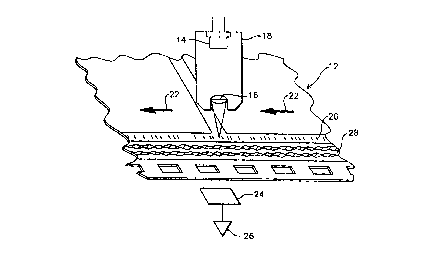
A time code readout system is illustrated in FIG. 2.
The release film print 12 passes under a time code reading
head before advancing to the projector aperture. The read-
ing head illuminates the digital time code area with light
that is absorbed by ~he developed film dyes. A high effi-
W094/~ l lb~8 PCT/US93/07~6
ciency red light emitting diode (LED) 14 is preferably used
for this purpose. The LED 14 is imaged onto the time code
track by a lens 16, preferably as a 0.005"x0.015" spot;
both the LED 14 and the lens 16 are held in a common hous-
ing 18. The digital time code track is indicated by numer-
al 20, with the film moving in the direction of arrows 22.
Light passing through the time code track 20 falls
upon a photocell 24, the output of which is amplified by an
amplifier 26 to provide the digital time code signal used
in audio playback. With the time code positioned on the
film as described above, its reading is unaffected by the
analog sound track 28.
A preferred embodiment of the invention is shown in
FIG. 3. The motion picture film 30 that includes the time
code is advanced from a play out reel 32 past the time code
reading head 18 and the projector 34 to a take up reel 36.
The projector 34 is positioned at a known distance from the
time code reader 18, so that the time required for the film
to travel from the time code reader to the projector with
a normal film advancement speed is precisely known. As de-
scribed below, the present invention provides for an accu-
rate synchronization of the sound playback with the pro-
jected film image, provided the projector remains synchro-
nized to the AC mains.
The time code information from reading head 18 is
transmitted to a data access controller such as the micro-
processor controller 38, which in the preferred embodiment
is an IBM~ PC AT computer that receives the time code data
via an input port. The computer 38 manages all of the sys-
tem's necessary data transfers.
The sound for the movie is stored in a digital audio
store 40. In the preferred embodiment this is a CD ROM
which is driven by a suitable drive such as a Toshiba
XM3300 CD ROM drive, via an SCSI host adapter. Other types
W094/~ PCT/US93/07~
28
of digital data stores could also be used, such as a hard
disk drive, a magneto-optic drive (a laser read/write sys-
tem with a performance similar to a conventional hard disk
drive), or even a relatively slow access device such as a
DAT. The primary requirements for the digital audio store
are (1) its access time must be less than the film travel
time from the time code reading head 18 to the pro~ector
34, thus assuring that a jump can be made to an out-of-se-
quence time code within the audio store before the corre-
sponding portion of the film has reached the projector, and(2) the digital audio store's average data rate capacity
must be greater than the average data rate at which infor-
mation is read out of a FIFO memory (described below) for
delivery to the system's DACs.
The data transfer controller 38 writes the data that
has been read out of audio store 40 into a FIFO memory 42,
which is preferably implemented within the microprocessor's
conventional RAM memory. A small amount of the FIF0 mem-
ory, typically about 2 kilobytes, provides data rate buff-
ering between the PCAT system and the DACs, and is prefer-
ably implemented at least partially on a separate board
that contains the system DACs for convenience in reading
out from the FIFO memory; the cache buffer is symbolically
represented as being below dashed line 34.
A typical application for a FIF0 memory is to receive
input data in bursts, but to read out the data at a con-
stant rate. During periods when no input data is received,
the data already stored in the memory is progressively read
out through its output, with each data byte progressively
dropping down through the successive memory cells (repre-
sented by bars 46). In this manner the memory "empties"
out through its bottom, with the upper memory cells becom-
ing vacant as the readout progresses. The next data burst
"fills" the memory, while data continues to be read out at
the same rate from its bottom. The flow of information
WOg4/~ ~0 PCT/US93/07~
- 2L~6~2g
through the memory from "top" to "bottom" is indicated by
arrows 48.
The minimum capacity size required for the FIF0 memory
42 used in the present invention is equal to the maximum
data access time for the audio store 40; the maximum effec-
tive FIF0 memory capacity for any particular readout rate
is equivalent to the film travel time from the time code
reading head 18 to the aperture of the projector 34. Any
additional FIF0 memory capacity will not be utilized. As
an example, in a typical theater installation that uses two
track digital audio with a one second time of film travel
from the time code reader head 18 to the projection aper-
ture, the FIF0 memory 42 would have to be only 176.4 kilo-
bytes long if a 44.1 kilohertz digital audio sample rate is
used. An even smaller memory can be used if the data
transfer controller 38 can access the digital audio store
40 rapidly enough.
Data is read out from the bottom of the FIF0 memory 42
by a read controller 50 that transfers data out at a con-
stant rate. To operate the system, data transfer control-
ler 38 simply turns on the FIF0 memory read controller 50
via a control line 52 as the first picture frame arrives at
the aperture of projector 34. The theater projector is
powered from an AC mains 52, and the readout of data from
the FIF0 memory 42 is phase locked to the AC mains signal.
This technique eliminates the prior use of the time code
signal for a positive synchronization of the audio playback
to the film projection. Rather, the time code signal is
now used simply to assure that the proper audio data is
supplied to the input of the FIF0 memory 42. By synchro-
nizing the reading out of data from the FIF0 memory to the
AC mains, which also operates the synchronized motor used
in the projector, synchronization between the readout of
the digital audio signal and the projection of the film is
assured.
W094/~ 16~28 PCT/US93/07~6
The digital sound signal read out from the FIF0 memory
42 is transmitted by the read controller 50 to DACs for the
various theater speakers, illustrated as DACs 1-4 for a
four-speaker theater; a single DAC with a multiple output
could also used. The signals are decoded in the usual fas-
hion and amplified by amplifiers Al-A4 for playback in the
theater speakers Sl-S4.
A phase locked loop that is used to synchronize a
readout from the FIFO memory 42, and also the DAC sampling,
with the operation of the projection system is shown in
FIG. 4. The AC mains 54 is illustrated as a power line
with a plug 56 for insertion into a wall socket. The phase
locked loop itself is of conventional design; it may be
implemented for example with an HCT4046A Signetics Inc.
phase locked loop with VCO.
The AC mains signal on line 54 powers the synchronous
motor 58 of the projector, and is also applied to a zero
crossing detector 60 whose output is a 60Hz square wave (in
the United States) that is applied to the signal input of
the phase comparator used in the phase locked loop element
62. The output of the voltage controlled oscillator (VCO)
within the element 62 appears on line 64 and is transmitted
to a frequency divider chain 66, typically implemented as
a counter. The frequency divider output is transmitted
over line 68 to the comparator input of element 62. A
phase comparator output from element 62 is applied over
line 70 to a feedback circuit 72 that control the dynamic
behavior of the phase locked loop. The output of the feed-
back circuit 72 is applied to the VCO control input via
line 74.
The VCO output on line 64 is directed to both the FIF0
memory's read controller 50, and to the sample clock 76 for
DACs 1-4. This output is constant and synchronized with
the AC mains signal, so that the output from the FIFO memo-
ry is obtained at a constant rate without any jumps in the
WOg4/~ PCT/US93/07~6
~ ~ 6~8
FIFO memory.
Locking the operation of the DACs and the FIFO memoryreadout to the AC mains, rather than to the time code read
from the film, allows for a more steady and reliable-sam-
pling clock if one or more of the time code entries are de-
stroyed or unreadable. By using the time code to control
the input of data into the FIFO memory, and the AC mains
signal for continuous synchronization, a much more robust
system is provided; a very stable and reliable output clock
is realized even in the absence of a reliable time code.
The system continually predicts the expected time codes and
simply verifies their presence to assure that the correct
data is being placed from the digital audio store into the
FIFO memory. The present invention can operate even if a
large portion of the time code track is unreadable, since
it requires only periodic confirmation of the predicted
time code entries to proceed, and the clocking of the in-
formation read out from the FIFO memory and the DACs does
not rely upon the time code itself. Rather, the output
clock for both the DACs and the FIFO memory relies upon the
AC mains, which is highly stable and necessarily locked to
the projector. This results in greater simplicity and re-
liability than the prior approaches.
The system's response to a jump in the time code en-
tries read from the film is illustrated in FIGs. 5a-5d.
Assume for example that consecutive time code entries 1, 2,
3 are followed by an abrupt jump to 18, 19, 20, skipping
the intervening entries. This would occur if the portion
of the film corresponding to time codes 4-17 had been dam-
aged and edited out. FIG. 5a illustrates the FIFO memory52 just before the jump occurs. The memory is full, with
data being read in from the "top" and read out from the
"bottom" at the same rate. In FIG. 5b the time code jump
has just been detected, and the microprocessor controller
38 is in the process of making a corresponding jump within
W094/~960 ~66~8 PCT/US93/07~6
the digital audio store 40 to access the address for time
code 18. Until this jump within the audio store has been
completed, data continues to be read out of the FIFO memory
14, while no new data is read in. The FIFO memory thus
begins to "empty", as indicated by arrow 78. In FIG. 5c
the microprocessor controller has completed accessing the
new time code location in the digital audio store and the
FIFO memory begins to rapidly "fill" with data from the
audio store, beginning with the data corresponding to time
code entry 18. Since the data transfer capability from a
base digital store, such as a CD ROM, is greater than the
rate at which data is being removed from the FIFO memory
42, the FIFO memory can refill with data from the audio
store much faster than the data already in the memory is
read out; this rapid input of data is indicated by the mul-
tiple arrows 80. Furthermore, since the maximum random
access time for the base digital store is less than the
film travel time from the time code read head to the pro-
jector's aperture, there is no danger of the FIFO memory
coming close to emptying. The memory is rapidly stabilized
once it has been refilled, as illustrated in FIG. 5d, with
data once again read out at the same rate as it is read in.
The manner in which the system accommodates to one or
more unreadable time codes is illustrated in FIGs. 6a-6f.
Assume that time codes 1 and 2 are initially read, followed
by three illegible time code entries and then time code 6.
FIGs. 6a and 6b illustrate that for time codes 1 and 2 data
is read out from the FIFO memory 42 at the same rate new
data is supplied from the digital audio store. The time
code 1 data enters the uppermost memory cell 42a ln FIG.
6a, and is "pushed" down to the second cell 42b when the
time code 2 data enters cell 42a in FIG. 6b. When the
first illegible time code entry is encountered (FIG. 6c),
the FIFO memory simply continues to read out at the same
uninterrupted rate. Although no time code has been recog-
WOg4/~ ~0 PCT/US93/07~6
nized, the data transfer controller 38 is simply programmed
to read the data for the next time code in sequence (3) out
of the audio store 40 and into the FIFO memory 42. This is
illustrated in FIG. 6c, with the data for time codes 1 and
2 pushed down to the third and second memory cells 42c and
42b, respectively. The same operation is repeated for the
next two unreadable time code entries (FIGs. 6d and 6e),
with the data corresponding to time codes 1-5 occupying the
fifth through first memory cells 42e-42a, respectively,
after the third unreadable entry (FIG. 6e). When the read-
able time code entries resume with time code 6 (FIG. 6f),
the FIFO memory receives the corresponding data from the
audio store without any interruption, and the first six
memory cells 42a-42f are loaded with the data corresponding
to time code entries 6-1 respectively. If the new time
code entry is out of sequence, the data transfer controller
simply jumps to the appropriate data in the audio store and
transfers it to the FIFO memory. The data transfer con-
troller 38 can be programmed to continue transferring se-
quential data from the audio store to the FIFO memory for
any desired number of unreadable time code entries before
entering a fault mode. Until this occurs, data continues
to be written into and read out from the FIFO memory at the
same continuous rate.
While a rapid access digital audio store is preferred,
slower access stores could also be employed. One example
is illustrated in FIG. 7, in which the digital sound infor-
mation is stored in a DAT 84. Assuming the maximum access
time for the DAT is too slow to ensure that jumps can be
made before the FIFO memory 42 empties or the film advances
from the time code reader to the projector aperture, an
intermediate rapid access device such as a hard disk 86
could be provided. Digital audio data is transferred from
the DAT 84 to the disk 86 under the control of the data
transfer controller 38, either in advance of showing the
W094/04960 ~ll 6 ~ PCT/US93/07
14
film or while the film is being projected. Jumps in the
film are then handled within the rapid access disk 86.
This approach could even be extended to an analog audio
store such as a conventional analog magnetic tape 88, il-
lustrated in FIG. 8. Under the control of the datatransfer controller 38 and control line 90, data is read
out from the analog tape, converted to digital form in an
analog-to-digital converter (ADC) 92, and loaded into the
hard disk 86. Again, time code jumps would be handled
within the hard disk.
While the FIFO memory 42 is preferably implemented in
the microprocessor's conventional dynamic RAM, other imple-
mentations are also possible. For example, a conventional
static RAM can be configured into the required FIFO memory
using elements such as the Monolithic Memories Inc. 674219
FIF0 RAM controller.
The present invention has numerous advantages over the
prior approaches described above. It can accommodate jumps
in the film of any length, and its memory requirements are
smaller and less expensive. The need to perform any ad-
dress jumps in the FIFO memory is completely avoided, and
the synchronization of the sound playback to the AC mains
provides for a very robust system. While particular em-
bodiments of the invention have been shown and described,
numerous variations and alternate embodiments will occur to
those skilled in the art. Accordingly, it is intended that
the invention be limited only in terms of the appended
claims.