Language selection

Search

Patent 2116205 Summary

Third-party information liability

Some of the information on this Web page has been provided by external sources. The Government of Canada is not responsible for the accuracy, reliability or currency of the information supplied by external sources. Users wishing to rely upon this information should consult directly with the source of the information. Content provided by external sources is not subject to official languages, privacy and accessibility requirements.

Claims and Abstract availability

Any discrepancies in the text and image of the Claims and Abstract are due to differing posting times. Text of the Claims and Abstract are posted:

  • At the time the application is open to public inspection;
  • At the time of issue of the patent (grant).
(12) Patent: (11) CA 2116205
(54) English Title: CLEANING SYSTEM FOR ELECTROLYTIC TANKS
(54) French Title: SYSTEME DE NETTOYAGE POUR RESERVOIRS D'ELECTROLYTES
Status: Term Expired - Post Grant Beyond Limit
Bibliographic Data
(51) International Patent Classification (IPC):
  • C25C 7/00 (2006.01)
  • C25C 7/06 (2006.01)
(72) Inventors :
  • MENENDEZ, FRANCISCO JAVIER SITGES (Spain)
  • MENENDEZ, FERNANDO SITGES (Spain)
  • TAMARGO, FRANCISCO ALVAREZ (Spain)
  • LEFEVRE, IVES (Spain)
(73) Owners :
  • ASTURIANA DE ZINC, S.A.
(71) Applicants :
  • ASTURIANA DE ZINC, S.A. (Spain)
(74) Agent: MARKS & CLERK
(74) Associate agent:
(45) Issued: 1999-02-23
(22) Filed Date: 1994-02-22
(41) Open to Public Inspection: 1995-02-11
Examination requested: 1996-10-31
Availability of licence: N/A
Dedicated to the Public: N/A
(25) Language of filing: English

Patent Cooperation Treaty (PCT): No

(30) Application Priority Data:
Application No. Country/Territory Date
9301778 (Spain) 1993-08-10

Abstracts

English Abstract


A cleaning system for electrolytic tanks consisting
of a cell with a preferably rectangular layout, very long
relative to its width, and which is provided with at
least one conduit with perforated walls, and preferably
two, which run over the bottom of the cell, along its
length, and ascend alongside the shorter walls until they
reach, approximately, the level of liquid of the tank,
said cell being provided below with surfaces which are
inclined towards the perforated conduits, said conduits
having sufficient cross-sectional area to act as guides
through which are inserted a suction head and pipe for
sludge extraction.


French Abstract

Cette invention concerne un système de nettoyage pour cuves électrolytiques se présentant sous la forme d'une cellule de préférence rectangulaire considérablement plus longue que large, qui comporte au moins un et, de préférence, deux conduits à parois perforées qui sont établies sur le fond dans le sens de la longueur et remontent le long des parois d'extrémité environ jusqu'au niveau du liquide dans ladite cellule qui comporte, sous ce niveau, des surfaces inclinées vers les conduits perforés, lesdits conduits ayant une section transversale suffisante pour qu'on puisse y loger une tête et un tuyau d'aspiration servant à l'extraction des boues.

Claims

Note: Claims are shown in the official language in which they were submitted.

THE EMBODIMENTS OF THE INVENTION IN WHICH AN EXCLUSIVE
PROPERTY OR PRIVILEGE IS CLAIMED ARE DEFINED AS FOLLOWS:
1. An electrolysis installation comprising
(a) a tank for electrolysis including cells, each cell
having a rectangular layout, with a length, a width
shorter than the length, and a depth, a closed
bottom and side walls, and an open top having an
upper edge, each cell being provided along the upper
edge of its longer walls with electrical outlets for
the electrodes as well as insulating supports for
the electrodes, the tank comprising at least one
conduit with perforated walls in each cell, which
conduit runs over the bottom of the cell, along its
length, and ascends alongside the shorter walls to
reach a level for liquid within the tank, the cell
being provided below with surfaces which are
inclined towards at least one perforated conduit,
the conduit having sufficient cross-sectional area
to act as a guide for insertion of a suction head
and pipe for sludge extraction; and
(b) a suction head and pipe for sludge extraction
adapted to be inserted into said conduit.

Description

Note: Descriptions are shown in the official language in which they were submitted.


,._ 1
2l162~~
A CLEANING SYSTEM FOR ELECTROLYTIC TANKS
The present invention relates to a tank for
electrolysis installations, in particular for
installations for the electrolytic production of non-
ferrous metals, such as zinc, copper, etc.
BACKGROUND OF THE INVENTION
Installations for the production of non-ferrous
metals by electrolysis comprise a series of identical
consecutive tanks separated by intermediate walls.
Generally, the tanks have a rectangular layout, very long
compared to the width, said width being determined by the
width of the plates which constitute the cathodes and the
anodes.
During the process of electrolysis, sludges are
produced and deposited progressively partly on the anodes
and partly at the bottom of the tanks and have to be
removed periodically. In order to carry out the

n ~
extraction of these sludges, the process of electrolysis
has to be stopped, with the resulting effect on the
productive process.
Some of the most widely used current procedures for
extracting the sludges consist of using the main bridge
to withdraw some of the anodes and cathodes, thereby
creating an access opening, whilst others consist of
short-circuiting one or a series of tanks and then
removing the sludges, lifting the electrodes or not,
either via the upper part with a suction tube or from
below with a drainage tube at the bottom of the tank.
Then, the operators insert a rigid suction tube and
sweep the bottom of the tank, thereby extracting the
sludges. The electrodes are put back into place.
Another opening is made a little further on and the
process continues.
DESCRIPTION OF THE lNv~NLION
- An object of an aspect of the present invention is a
tank provided with means which enable the sludges to be
removed without having to interrupt the normal operating
process, such that it can be maintained continuously.
According to an aspect of the present invention,
each of the tanks of which the installation consists is
provided with at least one conduit with perforated walls
which runs over the bottom of the cell, along its length,
and ascends alongside the shorter walls until it reaches,
approximately, the level of liquid of said cell or
higher. Preferably, each cell is provided with two
conduits which run over the bottom and ascend alongside
the shorter walls. In any case, the cell is provided
below with surfaces which are inclined towards the tubes
such that the sludges which are produced slide and are
directed towards the perforated conduits.

~ ~ ~ ~ n e
_ 3 ~ ~
The aim of these perforated conduits i~ to act as
guides for inserting a suction head and pipe.
Preferably, the pipe with a suction head is inserted
through the ends of each tube such that the travel of
said head through the tubes is limited to half the length
of the tanks.
With the arrangement described, the sludges which
fall onto the bottom of the tank slide towards the
perforated conduits. When the suction pipe and head are
inserted into a tube the liquid enters via the holes in
the conduits, sweeping along the ~ludges which are
thereby sucked up and extracted to the outside.
As the perforated tubes are installed permanently in
the tanks, the cleaning of said tanks can be carried out
at any time, without having to totally or partially stop
the process of electrolysis.
Another aspect of this invention is as follows:
An electrolysis installation comprising
(a) a tank for electrolysis including cells, each cell
having a rectangular layout, with a length, a width
shorter than the length, and a depth, a closed
bottom and side walls, and an open top having an
upper edge, each cell being provided along the upper
edge of its longer walls with electrical outlets for
the electrodes as well as insulating supports for
the electrodes, the tank comprising at least one
conduit with perforated walls in each cell, which
conduit runs over the bottom of the cell, along its
length, and ascends alongside the shorter walls to
reach a level for liquid within the tank, the cell
being provided below with surfaces which are
inclined towards at least one perforated conduit,
the conduit having sufficient cross-sectional area
to act as a guide for insertion of a suction head
and pipe for sludge extraction; and
.

-
3a
(b) a suction head and pipe for sludge extraction
adapted to be inserted into said conduit.
BRIEF DESCRIPTION OF THE DRAWINGS
The characteristics of the present invention are
described below in greater detail with reference to the
accompanying drawings which show by way of a non-limiting
example one practical embodiment thereof.
In the drawings:
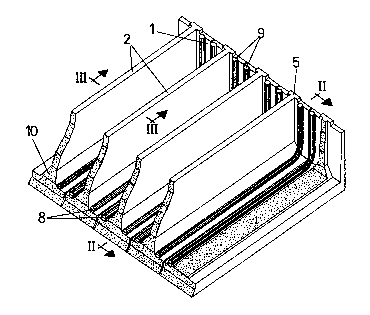
Figure 1 is a partial perspective view of an
electrolysis installation consisting of a series of
consecutive tanks with a rectangular layout and separated
by intermediate walls.
Figure 2 is a partial longitudinal section of a tank
taken along the line II-II of figure 1.
Figure 3 is a cross section of a tank taken along
the line III-III of figure 1.
Figure 4 is a vertical section of one of the
longitudinal walls of the tanks.

211620~
_ 4
DESCRIPTION OF A PREFERRED EMBODIMENT
Figure 1 represents an electrolysis installation
designed for the electrolytic production of non-ferrous
metals consisting of a series of identical consecutive
tanks 1, with a rectangular layout, which are separated
from each other by intermediate longitudinal walls 2. The
tanks are preferably made of concrete, and may be formed
of pre-fabricated modules 3 (figure 3) in the approximate
shape of an inverted T, which constitute the bottom 4 and
longitudinal walls 2 of the tanks, being closed
transversely by means of walls 5 (figures 1 and 2) which
may be continuous across the entire assembly of tanks 1.
The inner surface of the tanks, defined by the
longitudinal walls 2, transverse walls 5 and bottom 4,
are coated with an electrically insulating anti-corrosive
barrier made of a plastic material.
Until now this coating was obtained by applying a
PVC, FRP or lead-based laminar coating to the inner
surfaces of the concrete walls and bottom. During the
cleaning of the tanks, or due to accidental blows
produced during the handling of the electrodes, the
laminar coating was eroded or ripped until it lost its
watertightness.
This problem is avoided by using a special plastic
sheet which is applied to the surface of the formwork
used for concreting the components of the tanks 1. The
plastic sheet used is provided on its free surface with
precise anchorings which are sealed inside the mass of
concrete. When the formwork is removed from the
components, the plastic coating is left fixed to the
pieces of concrete by means of said precise anchorings.
Figure 4 represents a vertical section of the
longitudinal wall which separates consecutive tanks 1 and
shows the coating layer 6, made of a plastic material,

211~2~
_ 5
provided on its inner surface with anchorings 7 which are
fixed to the mass of concrete of the wall 2. The
different joins which may exist in this'layer 6 are made
in such a way that perfect joins and watertightness are
obtained.
As can be seen in figures 1, 2 and 3 two conduits 8
with perforated walls run longitudinally over the bottom
4 of each tank and ascend alongside the tr~nsverse walls
in the form of sections 9 which reach, approximately, the
level of liquid in the tank. The longitudinal walls have
lower sections 10 which are inclined toward$ the conduits
8 with perforated walls. Through the ends of the
ascending sections 9 are inserted a suction head and
pipe, by means of which the sludges are extracted, being
swept along towards the inside of the conduits 8 by the
current of liquid sucked in, through the holes in the
walls.
The purpose of the lower inclined sections 10 of the
tank walls is to convey the sludges which are sedimented
towards the conduits 8. These conduits have perforated
walls, such that as the suction head moves inside them, a
current of liquid is created from the outside to the
inside said conduits and is capable of sweeping the
sludges along.
The arrangement of the perforated guide tubes
enables the work of cleaning the tanks to be carried out
from the lateral walkways, either manually, semi-
automatically or automatically, without interfering with
the other operating sequences of the electrolysis bay.
Furthermore, it enables the sludges to be removed without
the operators having to work over the tanks during said
operation, but rather in a region where the ambient air
quality conforms to the standards in force.
In short, the arrangement of the tubes described
enables the cleaning of the tanks to be carried out

2116205
without having to stop the process and without
interfering with other operations taking place in the
installation, all of which implies an increase in the
deposition yield and a reduction in operating costs.

Representative Drawing
A single figure which represents the drawing illustrating the invention.
Administrative Status

2024-08-01:As part of the Next Generation Patents (NGP) transition, the Canadian Patents Database (CPD) now contains a more detailed Event History, which replicates the Event Log of our new back-office solution.

Please note that "Inactive:" events refers to events no longer in use in our new back-office solution.

For a clearer understanding of the status of the application/patent presented on this page, the site Disclaimer , as well as the definitions for Patent , Event History , Maintenance Fee  and Payment History  should be consulted.

Event History

Description Date
Inactive: Expired (new Act pat) 2014-02-22
Inactive: IPC from MCD 2006-03-11
Grant by Issuance 1999-02-23
Inactive: Correspondence - Formalities 1999-02-09
Inactive: Final fee received 1998-11-09
Pre-grant 1998-11-09
Notice of Allowance is Issued 1998-09-08
Letter Sent 1998-09-08
Inactive: Application prosecuted on TS as of Log entry date 1998-08-31
Inactive: Status info is complete as of Log entry date 1998-08-31
Inactive: IPC assigned 1998-08-11
Inactive: Approved for allowance (AFA) 1998-08-06
All Requirements for Examination Determined Compliant 1996-10-31
Request for Examination Requirements Determined Compliant 1996-10-31
Application Published (Open to Public Inspection) 1995-02-11

Abandonment History

There is no abandonment history.

Maintenance Fee

The last payment was received on 1998-12-23

Note : If the full payment has not been received on or before the date indicated, a further fee may be required which may be one of the following

  • the reinstatement fee;
  • the late payment fee; or
  • additional fee to reverse deemed expiry.

Please refer to the CIPO Patent Fees web page to see all current fee amounts.

Owners on Record

Note: Records showing the ownership history in alphabetical order.

Current Owners on Record
ASTURIANA DE ZINC, S.A.
Past Owners on Record
FERNANDO SITGES MENENDEZ
FRANCISCO ALVAREZ TAMARGO
FRANCISCO JAVIER SITGES MENENDEZ
IVES LEFEVRE
Past Owners that do not appear in the "Owners on Record" listing will appear in other documentation within the application.
Documents

To view selected files, please enter reCAPTCHA code :


To view images, click a link in the Document Description column. To download the documents, select one or more checkboxes in the first column and then click the "Download Selected in PDF format (Zip Archive)" or the "Download Selected as Single PDF" button.

List of published and non-published patent-specific documents on the CPD .

If you have any difficulty accessing content, you can call the Client Service Centre at 1-866-997-1936 or send them an e-mail at CIPO Client Service Centre.


Document
Description 
Date
(yyyy-mm-dd) 
Number of pages   Size of Image (KB) 
Cover Page 1995-05-13 1 60
Abstract 1995-05-13 1 46
Drawings 1995-05-13 2 130
Description 1995-05-13 6 373
Claims 1995-05-13 1 40
Description 1998-06-23 7 220
Claims 1998-06-23 1 29
Cover Page 1999-02-15 1 40
Commissioner's Notice - Application Found Allowable 1998-09-08 1 166
Fees 2003-02-04 1 49
Correspondence 1998-11-09 1 56
Correspondence 1999-02-09 1 35
Fees 2003-12-31 1 51
Fees 2002-01-17 1 49
Fees 1998-12-23 1 54
Fees 2001-01-30 1 51
Fees 1998-01-20 1 57
Fees 2000-01-31 1 51
Fees 2005-01-20 1 54
Fees 2005-12-22 1 50
Fees 2007-01-05 1 50
Fees 2008-01-29 1 58
Fees 2009-01-28 1 58
Fees 2010-02-05 1 63
Fees 2011-02-22 1 64
Fees 2012-02-17 1 63
Fees 1997-01-23 1 61
Fees 1996-01-24 1 48
Prosecution correspondence 1994-02-22 7 284
Prosecution correspondence 1996-10-31 1 24
Prosecution correspondence 1996-10-31 2 47