Language selection

Search

Patent 2116409 Summary

Third-party information liability

Some of the information on this Web page has been provided by external sources. The Government of Canada is not responsible for the accuracy, reliability or currency of the information supplied by external sources. Users wishing to rely upon this information should consult directly with the source of the information. Content provided by external sources is not subject to official languages, privacy and accessibility requirements.

Claims and Abstract availability

Any discrepancies in the text and image of the Claims and Abstract are due to differing posting times. Text of the Claims and Abstract are posted:

  • At the time the application is open to public inspection;
  • At the time of issue of the patent (grant).
(12) Patent Application: (11) CA 2116409
(54) English Title: CLOSURE LID AND CONTAINER
(54) French Title: CONTENANT ET COUVERCLE
Status: Deemed Abandoned and Beyond the Period of Reinstatement - Pending Response to Notice of Disregarded Communication
Bibliographic Data
(51) International Patent Classification (IPC):
  • B65D 17/34 (2006.01)
(72) Inventors :
  • GOULETTE, STEPHEN LEE (United States of America)
  • VADNEY, DAVID JOHN (United States of America)
(73) Owners :
  • STEPHEN LEE GOULETTE
  • DAVID JOHN VADNEY
(71) Applicants :
(74) Agent: GOWLING WLG (CANADA) LLP
(74) Associate agent:
(45) Issued:
(22) Filed Date: 1994-02-24
(41) Open to Public Inspection: 1994-08-27
Availability of licence: N/A
Dedicated to the Public: N/A
(25) Language of filing: English

Patent Cooperation Treaty (PCT): No

(30) Application Priority Data:
Application No. Country/Territory Date
08/023,448 (United States of America) 1993-02-26

Abstracts

English Abstract


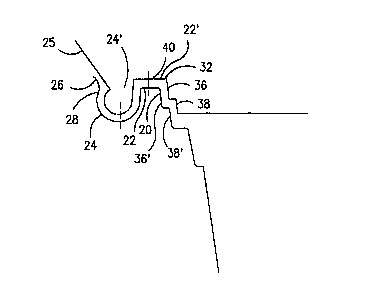
ABSTRACT OF THE DISCLOSURE
The present invention relates to a combination closure lid
and container which includes a container having a bottom, at
least one side wall and a mouth around the top of the wall.
Extending outwardly about the mouth is a flat flange. Extending
just beyond the outer edge of the flange and about the container
is a trough. The top outer wall of the trough joins with an
outwardly protruding lip so as to produce a peripheral undercut
region at the point of joinder. The innermost reach of the
undercut is located at least approximately in the plane of said
flat flange. A lid forms the closure for the mouth of the
container and it conforms to (1) the undercut region, (2) the
trough and (3) the flat flange. The lid has a circumferential
pre-weakened line located in the region of the lid just above
the flat flange when the lid is in place on the container. The
lid also has an integral lift flap located above the flat flange
in communication with the pre-weakened line. The container and
lid is dimensioned so that the lid will close the container by
conformingly engaging the undercut region and the container can
be uncovered by accessing the lift flap, pulling it up to at
least partially sever the lid at said pre-weakened line.


Claims

Note: Claims are shown in the official language in which they were submitted.


- 5 -
WHAT IS CLAIMED IS:
1. In combination a closure lid and a container comprising:
(a) a container having a bottom, at least one side wall and
a mouth around the top of said wall; extending outwardly about
said mouth is a flat flange; extending just beyond the outer
edge of said flange and about said container is a trough, the
top outer wall of said trough joins with an outwardly protruding
lip so as to produce a peripheral undercut region at the
joinder;
(b) a lid forming a closure for the mouth of said
container, the outer periphery of said lid conforming to (1)
said undercut region, (2) said trough and (3) said flat flange;
said lid having a circumferential pre-weakened line located in
the region of the lid just above the flat flange of said
container when the lid is in place on the container; the outer
periphery of said lid including an integral flat pull tab
extending therefrom, the flat flange of said lid also including
a pre-weakened line adjacent to said tab and extending from the
periphery of said lid in a line normal to said circumferential
pre-weakened line; and
(c) said container and lid being dimensioned so that said
lid will close said container by conformingly engaging said
undercut region and said container lid can be freed by pulling
on said tab so as to sever the pre-weakened line thereby
removing the portion of said lid conforming to said (1), (2) and
(3).
2. The container of claim 1 where in both the container mouth
and lid are at least generally circular.
3. The container of claim 1 wherein said pre-weakened line is
a line of perforations.
4. The container of claim 1 wherein the diameter of said
undercut region from one side of said container to the other is
at least approximately the same as that of said lid so that a
close fit between the same is achieved upon closure.

- 6 -
5. The container of claim 1 wherein said lid includes an
integral lift flap as an extension of the periphery of the
severed lid.
6. The container of claim 1 having contacting, conforming step
regions about the lid and just below the mouth of the container.

Description

Note: Descriptions are shown in the official language in which they were submitted.


F-6979-L(SGC)
2 ~
,,,
,'i3A CLOSURE LID AND CONTAINER
FIELD OF THE INVENTION
The present invention pertains to the combination of a
iclosure lid and container, particularly a container which is
~',5 tamper resistant.
BACKG~QUND OF THE INVENTION
There is a continuing need for low-cost, attractive plastic
containers, particularly thermoplastic containers. These
~`containers are of the type that can be used for all types of
~;i10 products, e.g., food, non food solids and semisolids, etc.
It is an object of the present invention to provide a novel
combination of a lid closure and container which permits visual
inspection of the contents and is tamper resistant~
~jSUMMARY OF THE INVENTION
The present invention relates to, in combination, a closure
j lid and a container. The container comprises a bottom having
at least one side wall and mouth around the top of the wall.
Extending outwardly about the mouth is a flat flange. Extending
~l just beyond the outer edge of the flange and about the container
`j20 is a trough. The top outer wall of the trough joins with an
outwardly protruding lip so as to produce a peripheral undercut
region at the joinder of the trough and the lip. For closing
the container there is a lid, the outer periphery of which
-'iconforms to (1) theundercut region, (2) the trough and (3) the
25 flat flange. The lid has a circumferential pre-weakened line
located in the region of the lid just above the flat flange when
the lid is in place on the container. The outer periphery of
the lid also includes an integral pull tab extending therefrom.
The flat flange of the lid includes a pre-weakened line adjacent
30 said tab and extends from the periphery of said lid in a line
normal to said circumferential pre-weakened line. The container
and lid must be dimensioned so that the lid will close the
container by conformingly engaging the undercut region. The
container can be uncovered by pulling the tab so that the pre-
35 weakened lines are severed and the tab and a peripheral strip
s will be separated from the lid;
;~
,~
,. . . I
. ,-. ~ . . .

F-6979-L(SGC)
- 2
:~'
BRIEF DESCRIPTION OF THE DRAWINGS
Figure 1 is a perspective view of the container and lid
combination;
Figure 2 is a partial cross-section of the lid and
5 container mouth taken on the llne 2-2 of Flgure 1; and
igure 3 is a plan view of a part of the lid of the present
invention.
~-i DETAILED DESCRIPTION OF THE INVENTION
The lid and containers of the present invention can be made
lO of any thermoplastic material which can either be injection
molded or thermoformed. In thermoforming the structure,
cooperating male and female dies impose the corresponding
structure in the softened thermoplastic material.
Any thermoplastic material can be employed. A particularly
15 preferred material is amorphous polyethylene terephthalate film
in its transparent form. Other materials include nylon,
I polyolefins, polyvinyl chloride, polystyrene etc. Filler
j pigments can be employed to render the containers opaque.
- Referring to the drawings herein, there is shown a
20 combination 10 of a closure lid and container. The container
12 has a container bottom 16 and at least one container side
wall 18. There is a container mouth 20 near the top of wall 18.
Extending outwardly about the mouth is a flat flange 22 and
extending therefrom, just beyond the outer edge of the flange,
~ 25 is a trough 24. The top outer wall of the trough joins with an
outwardly protruding lip 26 so as to produce a peripheral
undercut region 28 located at least approximately in the plane
of flat flange 22.
The container is closed with a lid 14. The outer periphery
-~ 30 of lid 14 conforms to (1) the undercut region, (2) trough 24 and
' (3) the flat flange 22. This conforming shape 24' of the
-~ periphery of the lid will permit it to be snapped into contact
with this portion of the container. The lid has a
circumferential pre-weakened line 32 located in the region of
35 lid 14 just above flat flange 22 when the lid is in place on the
--, container. The lid also has an integral pull flap 25 located
~ at some point on the periphery of the lid as shown in Figs. l
':i
,~
.. ~: . . : . ' :
: ., .: . .. : . ~ ~
-,. ~ , : : . ~ :

`::
:
A'. ~ F-6979-L(SGC) 2~1~4~
~ -- 3
.'~
and 2. This tab or flap 25 can be any size to accommodate
` pulling with the thumb and forefinger. Adjacent to this tab is
~ another pre-weakened line 27 which extends from the outer edge
; of the lid normal to prs-weakened line 32.
~. .
~ 5 The container and the lid are dimensioned so that the lid
:i ~
will close the container by conformingly engaging the undercut
region 28 and will strongly resist being removed from this
position. During closure, pull tab 25 rotates about 180 to be
~ positioned against the top of the lid. The container is opened
^, 10 by pulling up on pull tab 25 so that the pre-weakened lines 27
1 and 32 are severed and the outer trough 24' and flange 22' are
- removed leaving the lid free to be removed.
~-~ A preferred shape bf the container and lid is that it is
' at least generally circular. Other shapes such as square,
~' 15 triangular, etc. are contemplated. The pre-weakened lines 27
`3 and 32 can be formed by lines of perforations or by a narrowing
; of the thickness dimension of the lid. The length of the
f diameter of the container from one point of the undercut region
' to the other side thereof should be at least approximately the
20 same as that of the diameter of the lid so that a close fit
between the two is achieved upon closure. This will permit the
lid to be snapped in place into the undercut region so securely
that the force needed to pull upward on the integral lift flap
will tear open the pre-weakened lines instead of dislodging the
25 lid at its periphery. A lift tab 40 is located in the periphery
of the freed lid to assist in removal. Both the lid and the
. container have contacting step regions 36, 38, 36' and 38' about
the lid and just below the mouth of the container respectively.
These contacting steps assist, in combination with one another
30 and with other conforming parts, in providing a tightly closed
container. The lid and container combination is more of a
tamper resistant container than it is a tamper evident
container.
~ 35
.~J
,. ~
. -'; .
,~
,,

,J;~ .
F-6979-L(SGC) 21 ~
- 4 -
Although the present invention has been described above by
~` reference to preferred embodiments, it will be appreciated that
: other constructions may be devised, which are, nevertheless,
within the scope and spirit of the inventio:n and are defined by
5 the claims appended hereto.
" ~
, . .
.`:1 10
~.
, .. .
: 15
''!'
.1 .
......
`.. `1 20
?
'.:1
-~1
.-`? 25
' ?
. ;.!
.~ 30
~"~
.-:3
~ 35
.
~- .
.~, . .

Representative Drawing
A single figure which represents the drawing illustrating the invention.
Administrative Status

2024-08-01:As part of the Next Generation Patents (NGP) transition, the Canadian Patents Database (CPD) now contains a more detailed Event History, which replicates the Event Log of our new back-office solution.

Please note that "Inactive:" events refers to events no longer in use in our new back-office solution.

For a clearer understanding of the status of the application/patent presented on this page, the site Disclaimer , as well as the definitions for Patent , Event History , Maintenance Fee  and Payment History  should be consulted.

Event History

Description Date
Time Limit for Reversal Expired 1996-08-24
Application Not Reinstated by Deadline 1996-08-24
Deemed Abandoned - Failure to Respond to Maintenance Fee Notice 1996-02-26
Inactive: Adhoc Request Documented 1996-02-26
Application Published (Open to Public Inspection) 1994-08-27

Abandonment History

Abandonment Date Reason Reinstatement Date
1996-02-26
Owners on Record

Note: Records showing the ownership history in alphabetical order.

Current Owners on Record
STEPHEN LEE GOULETTE
DAVID JOHN VADNEY
Past Owners on Record
None
Past Owners that do not appear in the "Owners on Record" listing will appear in other documentation within the application.
Documents

To view selected files, please enter reCAPTCHA code :


To view images, click a link in the Document Description column. To download the documents, select one or more checkboxes in the first column and then click the "Download Selected in PDF format (Zip Archive)" or the "Download Selected as Single PDF" button.

List of published and non-published patent-specific documents on the CPD .

If you have any difficulty accessing content, you can call the Client Service Centre at 1-866-997-1936 or send them an e-mail at CIPO Client Service Centre.


Document
Description 
Date
(yyyy-mm-dd) 
Number of pages   Size of Image (KB) 
Drawings 1994-08-27 2 83
Cover Page 1994-08-27 1 45
Claims 1994-08-27 2 78
Abstract 1994-08-27 1 46
Descriptions 1994-08-27 4 203
Representative drawing 1998-08-24 1 4