Language selection

Search

Patent 2116699 Summary

Third-party information liability

Some of the information on this Web page has been provided by external sources. The Government of Canada is not responsible for the accuracy, reliability or currency of the information supplied by external sources. Users wishing to rely upon this information should consult directly with the source of the information. Content provided by external sources is not subject to official languages, privacy and accessibility requirements.

Claims and Abstract availability

Any discrepancies in the text and image of the Claims and Abstract are due to differing posting times. Text of the Claims and Abstract are posted:

  • At the time the application is open to public inspection;
  • At the time of issue of the patent (grant).
(12) Patent: (11) CA 2116699
(54) English Title: ELECTRICAL OUTLET FINISHING PLATE
(54) French Title: PLAQUE POUR PRISE DE COURANT
Status: Expired and beyond the Period of Reversal
Bibliographic Data
(51) International Patent Classification (IPC):
  • H02G 03/14 (2006.01)
(72) Inventors :
  • LOGAN, RICHARD (Canada)
(73) Owners :
  • MID-AMERICA BUILDING PRODUCTS CORPORATION
(71) Applicants :
  • MID-AMERICA BUILDING PRODUCTS CORPORATION (United States of America)
(74) Agent:
(74) Associate agent:
(45) Issued: 2002-12-10
(22) Filed Date: 1994-03-01
(41) Open to Public Inspection: 1994-09-13
Examination requested: 1999-02-18
Availability of licence: N/A
Dedicated to the Public: N/A
(25) Language of filing: English

Patent Cooperation Treaty (PCT): No

(30) Application Priority Data:
Application No. Country/Territory Date
08/030,582 (United States of America) 1993-03-12

Abstracts

English Abstract


An electric outlet finishing plate is provided for
use with a wall panel having raised portions and comprises a
one-piece plastic body with front and rear walls. An internal
wall connects the front and rear walls and an external peripheral
wall depends from the front wall. The finishing plate is adapted
to be inserted in an opening which has been cut in the raised
section of the wall panel to provide access to an electrical
outlet while giving a finished appearance thereto.


Claims

Note: Claims are shown in the official language in which they were submitted.

THE EMBODIMENTS OF THE INVENTION IN WHICH AN
EXCLUSIVE PROPERTY OR PRIVILEGE IS CLAIMED ARE DEFINED AS
FOLLOWS:
1. An electrical outlet finishing plate for use
with a wall panel having at least one raised portion
applied to an inside building wall comprising
a one-piece plastic body having a front wall with an
inner periphery and an outer periphery,
an integral rear wall spaced from said front wall
and having a plane,
means on said rear wall to accommodate an electrical
outlet,
indicia on said rear wall such that the rear wall
may be cut along said indicia to provide an opening for the
electrical outlet,
an integral internal wall extending from the inner
periphery of said front wall to said rear wall, and an
integral external peripheral wall extending from the outer
periphery of said front wall toward said rear wall,
said external peripheral wall having a flat external
surface which lies perpendicular to said plane of the rear
wall, and free ends extending to the plane of said rear
wall such that when the finishing plate is used with a wall
panel having raised sections applied to an inside building
-8-

wall with an opening cut from the wall panel through a
raised section for access to an electrical outlet, the body
is inserted within the opening so that said external
peripheral wall abuts the building wall and said front wall
is substantially flush with the raised portion of the wall
panel.
2. The finishing plate set forth in claim 1 wherein
said internal wall is slanted inwardly.
3. The f finishing plate set forth in claim 1 wherein
said body is injection molded.
4. In a method of utilizing a molded plastic wall
panel on an existing inside building wall where the wall
panel has integral raised portions and is applied to the
building wall with a raised portion overlying an electrical
outlet or the like, the method comprising the steps of
cutting and removing a portion of the wall panel
through a raised portion to provide access to an electrical
outlet,
providing a one-piece plastic body having a front
wall with an inner and outer periphery, a rear wall spaced
from the front wall, an internal wall extending from the
inner periphery of the front wall to the rear wall, an
external wall extending from the outer periphery of the
front wall toward the rear wall, and indicia on the rear
-9-

wall such that the rear wall may be cut along the indicia
to provide access to the electrical outlet,
cutting the rear wall along the indicia to conform
to the electrical outlet,
cutting and removing the raised portion adjacent the
electrical outlet to form an opening in the wall panel to
accommodate said plastic body, and
positioning said plastic body in the wall panel at
the opening therein such that a finished appearance is
provided to the wall panel.
5. The method set forth in claim 4 including
providing indicia on said rear wall of said
finishing plate along which said rear wall is cut to form
the opening for the electrical outlet.
-10-

Description

Note: Descriptions are shown in the official language in which they were submitted.


CA 02116699 2002-06-14
This invention relates to a finishing plate for an
electrical outlet. More particularly, this invention
relates to a finishing plate to cover an electrical outlet
located behind a raised portion of wainscotting, paneling
or similar wall panel.
Background of the Invention
In the building industry it may be desirable to
finish inside walls of a building such as, for example, a
house or mobile home, with wainscotting, paneling or
similar building product. Such wall panels may have molded
portions or sections that are raised from the wall to give
the appearance of a raised panel section.
After the wall panel has been applied, it is
generally necessary to cut the wall panel in order to gain
access to an electrical outlet. If the wall panel lies
substantially flat against the wall, a cover plate is
typically attached to the electrical socket by screws
giving a finished appearance. However, if the electrical
outlet appears behind one of the raised sections of the
wall panel, there is a gap or space between the raised
portion and the wall giving a rough and unfinished
appearance.
-1-

It has been proposed in United States Patent Nos.
4,635,168; 4726,152 and 4,920,708 to provide mounting
assemblies to accommodate light fixtures and the like,and to
give a finished appearance to the outside siding of a house.
However, such mounting assemblies are not adapted to give a
finished appearance to an electrical outlet or an inside wall
panel having raised portions or sections.
The present invention provides a finishing plate which
gives a finished appearance to a wall panel that has been cut
to gain access to an electrical outlet; which is attractive;
which is easy to manufacture; which is economical and which is
easy to install.
The device of the present invention is adapted for
use with the inside wall panel of a house or mobile home.
_2_

2~.~~~~9
Summary of the Invention
In accordance with the present invention, an
electrical outlet finishing plate is provided to give a finished
look to a wall panel which has been cut to provide access to
an electrical outlet.
More specifically, the electrical outlet finishing
plate comprises a one-piece plastic body having a front wall,
a substantially planar rear wall spaced from the front wall,
an internal wall connecting the front and rear walls and an
external peripheral wall depending from the front wall such
that when the body is inserted into an opening in the wall
panel, the front wall is substantially flush with the outer
surface of the raised portion of the wall panel.
_3..

~~~.6~~~
Description of the Drawings
FIG. 1 is a front view of the finishing plate in
accordance with the present invention;
FIG. 2 is a sectional view through line 2-2 of FIG. 1;
FIG. 3 is a perspective view of the finishing plate;
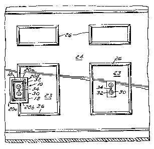
FIG. 4 is a front view of the wall panel with the
finishing plate installed;
FIG. 5 is a partial view of the first step of preparing
the wall panel;
FIG. 6 is a partial view of the next step of preparing
the wall panel;
FIG. 7 is a partial view of the installed finishing
plate with the electrical cover plate; and
FIG. 8 is a sectional view through line 8-8 of FIG. 7.

description
Referring now to FIGS. 1-3, it can be seen that the
finishi~ag plate 10 comprises a one-piece plastic body 12 that
is preferably injection molded having a front wall 14 and a
rear wall 16 that are non-coplanar with each other. The front
wall 14 and rear wall 16 are connected by an inwardly spaced
internal wall 1S. An external peripheral wall shown as outer
walls 20a, 20b, 20c, 20d depend from the front wall 14 extending
substantially perpendicular thereto. The rear wall 16 includes
indicia in the form of a groove 22 that defines a score line
along which the rear wall 16 may be cut and thereby define an
opening for accommodating a standard electrical outlet.
Referring now to FIGS. 4, 5 and 8, it ,can be seen
that the plastic wall panel 24 has a uniform thickness and may
have raised sections 26 giving the appearance of a raised panel
effect. If an electrical outlet 30 is located behind a flat
portion 23 of the wall panel~24, a portion of the panel in the
flat portion 23~is cut and removed to define an opening to gain
access to the electrical outlet 30 and a standard electrical
cover plate 32 is mounted thereto in a typical fashion such as by
a screw 34.
~iowever, if an electrical outlet is located behind
the raised section 26, a portion of the panel must be cut through
the raised section 26 and removed to define an opening for
access to the outlet. Since the raised section 26 is spaced
_g_

from the wall 28, what remains from the opening is a gap or
space between the raised portion 26 and the wall giving a rough
and unfinished appearance.
In accordance with the invention, an opening 25 is
made in the wall panel 24 by cutting through the raised section
26. The size of the opening is sufficient for access to the
electrical outlet 30 (FIB. 5). A portion of the raised section
26 above and below opening 25 is further cut (F'IG. 6) leaving a
gap between the cut ends 27 substantially the size of the height
of the finishing plate 10. The finishing plate 10 is then
inserted therein so that the external peripheral wall, for
example, walls 20a, 20b, abut the cut ends 27 of the raised
section 26. The rear wall 16 and the free ends of the external
peripheral wall such as the outer walls 20a, 20b, 20c, 20d lie
substantially flat against the wall panel 24 and the front wall
14 is substantially flush with the raised section 26 of the
wall panel 24. The finishing plate 10 is preferably molded to
substantially have the configuration of the raised section 2C
so that when in place. the finishing plate 10 blends into the
wall panel 24 giving the appearance that the raised section 26
is continuous and surrounds the electrical outlet 30.'
before inserting the finishing plate 10 into the
opening 25 in the wall panel 24, the rear wall 16 is cut along
the groove 22 to accommodate the electrical outlet 30. After
insertion into the opening 25, a standard electrical cover plate
-6-

~~ibb~~
32 is then mounted on the electrical outlet 30 in a typical
manner as by a screw 34 resulting in a finished appearance of
the wall panel 24.
Thus, the finishing plate of the present invention
provides a finished appearance to the wall panel that has been
cut to provide access to an electrical outlet.
_'_

Representative Drawing
A single figure which represents the drawing illustrating the invention.
Administrative Status

2024-08-01:As part of the Next Generation Patents (NGP) transition, the Canadian Patents Database (CPD) now contains a more detailed Event History, which replicates the Event Log of our new back-office solution.

Please note that "Inactive:" events refers to events no longer in use in our new back-office solution.

For a clearer understanding of the status of the application/patent presented on this page, the site Disclaimer , as well as the definitions for Patent , Event History , Maintenance Fee  and Payment History  should be consulted.

Event History

Description Date
Time Limit for Reversal Expired 2004-03-01
Letter Sent 2003-03-03
Grant by Issuance 2002-12-10
Inactive: Cover page published 2002-12-09
Inactive: Final fee received 2002-09-24
Pre-grant 2002-09-24
Notice of Allowance is Issued 2002-07-31
Letter Sent 2002-07-31
Notice of Allowance is Issued 2002-07-31
Inactive: Approved for allowance (AFA) 2002-07-22
Amendment Received - Voluntary Amendment 2002-06-14
Inactive: S.30(2) Rules - Examiner requisition 2001-12-17
Amendment Received - Voluntary Amendment 1999-04-06
Inactive: Status info is complete as of Log entry date 1999-03-05
Inactive: Application prosecuted on TS as of Log entry date 1999-03-05
Inactive: Adhoc Request Documented 1999-03-05
All Requirements for Examination Determined Compliant 1999-03-05
Letter Sent 1999-03-05
All Requirements for Examination Determined Compliant 1999-02-18
Request for Examination Requirements Determined Compliant 1999-02-18
Application Published (Open to Public Inspection) 1994-09-13

Abandonment History

There is no abandonment history.

Maintenance Fee

The last payment was received on 2002-02-27

Note : If the full payment has not been received on or before the date indicated, a further fee may be required which may be one of the following

  • the reinstatement fee;
  • the late payment fee; or
  • additional fee to reverse deemed expiry.

Patent fees are adjusted on the 1st of January every year. The amounts above are the current amounts if received by December 31 of the current year.
Please refer to the CIPO Patent Fees web page to see all current fee amounts.

Fee History

Fee Type Anniversary Year Due Date Paid Date
MF (application, 4th anniv.) - standard 04 1998-03-02 1998-02-20
Request for examination - standard 1999-02-18
MF (application, 5th anniv.) - standard 05 1999-03-01 1999-02-26
MF (application, 6th anniv.) - standard 06 2000-03-01 2000-02-22
MF (application, 7th anniv.) - standard 07 2001-03-01 2001-02-26
MF (application, 8th anniv.) - standard 08 2002-03-01 2002-02-27
Final fee - standard 2002-09-24
Owners on Record

Note: Records showing the ownership history in alphabetical order.

Current Owners on Record
MID-AMERICA BUILDING PRODUCTS CORPORATION
Past Owners on Record
RICHARD LOGAN
Past Owners that do not appear in the "Owners on Record" listing will appear in other documentation within the application.
Documents

To view selected files, please enter reCAPTCHA code :


To view images, click a link in the Document Description column (Temporarily unavailable). To download the documents, select one or more checkboxes in the first column and then click the "Download Selected in PDF format (Zip Archive)" or the "Download Selected as Single PDF" button.

List of published and non-published patent-specific documents on the CPD .

If you have any difficulty accessing content, you can call the Client Service Centre at 1-866-997-1936 or send them an e-mail at CIPO Client Service Centre.

({010=All Documents, 020=As Filed, 030=As Open to Public Inspection, 040=At Issuance, 050=Examination, 060=Incoming Correspondence, 070=Miscellaneous, 080=Outgoing Correspondence, 090=Payment})


Document
Description 
Date
(yyyy-mm-dd) 
Number of pages   Size of Image (KB) 
Claims 1995-04-07 4 246
Description 1995-04-07 7 403
Claims 2002-06-13 3 81
Description 2002-06-13 7 157
Drawings 1995-04-07 2 67
Abstract 1995-04-07 1 15
Representative drawing 2002-07-22 1 18
Representative drawing 1998-09-02 1 24
Acknowledgement of Request for Examination 1999-03-04 1 178
Commissioner's Notice - Application Found Allowable 2002-07-30 1 164
Maintenance Fee Notice 2003-03-30 1 174
Correspondence 2002-09-23 1 34
Fees 2002-02-26 1 41
Fees 2001-02-25 1 32
Fees 1998-02-19 1 37
Fees 1999-02-25 1 42
Fees 2000-02-21 1 31
Fees 1997-02-20 1 37
Fees 1996-02-22 1 37