Language selection

Search

Patent 2116790 Summary

Third-party information liability

Some of the information on this Web page has been provided by external sources. The Government of Canada is not responsible for the accuracy, reliability or currency of the information supplied by external sources. Users wishing to rely upon this information should consult directly with the source of the information. Content provided by external sources is not subject to official languages, privacy and accessibility requirements.

Claims and Abstract availability

Any discrepancies in the text and image of the Claims and Abstract are due to differing posting times. Text of the Claims and Abstract are posted:

  • At the time the application is open to public inspection;
  • At the time of issue of the patent (grant).
(12) Patent: (11) CA 2116790
(54) English Title: INFEED PLATE FOR AN AXIAL AGRICULTURAL COMBINE
(54) French Title: PLAQUE D'ALIMENTATION D'UNE MOISSONNEUSE-BATTEUSE AXIALE
Status: Term Expired - Post Grant Beyond Limit
Bibliographic Data
(51) International Patent Classification (IPC):
  • A1D 41/12 (2006.01)
  • A1F 12/10 (2006.01)
(72) Inventors :
  • GERBER, MERLE RAY (United States of America)
(73) Owners :
  • DEERE & COMPANY
(71) Applicants :
  • DEERE & COMPANY (United States of America)
(74) Agent: BORDEN LADNER GERVAIS LLP
(74) Associate agent:
(45) Issued: 1999-01-26
(22) Filed Date: 1994-03-02
(41) Open to Public Inspection: 1994-10-01
Examination requested: 1994-03-02
Availability of licence: N/A
Dedicated to the Public: N/A
(25) Language of filing: English

Patent Cooperation Treaty (PCT): No

(30) Application Priority Data:
Application No. Country/Territory Date
08/041,074 (United States of America) 1993-03-31

Abstracts

English Abstract


An improved infeed plate more evenly distributes
harvested crop material as it is transferred from a
feederhouse to an axial rotor. Crop on one side of the infeed
plate is curled into the bottom of the rotor by a conical
section. Crop on the other side of the rotor is introduced to
the top of the rotor by a ramp. Crop in the middle section is
directed to the bottom of the rotor. The ramp section is
provided with an upwardly extending rim.


French Abstract

La présente invention vise un plateau d'alimentation amélioré distribuant de façon plus uniforme les produits de la récolte lors de leur transfert d'une chambre d'alimentation à un rotor axial. Les produits récoltés d'un côté du plateau d'alimentation sont retournés au fond du rotor sous l'action d'une section conique. Les produits récoltés qui sont introduits de l'autre côté du rotor pénètrent au sommet du rotor par une goulotte. Les produits récoltés qui se présentent devant la partie centrale du rotor sont dirigés vers le bas du rotor. La goulotte utilisée est munie d'une jupe à bords relevés.

Claims

Note: Claims are shown in the official language in which they were submitted.

The embodiments of the invention in which an exclusive
property or privilege is claimed are defined as follows:
1. An axial flow agricultural combine comprising:
a supporting structure;
ground engaging means extending from the supporting
structure for transporting the supporting structure across a
field;
an axial rotor housing having a forward open inlet for
receiving harvested crop material, grates through which
threshed and separated grain is removed from the housing, and
a rear open outlet through which non-grain crop material is
removed from the housing;
an axial rotor for threshing and separating a harvested
crop, the rotor being housed in the housing;
a feederhouse through which harvested crop material is
transported to the housing;
a transverse beater being located between the feederhouse
and the housing for directing harvested crop material to the
housing;
an inlet transition section located between the beater
and the inlet of the housing, the inlet transition section
having a transverse upstream section and a transverse
downstream section, the transverse upstream section is
provided with an inclined plate that extends from the beater
to a conical section directing crop to the rotor, the
transverse downstream section having a ramp that is steeper
than the inclined plate of the transverse upstream section,
the ramp is provided with an upwardly extending rim.
2. An axial agricultural combine as defined by claim 1
wherein the ramp is upwardly curved towards the rotor.
3. An axial agricultural combine as defined by claim 2
wherein the transverse downstream section is further provided
with a converging side plate.
4. An axial agricultural combine as defined by claim 3
wherein an oblique ramp is positioned between the side plate
and the ramp.
5. An axial agricultural combine as defined by claim 4
wherein the transverse upstream section is provided with a
converging side plate.

6. An axial flow agricultural combine comprising:
a supporting structure;
ground engaging means extending from the supporting
structure for transporting the supporting structure across a
field;
an axial rotor housing having a forward open inlet for
receiving harvested crop material, grates through which
threshed and separated grain is removed from the housing, and
a rear open outlet through which non-grain crop material is
removed from the housing;
an axial rotor for threshing and separating a harvested
crop, the rotor being housed in the housing;
a feederhouse through which harvested crop material is
transported to the housing;
a transverse beater being located between the feederhouse
and the housing for directing harvested crop material to the
housing;
an inlet transition section located between the beater
and the inlet of the housing, the inlet transition section
having a transverse upstream section and a transverse
downstream section, the transverse upstream section is
provided with an inclined plate that is inclined upwardly to
the rotor from the transverse beater, the transverse
downstream section having a ramp that is steeper than the
inclined plate of the transverse upstream section, the ramp
being provided with an upwardly extending rim.
7. An axial agricultural combine as defined by claim 6
wherein the ramp is upwardly curved towards the rotor.
8. An axial agricultural combine as defined by claim 7
wherein the transverse downstream section is further provided
with a converging side plate.
9. An axial agricultural combine as defined by claim 8
wherein an oblique ramp is positioned between the side plate
and the ramp.
10. An axial agricultural combine as defined by claim 9
wherein the transverse upstream section is provided with a
conical section that is positioned between the inclined plate
and the rotor, the conical section directing crop material to
the rotor.

11. An infeed plate for directing crop material to a
rotor of an axial agricultural combine, the infeed plate
comprising a transverse upstream section having an inclined
plate, and a transverse downstream portion having a ramp that
is steeper than the inclined plate, the ramp is provided with
an upwardly extending rim.
12. An infeed plate as defined by claim 11 wherein the
ramp is curved upwardly.
13. An infeed plate as defined by claim 12 wherein the
transverse downstream section is further provided with a
converging side plate.
14. An infeed plate as defined by claim 13 wherein an
oblique ramp is positioned between the side plate and the
ramp.
15. An infeed plate as defined by claim 14 wherein the
transverse upstream section is provided with a conical section
adjacent to the inclined plate.
16. An infeed plate as defined by claim 15 wherein the
transverse upstream section is provided with a converging side
plate.
17. An infeed plate for directing crop material to a
rotor of an axial agricultural combine, the infeed plate
comprising a transverse upstream section having an inclined
plate and a conical section adjoining the inclined plate, and
a transverse downstream portion having a ramp that is steeper
than the inclined plate, the ramp is provided with a upwardly
extending rim.
18. An infeed plate as defined by claim 17 wherein the
ramp is upwardly curved towards the rotor.
19. An infeed plate as defined by claim 18 wherein the
transverse downstream section is further provided with a
converging side plate.
20. An infeed plate as defined by claim 19 wherein an
oblique ramp is positioned between the side plate and the
ramp.

Description

Note: Descriptions are shown in the official language in which they were submitted.


7 ~
1N~ U PLATE FOR AN AXIAL AGRICULTURAL COMBINE
'
BACKGROUND OF THE lNV~N'l'ION
1. Field of the Invention:
The present invention is directed to an unsymmetrical
infeed plate for directing harvested crop to an axial flow
rotor.
2. Description of the Prior Art:
Agricultural combines are large machines that harvest,
thresh, separate and clean an agricultural crop. The
resulting clean grain is stored in a grain tank located on the
combine. The clean grain can then be transported from the
grain tank to a truck, grain cart or other receiving bin by an
unloading auger.
Axial flow combines have one or two large rotors arranged
along the longitudinal axis of the machine for threshing and
separating the harvested crop material. Harvested crop
material is directed to the axial rotors by a feederhouse.
Most feederhouses transport the harvested crop in a thin mat
ext~n~ing across the width of the feederhouse.
' How the planar movement of this thin mat of crop material
is in~LGd~ced into the axial flow rotor is critical to the
- efficiency of the combine. An unsymmetrical infeed plate was
proposed in U.S. Patent 4,665,929. This proposed inlet
, 25 structure comprises a substantially planar infeed plate
wherein one side of the plate is provided with a steeper ramp.
' In addition, mounting crop dividing guide vanes on the infeed
plate has also been proposed, see U.S. Patent 4,328,815.
SUMM~RY
i 30 It is an object of the present invention to provide an
; Luved unsymmetrical infeed plate which more efficiently
introduces the crop mat into the rotor housing.
It is a feature of the present invention that the
transverse upstream section of the infeed plate is provided
with a conical section and the transverse downstream section
is provided with a curved ramp.
It is another feature of the present invention that the -~
ramp is provided with an upwardly extending rim.
~'' ' ''
; ~.: . . . . .
. .

~1 ~ u73a
Harvested crop from the feederhouse is directed to a
transverse beater which propels the crop material across the
infeed plate to the axial rotor. In the disclosed embodiment
the rotor is rotated counterclockwise when viewed from the
front of the combine. The left side of the infeed plate when
viewed from the front of the combine comprises a transverse
upstream section of the infeed plate, and the right side
comprises a transverse downstream section. If the rotor was
rotated clockwise these sections would be reversed.
As the rotor rotates counterclockwise, harvested crop
material propelled up the transverse upstream section of the
infeed plate is curled towards the rotor and is primarily
directed to the bottom of the rotor by a conical section.
Crop material propelled up the transverse downstream section
is directed up by a steeper curved ramp to the top of the
rotor. The unsymmetrical configuration of the infeed plate
introduces the crop mat to the axial rotor so that it is more
easily rotated by the rotor and taken into the rotor housing.
The ramp is provided with an upwardly ext~n~;n~ rim. The
rim forms a shallow zone in its shadow. Harvested crop
material located in this zone is allowed to slide up a semi~
cylindrical plate to feed the rotor. In addition, the rim
substantially limits the mov -nt of crop material laterally
acro~s the infeed plate. More specifically the
counterclockwise rotation of the rotor tends to drive the crop
material to the transverse downstream section of the infeed
plate. The substantially reduces this tPn~Pncy in the crop
mat. As such the rim provides for a more uniform loading of ~
the rotor. -
The infeed plate forces the crop material into one of
three flow paths. Each flow path introduces the crop mat to
different sections of the rotor, thereby more uniformly
loa~;n~ the rotor. That portion of the crop mat on the
transverse upstream side furthest to the outside is forced
into the conical section and up the adjoining sidewall and is
introduced to the bottom of the rotor. The portion of the
crop mat in the middle of the infeed plate flows up the semi- ;
.: ... . . -

-
cylindrical plate to the side of the rotor. The crop material
furthest to the outside on the transverse downstream section
flows up the ramp and the oblique curved ramp and is
introduced to the top of the rotor. The three streams more
evenly introduce the crop mat to the rotor.
BRIEF DESCRIPTION OF THE DRAWINGS
Figure 1 is a semi-schematic side view of an axial flow -
agricultural combine.
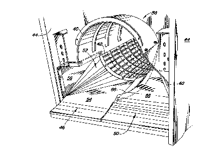
Figure 2 is a perspective view of the infeed plate of the
present invention.
Figure 3 is a top view of the infeed plate.
~; Figure 4 is a front view of the infeed plate.
Figure 5 is an side view taken along line 5--5 in Figure
4.
Figure 6 is a cross sectional view taken along line 6--6
in Figure 4.
D~TP,TT~ DESCRIPTION
Figure 1 shows an agricultural combine 10 comprising a
supporting structure 12 having ground engaging means 14
exten~inq from the supporting structure. A harvesting
, platform 16 is used for harvesting a crop and directing it to
a feederhouse 18. The harvested crop is directed by the
feederhouse 18 to a beater 20. The beater directs the crop
,; upwardly through an inlet transition section 22 to the axial
; 25 crop processing unit 24.
,~ The crop processing unit threshes and ~eparates the
harvested crop material. Grain and chaff fall through grates
on the bottom of the unit 24 to cleaning system 26. The
i cle~ning system 26 L~ ' ves the chaff and directs the clean ~ -
~, 30 grain to a clean grain elevator (not shown). The clean grain elevator deposits the clean grain in grain tank 28. The clean
' grain in the tank can be unloaded into a grain cart or truck
?~,' by unloading auger 30.
p Threshed and separated straw in discharged from the axial
crop processing unit through outlet 32 to discharge beater 34.
The discharge beater in turn propels the straw out the rear of
..
'
.. . . : . : ~ . - . . :: -, . :

illb7~0
.
~ne combine. The operation of the combine is controlled from
operator's cab 36.
The axial crop processing unit comprises a cylindrical
rotor housing 38 and a rotor 39 located inside the housing 38.
The rotor housing has a top portion 40 and a bottom portion
42. The bottom portion is provided with grates through which
grain and chaff fall to the cleaning system. As shown in
Figure 2, the rotor housing and the inlet transition section
are positioned between the sidesheets 44 of the combine. The
sidesheets forming part of the supporting structure of the
combine.
The inlet transition section 22 is best illustrated in
Figures 2-6. The front portion of the rotor projects into the
inlet transition section. This section comprises an infeed
plate having two sections: a transverse upstream section 46
and a transverse downstream section 50. The transverse
upstream section is provided with a conical section 52 which ~ -
starts curling the thin mat of harvested crop material and
~ LGd~ces the crop layer on that side of the infeed plate to
the bottom of the rotor. The beater propelled crop layer on
the transverse upstream side runs along an inclined plate 54
until it contacts the conical section 52. The inclined plate
extends from the transverse beater to the conical section. A
triangular converging side plate 56 and a horizontal ;~
triangular top plate (not shown) further constrain the flow of
the crop material to the rotor. -~
The transverse downstream section is provided with a
~ùLved ramp 58 that curves upwardly towards the rotor. The
~UL ved ramp is steeper than the inclined plate 54.
T ~ tely ~hin~ the ramp is a semi-cylindrical plate 60
which essentially forms part of the rotor housing. The crop
mat is further constrained by oblique curved ramp 62 that~ is
mounted between ramp 58 and planar side plate 64. Crop
material along the outside edge of ramp 58 is thrown up ramp
58 by the beater and engages oblique ramp 62 which throws the
crop material on top of the rotor.
.
~ 4
.

a
The ramp is provided with an upward extending rim 66 that
forms a shallow dead zone behind the ramp. Crop material -
trapped in this zone slides up the semi-cylindrical plate 60
and is transported to the rotor. The rim 66 also keeps crop
material in section 46 from mixing with crop material in
section 50.
In addition to providing this shallow dead zone behind
the ramp, the rim also substantially limits the m~- ?nt of
crop material, propelled by the rotor from moving from the
transverse upstream section to the transverse downstream
section.
The present invention provides a passive system for
efficiently introducing a thin crop mat to an axial crop
processing unit. As such it should not be limited by the - -
above-described embodiment, but should be limited solely by
the claims that follow.
~, ~

Representative Drawing
A single figure which represents the drawing illustrating the invention.
Administrative Status

2024-08-01:As part of the Next Generation Patents (NGP) transition, the Canadian Patents Database (CPD) now contains a more detailed Event History, which replicates the Event Log of our new back-office solution.

Please note that "Inactive:" events refers to events no longer in use in our new back-office solution.

For a clearer understanding of the status of the application/patent presented on this page, the site Disclaimer , as well as the definitions for Patent , Event History , Maintenance Fee  and Payment History  should be consulted.

Event History

Description Date
Inactive: Expired (new Act pat) 2014-03-02
Inactive: IPC from MCD 2006-03-11
Grant by Issuance 1999-01-26
Inactive: Final fee received 1998-09-23
Pre-grant 1998-09-23
Notice of Allowance is Issued 1998-05-04
4 1998-05-04
Letter Sent 1998-05-04
Inactive: Application prosecuted on TS as of Log entry date 1998-04-30
Inactive: Status info is complete as of Log entry date 1998-04-30
Inactive: First IPC assigned 1998-02-12
Inactive: IPC assigned 1998-02-12
Inactive: IPC removed 1998-02-12
Inactive: Approved for allowance (AFA) 1998-02-11
Application Published (Open to Public Inspection) 1994-10-01
Request for Examination Requirements Determined Compliant 1994-03-02
All Requirements for Examination Determined Compliant 1994-03-02

Abandonment History

There is no abandonment history.

Maintenance Fee

The last payment was received on 1998-02-27

Note : If the full payment has not been received on or before the date indicated, a further fee may be required which may be one of the following

  • the reinstatement fee;
  • the late payment fee; or
  • additional fee to reverse deemed expiry.

Patent fees are adjusted on the 1st of January every year. The amounts above are the current amounts if received by December 31 of the current year.
Please refer to the CIPO Patent Fees web page to see all current fee amounts.

Owners on Record

Note: Records showing the ownership history in alphabetical order.

Current Owners on Record
DEERE & COMPANY
Past Owners on Record
MERLE RAY GERBER
Past Owners that do not appear in the "Owners on Record" listing will appear in other documentation within the application.
Documents

To view selected files, please enter reCAPTCHA code :


To view images, click a link in the Document Description column (Temporarily unavailable). To download the documents, select one or more checkboxes in the first column and then click the "Download Selected in PDF format (Zip Archive)" or the "Download Selected as Single PDF" button.

List of published and non-published patent-specific documents on the CPD .

If you have any difficulty accessing content, you can call the Client Service Centre at 1-866-997-1936 or send them an e-mail at CIPO Client Service Centre.

({010=All Documents, 020=As Filed, 030=As Open to Public Inspection, 040=At Issuance, 050=Examination, 060=Incoming Correspondence, 070=Miscellaneous, 080=Outgoing Correspondence, 090=Payment})


Document
Description 
Date
(yyyy-mm-dd) 
Number of pages   Size of Image (KB) 
Claims 1998-01-06 3 155
Drawings 1995-04-13 5 257
Abstract 1995-04-13 1 36
Claims 1995-04-13 3 186
Description 1995-04-13 5 274
Representative drawing 1999-01-18 1 24
Commissioner's Notice - Application Found Allowable 1998-05-03 1 164
Correspondence 1998-09-22 1 39
Fees 1997-02-27 1 63
Fees 1996-02-29 1 53
Examiner Requisition 1996-11-28 2 56
Prosecution correspondence 1997-04-03 4 107