Language selection

Search

Patent 2116795 Summary

Third-party information liability

Some of the information on this Web page has been provided by external sources. The Government of Canada is not responsible for the accuracy, reliability or currency of the information supplied by external sources. Users wishing to rely upon this information should consult directly with the source of the information. Content provided by external sources is not subject to official languages, privacy and accessibility requirements.

Claims and Abstract availability

Any discrepancies in the text and image of the Claims and Abstract are due to differing posting times. Text of the Claims and Abstract are posted:

  • At the time the application is open to public inspection;
  • At the time of issue of the patent (grant).
(12) Patent Application: (11) CA 2116795
(54) English Title: PULL-OUT GUIDE FOR DRAWERS
(54) French Title: GUIDE POUR TIROIRS
Status: Deemed Abandoned and Beyond the Period of Reinstatement - Pending Response to Notice of Disregarded Communication
Bibliographic Data
(51) International Patent Classification (IPC):
(72) Inventors :
  • ROCK, ERICH (Austria)
  • HOLLENSTEIN, HELMUT (Austria)
(73) Owners :
  • JULIUS BLUM GESELLSCHAFT M.B.H.
(71) Applicants :
  • JULIUS BLUM GESELLSCHAFT M.B.H. (Austria)
(74) Agent: MARKS & CLERK
(74) Associate agent:
(45) Issued:
(22) Filed Date: 1994-03-02
(41) Open to Public Inspection: 1994-09-05
Examination requested: 2001-02-01
Availability of licence: N/A
Dedicated to the Public: N/A
(25) Language of filing: English

Patent Cooperation Treaty (PCT): No

(30) Application Priority Data:
Application No. Country/Territory Date
A 412/93 (Austria) 1993-03-04
A 71/94 (Austria) 1994-01-17

Abstracts

English Abstract


A B S T R A C T
A pull-out guide for drawers, having a carcass-side bearing rail
(3) and a drawer-side pull-out rail (6) at each side of the
drawer. Load-transmitting rollers (4, 16, 17) are mounted on the
rails (3, 6). The rails (3, 6) have running webs for the rollers
(4, 16, 17) and the rollers (4, 16, 17) of the bearing rails (3)
and of the pull-out rails (6) are offset perpendicular with
respect to the pull-out direction of the pull-out rails (6) such
that the pull-out rails (6) are guided in two tracks. There are
mounted on the pull-out rails (6) two rollers (16, 17) which are
arranged one above the other and which receive between them the
running web (18) of the bearing rail (3). Next to the upper
roller (16), a support block (12) of plastics is arranged in the
track of the roller (4) mounted on the bearing rail (3).


Claims

Note: Claims are shown in the official language in which they were submitted.

THE EMBODIMENTS OF THE INVENTION IN WHICH AN EXCLUSIVE
PROPERTY OR PRIVILEGE IS CLAIMED ARE DEFINED AS FOLLOWS:
1. Pull-out guide for drawers, having a carcass-side bearing
rail and a drawer-side pull-out rail at each side of the drawer,
load-transmitting, rollers being mounted on the rails and the
rails having running webs for the rollers and the rollers of the
bearing rails and of the pull-out rails being offset
perpendicular with respect to the pull-out direction of the pull-
out rails such that the pull-out rails are guided in two tracks,
characterized in that there are mounted on the pull-out rails (6)
two rollers (16, 17) which are arranged one above the other and
which receive-between them the running web (18) of the bearing
rail (3), in that in parts the bearing rail (3) has an inverted
L-shaped profile, and in that the bearing rail-side roller (4)
is mounted on the side of the vertical web (19) of the bearing
rail (3) opposite the running web (18).
2. Pull-out guide according to Claim 1, characterized in that
bearing rail-side rollers (4) are arranged at each side of the
drawer between the pull-out rail-side rollers (16, 17) and the
carcass side wall.
3. Pull-out guide according to one of Claims 1 to 3,
characterized in that the bearing rails (3) describe, at least
in parts, an assembled Z- and U-shaped profile having two
vertical webs (19, 20) and two horizontal webs, one of which
forms the running web (18), one of the vertical webs (19, 20)
serving as a securing web and one serving as a bearing web for
the bearing rail-side roller (4).
4. Pull-out guide according to one of Claims 1 to 3,
characterized in that a support block (12), preferably of
plastics, is arranged at the rear ends of the pull-out rail (6)
next to the upper roller (16) in the track of the roller (4)
mounted on the bearing rail (3).
5. Pull-out guide according to Claim 4, characterized in that

the support block (12) has a run-on surface (24) for the bearing
rail-side roller (4) and is located at the level of the running
web (22) of the pull-out rail (6) and extends the running web
(22) of the pull-out rail (6) rearwards.
6. Pull-out guide according to Claim 4 or 5, characterized in
that the rollers (16, 17) of the pull-out rail (6) are arranged
behind the running web (22) of the pull-out rail (6).
7. Pull-out guide according to one of Claims 4 to 6,
characterized in that the two rollers (16, 17) of the pull-out
rail (6) are mounted on an adapter (13) secured to the pull-out
rail (6), and in that the support block (12) is supported against
a horizontal web (23) of the adapter (13).
8. Pull-out guide according to Claim 7, characterized in that
the support block (12) is inserted between the horizontal web
(23) of the adapter and the running web (22) of the pull-out rail
(6).
9. Pull-out guide according to Claim 8, characterized in that
the support block (12) has a lug (25) which projects into a hole
(26) in the horizontal web (23) of the adapter (13).
10. Pull-out guide according to one of Claims 4 to 9,
characterized in that the support block (12) is provided on
either side of the run-on surface (24) with guide cheeks (27) for
the bearing rail-side roller (4).
11. Pull-out guide according to one of Claims 1 to 10,
characterized in that both the pull-out rails (6) and the bearing
rails (3) at the running webs (18, 22) have a downwardly open
profile intoowhich a roller (4, 17) projects.

Description

Note: Descriptions are shown in the official language in which they were submitted.


Description
The invention relates to a pull-out guide for drawers, having a
carcass-side bearing rail and a drawer-side pull-out rail at each
side of the drawer, load-transmitting rollers being mounted on
the rails and the rails having running webs for the rollers and
the rollers of the bearing rails and of the pull-out rails being
offset perpendicular with respect to the pull-out direction of
the pull-out rails such that the pull-out rails are guided in two
tracks.
A pull-out guide of this type is described in DE-A1 36 27 408.
It is not suitable for receiving drawers having heavy contents.
The object of the invention is to improve a pull-out guide of
this type such that a good tip-safe guidance of the pull-ou~
rails on the bearing rails is ensured and that the bearing rails
can be constructed to have only one running web.
The object according to the invention is achieved in that there
are mounted on the pull-out rails two rollers which are arranged
one above the other and which receive between them the running
web of the bearing rail, in that in parts the bearing rail has
an inverted L-shaped profile, and in that the bearing rail-side
roller i8 mounted on the side of the vertical web of the bearing
rail opposite the running web.
A preferred embodiment of the inventio~, in which the suspension
of a drawer removed completely from the furniture carcass is
facilitated, provides for a support block, preferably of
plastics, to be arranged at the rear ends of the pull-out rail
next to the upper roller in the track of the roller mounted on
the bearing rail.
An embodiment of the invention will be described in detail below.
Fig. 1 shows, in schematic and exploded manner, a pull-out guide

~ J ~ 3 ~
according to ~he invention having a drawer frame and the drawer
rear wall; Fig. 2 shows a section through a pull-out rail
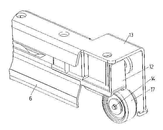
according to the invention, in the rear region; Fig. 3 shows a
diagram of the pull-out rail according to the invention, in the
rear region; Fig. 4 shows a similar diagram to Fig. 3, with
removed run-on block, and ~ig. 5 shows an end view of the pull-
out guide inserted into the drawer frame.
The pull-out guide according to the invention has on each side
of the drawer a bearing rail 3 secured to the furniture carcass
side walls and a pull-out rail 6 connec~ed to the drawer frame
1. The bearing rail 3 has a running web 18 and is provided at
the side of a vertical web 19 opposite the running web 18 with
a roller 4 which i8 mounted on the vertical web 19 by means of
a rivet 5.
The bearing rail 3 is screwed in conventional manner to the
furniture side wall or frame parts of a furniture carcass by way
of a securing web 20. The bearing rail 3 here describes an
assembled Z- and U-shaped profile (Fig. 5~.
The pull-out rail 6 bears at the front end a holding plate 7 on
which a front fitting 8 for securing a front panel can be
screwed. In the drawer frame 1, located in the outer wall 1' in
the region of the front fi~ting 8, is a cutout which enables the
access of a tool to the front fitting 8 and which is covered by
a cover cap 2.
The pull-out rail 6 is further provided with a supporting web 21
for the drawer base and a running web 22 for the bearing rail-
side roller 4.
At the rear end of the pull-out rail 6 an adapter 13 is secured,
for example screwed or riveted, to the pull-out rail 6. The
adapter 13 bears two rollers 16, 17 which are arranged one above
the other and which are mounted on the adapter 13 and thus on the
pull-out rail 6 by means of rivets 14 which project through holes

15 in the adapter 13.
When the drawer is pushed into the furniture carcass, the rollers
16, 17, as can be seén in particular from Fig. 5, àre ~ocated
above and below the running web 18 of the bearing rail 3. The
pull-out rails 6 and the drawer are thus guided in tip-safe
manner on the bearing rails 3.
The adapter 13 has an upper horizontal web 23. Inserted between
the upper horizontal web 23 of the adapter 13 and the running web
22 of the pull-out rail 6 is a support block 12 which projects
rearwards beyond the running web 22 of the pull-out rail 6 and
has a run-on surface 24 which extends the running web 22 beyond
the rollers 16, 17.
The support block 12 has a lug 25 which projects into a hole 26,
for example a punched hole in the horizontal web 23 of the
adapter 13, and holds the support block 12 which is inserted
between the adapter 13 and the horizontal web 22 of the pull-out
rail 6.
The assembly of the rollers 16, 17 on producing the pull-out
guide is facilitated by the fact that the running web 22 of the
pull-out rail 6 terminates hefore the rollers 16, 17. The
support block 12 can easily be inserted between the adapter 13
-and the pull-out rail 6 after the rollers 16, 17 have been
assembled. It facilitates the suspension of the drawer removed
from the furniture carcass and improves the take-up of force by
the pull-out rail 6.
In order to improve the guidance of the bearing rail-side roller
4 in the region of the run-on block 12, the latter is provided
with lateral guide cheeks 27. The guide cheeks 27 e~actly match
the oblique side webs of the downwardly open profile of the
running web $8. The running web 22 of the pull-out rail 6 also
has a downwardly open profile in which the roller 4 is guided.
- .' ~ . ' ' ~! ' `

Also mounted on the adapter 13 is a rear wall holding means 11
for the rear wall 10.
Mounted in the vertical web of the pull-out rail 6 is a block 9,-
preferably of.plastics, which improves the lateral guidance of
the pull-out rail 6. - - -

Representative Drawing
A single figure which represents the drawing illustrating the invention.
Administrative Status

2024-08-01:As part of the Next Generation Patents (NGP) transition, the Canadian Patents Database (CPD) now contains a more detailed Event History, which replicates the Event Log of our new back-office solution.

Please note that "Inactive:" events refers to events no longer in use in our new back-office solution.

For a clearer understanding of the status of the application/patent presented on this page, the site Disclaimer , as well as the definitions for Patent , Event History , Maintenance Fee  and Payment History  should be consulted.

Event History

Description Date
Inactive: IPC expired 2017-01-01
Inactive: IPC from MCD 2006-03-11
Time Limit for Reversal Expired 2003-03-03
Application Not Reinstated by Deadline 2003-03-03
Deemed Abandoned - Failure to Respond to Maintenance Fee Notice 2002-03-04
Letter Sent 2001-03-20
Inactive: Status info is complete as of Log entry date 2001-03-20
Inactive: Application prosecuted on TS as of Log entry date 2001-03-20
Request for Examination Requirements Determined Compliant 2001-02-01
All Requirements for Examination Determined Compliant 2001-02-01
Application Published (Open to Public Inspection) 1994-09-05

Abandonment History

Abandonment Date Reason Reinstatement Date
2002-03-04

Maintenance Fee

The last payment was received on 2001-02-26

Note : If the full payment has not been received on or before the date indicated, a further fee may be required which may be one of the following

  • the reinstatement fee;
  • the late payment fee; or
  • additional fee to reverse deemed expiry.

Patent fees are adjusted on the 1st of January every year. The amounts above are the current amounts if received by December 31 of the current year.
Please refer to the CIPO Patent Fees web page to see all current fee amounts.

Fee History

Fee Type Anniversary Year Due Date Paid Date
MF (application, 4th anniv.) - standard 04 1998-03-02 1998-02-24
MF (application, 5th anniv.) - standard 05 1999-03-02 1999-02-25
MF (application, 6th anniv.) - standard 06 2000-03-02 2000-02-25
Request for examination - standard 2001-02-01
MF (application, 7th anniv.) - standard 07 2001-03-02 2001-02-26
Owners on Record

Note: Records showing the ownership history in alphabetical order.

Current Owners on Record
JULIUS BLUM GESELLSCHAFT M.B.H.
Past Owners on Record
ERICH ROCK
HELMUT HOLLENSTEIN
Past Owners that do not appear in the "Owners on Record" listing will appear in other documentation within the application.
Documents

To view selected files, please enter reCAPTCHA code :


To view images, click a link in the Document Description column. To download the documents, select one or more checkboxes in the first column and then click the "Download Selected in PDF format (Zip Archive)" or the "Download Selected as Single PDF" button.

List of published and non-published patent-specific documents on the CPD .

If you have any difficulty accessing content, you can call the Client Service Centre at 1-866-997-1936 or send them an e-mail at CIPO Client Service Centre.


Document
Description 
Date
(yyyy-mm-dd) 
Number of pages   Size of Image (KB) 
Representative drawing 1998-08-11 1 21
Abstract 1995-06-09 1 30
Claims 1995-06-09 2 89
Drawings 1995-06-09 5 210
Description 1995-06-09 4 192
Reminder - Request for Examination 2000-11-05 1 119
Acknowledgement of Request for Examination 2001-03-19 1 179
Courtesy - Abandonment Letter (Maintenance Fee) 2002-04-01 1 182
Fees 1997-02-23 1 66
Fees 1996-02-21 1 61