Language selection

Search

Patent 2116978 Summary

Third-party information liability

Some of the information on this Web page has been provided by external sources. The Government of Canada is not responsible for the accuracy, reliability or currency of the information supplied by external sources. Users wishing to rely upon this information should consult directly with the source of the information. Content provided by external sources is not subject to official languages, privacy and accessibility requirements.

Claims and Abstract availability

Any discrepancies in the text and image of the Claims and Abstract are due to differing posting times. Text of the Claims and Abstract are posted:

  • At the time the application is open to public inspection;
  • At the time of issue of the patent (grant).
(12) Patent Application: (11) CA 2116978
(54) English Title: A METHOD FOR MANUFACTURING A LAMINATING REINFORCED FIBRE STRUCTURE AND A CORRESPONDING REINFORCED FIBRE STRUCTURE
(54) French Title: STRUCTURE EN FIBRE RENFORCEE PAR COLLAGE ET PROCEDE DE FABRICATION
Status: Deemed Abandoned and Beyond the Period of Reinstatement - Pending Response to Notice of Disregarded Communication
Bibliographic Data
(51) International Patent Classification (IPC):
  • D03D 11/02 (2006.01)
  • B29C 70/22 (2006.01)
  • B29C 70/24 (2006.01)
  • B29D 24/00 (2006.01)
  • D03D 23/00 (2006.01)
(72) Inventors :
  • LAITINEN, MAURI (Finland)
(73) Owners :
  • FINNCLEVER OY
(71) Applicants :
  • FINNCLEVER OY (Finland)
(74) Agent: GOWLING WLG (CANADA) LLP
(74) Associate agent:
(45) Issued:
(86) PCT Filing Date: 1992-09-11
(87) Open to Public Inspection: 1993-03-18
Availability of licence: N/A
Dedicated to the Public: N/A
(25) Language of filing: English

Patent Cooperation Treaty (PCT): Yes
(86) PCT Filing Number: PCT/FI1992/000241
(87) International Publication Number: WO 1993005219
(85) National Entry: 1994-03-03

(30) Application Priority Data:
Application No. Country/Territory Date
914286 (Finland) 1991-09-12
920540 (Finland) 1992-02-10

Abstracts

English Abstract

2116978 9305219 PCTABS00020
The object of the invention is a method for manufacturing a
laminating reinforced fibre structure (1), in which fibre layers (7,
8) made of cross-woven warp or weft yarn bundles are manufactured
as a warp structure, these being tied together with ties (9) and
a filler (4) is placed in the channel formed by the layers one
top of each other and the ties. In accordance with the invention
two fiber layers (7, 8) one top of one another are woven together
in a manner that is as such known, in such a way that the warp (2)
or alternatively weft (3) bundles of yarns run in turn in the
upper and lower structures thus forming large channels in relation
to the size of the fabric and pieces impermeable to a binder
substance is used as a filler (4).


Claims

Note: Claims are shown in the official language in which they were submitted.

WO 93/05219 PCT/FI92/00241
Patent Claims
1. A method for manufacturing a laminating reinforced
fibre structure (1), in which layers (7, 8) of cross-woven warp
or weft yarn bundles are manufactured as a warp structure, these
being bound to one another by ties (9) and a filler (4) is
placed in the channel formed by the layers (7, 8) and the ties,
characterized in that two fibre layers (7, 8) are woven together
on top of one another in a manner that is as such known in such
a way that the warp (2) or alternatively the weft bundles of
yarn (3) run one after the other in the upper and lower
structure forming in relation to the size of the fabric large
channels, and pieces that are impermeable to binder substances
are used as filler (4).
2. A method in accordance with Patent Claim 1,
characterized in that foam plastic (4") is used as a filler (4),
advantageously closed cell foam plastic.
3. A method in accordance with Patent Claim 1,
characterized in that hollow pieces (4') are used as a filler
(4).
4. A method in accordance with Patent Claim 1,
characterized in that wood is used as the material of the filler
(4).
5. A method in accordance with Patent Claim 1,
characterized in that metal is used as the material of the
filler (4).
6. A method in accordance with Patent Claim 1,
characterized in that a binder substance is used transverse to
the ties (9), which binder substance is stiffened against a core
in order to form a blank, after which the core is removed.
7. A method in accordance with Patent Claim 1,
characterized in that some compact material is used as a filler,

WO 93/05219 PCT/FI92/00241
which expands due to the effect of some external treatment, for
example heat.
8. A reinforced fibre structure (1), in which there is
a two or more layered structure, which layers (7, 8) are bound
to each other by ties (9) that together with them form channels,
in which fillers (4) are placed, and which fibre structure is
intended to be laminated in the desired form, characterized in
that the fillers (4) are of a material impermeable to the binder
substance.
9. A reinforced fibre structure (1) in accordance with
Patent Claim 8, characterized in that foam plastic (4") is used
as the filler.
10. A reinforced fibre structure (1) in accordance with
Patent Claim 8, characterized in that one of the following,
plastic, rubber, wood, metal is used as the filler.
11. A reinforced fibre structure (1) in accordance with
Patent Claims 8, 9, or 10, characterized in that the two fibre
layers (7, 8) in the fibre structure that lie on top of each
other are woven together in such a way the warp (2) or alter-
natively the weft yarn bundles (3) run in turn in the upper or
lower structure thus forming large channels in relation to the
size of the fabric.
12. A reinforced fibre structure (1) in accordance with
one of Patent Claims 8 - 11, characterized in that at least one
side of the reinforced fibre structure has a continuous fibre
layer (5).
13. A reinforced fibre structure (1) in accordance with
one of Patent Claims 8 - 11, characterized in that the diameter
of the filler is at least 5 mm.
14. A reinforced fibre structure (1) in accordance with
one of Patent Claims 8 - 11, characterized in that a hollow
piece (4') is the filler.

WO 93/05219 PCT/FI92/00241
15. A reinforced fibre structure (1) in accordance with
Patent Claim 11, characterized in that the layers interlocking
with each other have one or more common warp/weft yarn at the
tie points.

Description

Note: Descriptions are shown in the official language in which they were submitted.


W093/05219 1 2 1 1 6 9 7 8 PCT/FI92/00241
A METHOD FOR MANUFACTURING A LAMINATING REINFORCED FIBRE
ST~UCTURE AND A CORRESPONDING REINFORCED FIBRE STRUCTURE
The object of the invention is a method for manufacturing a
laminating reinforced fibre structure, in which fibre layers are
manufactured ~s a warp structure from cross-woven warp or weft
yarn bundles, which are bound to each other by the weave and a
filling is put into the channel formed by layers and weaves on
top of one another. The reinforced fibre structure obtained is
intended to be laminated in the form desired. The invention is
also concerned with the reinforced fibre structure.
Multi-layer reinforced fibre structures are shown in patent
publications EP 299,309, US 4,854,352, and JP 1-321~46~
~5 Vorwerk & Co, BRD have demonstrated TechnoTex products, in which
the woven layers are bound at a considerably short distance from
each other by special binding fibres, whi h by themselves lift
the layers away from each other without pressure.
In the aforementioned EP publication a multi-layer fibre
structure is shown, in which filler fibres are used between and
in~ide the layers. The layers are bound with separate binding
fibres. In several cases the strength between the layers is
essentially poorer than that in the direction of the layers.
In the JP publication multi-layer fibre structures are shown,
which are woven to one another at regular intervals. The binding
- fibres are disadvantageous in relation to the loading.
The intention of this invention is to create a new method for
manufacturing laminating three-dimensional reinforced fibre
structures, and a corresponding reinforced fibre structure. The
characteristic features of the method in accordance with the
invention-~re shown in the accompanying Patent Claim 1 and the
characteristic features of the corresponding reinforced fibre
structure are shown in Patent Claim 6. A large three-dimensional
structure in relation to the weave is obtained by using large
fillers in the channels formed by two warp structures on top of
each other, in which most advantageously either the weft or warp
yarn bundles run ~ack an~ forwards in the upper and lower

2116978
WO93/05219 PcT/Fl92/oo24l
layers, in which case the weave between the layers becomes very
strong. The filler makes it possible to shape the three-
dimensional reinforced fibre structure to an arbitrary shape on
a mold. ~evel layers are advantageously used on top of and
beneath the reinforced fibre structure in order to improve the
surface strength. In principle filler pieces that are not
impregnated with binder material in accordance with the
invention can also be used in the fibre structures shown in the
aforementioned publications by replacing the filler fibre
bundles with these filler piPces. In this way the layer
thickness of the structure can be considerably increased and the
specific weight reduced.
Foam plastic is lighter than the previously used fibre fillers.
A light strùcture-can-also be achieved by using hollow fillers.
Even hollow metal pipes can be considered. The specific weight
of wood is about half that of fibre material.
In what follows the invention is illustrated by referring to the
accompanying figures, which shown some forms of application of
the invention.
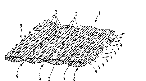
Figure l shows a two-layered reinforced fibre structure before
placing the fillers.5 Figure 2 shows a finished laminating reinforced fibre struc-
ture.
Figure 3 shows a reinforced fibre structure formed on a mold. Figure 4 shows a finished formed reinforced fibre piece.
Figure 5 shows one possible way of manufacturing thicker
pieces.
~igure 6 shows a beam structure formed with the aid of a
reinforced fibre structure in accordance with the
in~ention.
Figure l shows a two-layer reinforced fibre structure, through
the layers may be more in number. What is essential is that the
layers 7 and 8 on top of ~ne another continually change sides
in such a way that their warps 2 run in turn in the upper and
lower layers. Their cross points, i.e. points of changing side,

WO93/05219 21 1 6 9 7 8 PcT/Fl9~/~o24l
are formed by ties 9, between which several fibres remain. Here
the warps and wefts are formed of suitable bundles of fibres.
Glass ~ibres are typically used. Aramid, carbon, ceramic, or
other reinforcing fibres may also be used.
The filler pieces must not absorb resin completely, so that the
finished product will be light. Fcam plastic fillers permit good
dampness; heat, and sound insulation. If required foam-type
fillers can be removed from a laminated piece.
One or several common weft yarns can also be used as binding
- points.
. .
.
A reinforced fibre structure in accordance with Figure 1 is
taken to the next st~ge, in which the ties 9 and the inwardly
closing channels of the layers 7 and 8 are filled with fill~r
4, which may be hollow pieces 4', for examples plastic pipes or
foam plastic pieces 4". It is advantageous to use closed-cell
foam plastic, for example polythene, which does not absorb
resin. Other plastics and rubber can also be considered. These
pieces do not necessarily need to be round, but can possibly be
of some other cross-s~ctional form.
The reinforced fibre structure can contain, in addition to the
structure in accordance with Figure 1, either on one or both
sides even layers, which are loosely bound to these layers from
between the ties. By means of them it is possible to obtain a
~ gréat strength in the direction of the surface.
The fibre structure in accordance with Figure 2 with its fillers
is treated with resin and is set in the mold 6 in accordance
with Figure 3. The fillers 4 flex and permit the reinforced
~ibre str~cture 1' to csnform ts the shape of the mold.
Figure 4 shows a finished reinforced fibre structure. The
fillers 4 excep~ one have been remo~ed. In a corresponding way
it i~ possible to form an arbitrarily formed piece. If a thicker
piece is decired layer folding in accordance with Figure 5 can
be used, or struc~ures in accordance with Figure 2 can be laid

W093/05219 PCT/Fl92J00241
211~97~
on top of one another at a suitable angle to each other. The
fibre structure can be manufactured in varying thickness to
minimize formin~.
Heat-forming technique can also be exploited in the reinforced
fibre structure in accordance with the invention. A binding
subs~ance, for example polyester, is ~dded to the bundles of
fibres that run in a vertical direction to the ties, when after
weaving the channels are filled with a core, which temporarily
forms the aforementioned filler. The binding substance can then
be melted momentarily with the aid of heat, when a cell
structure blank is formed. The intention of the binding
substance is to provide the reinforcing fibres with a suitable
stiffness for sufficiently long for the laminating blank to be
pressed in the mold into the desired form.
The foam plastic filler may be a thermoplasticly treated
material, for example polythene, when pieces of the desired
shape are manufactured in the mold with the aid of heat
treatment to be laminated.
In the laminating stage the prepreg technique, which is as such
known, can be used.
Between the ties there may be a varying amount, typically lO -
25, of bundles of yarn running in the direction of the ties. In
the test piece the polythene pieces have been of a diameter of
20 mm. In these normal glass fibre fabric (TEX 2400) was
used, which was, however, woven together with the second layer
in a manner in accordance with the invention. Using at least a
5 mm diameter a unique structure is provided.
_.. ~
Wood or metal can be used as materials for the fillers,
especially to create adhesion in a laminating piece. A
particularly interesting possibility is to use an expanding
~ompact material as a filler. In this case for example the
~illers expand due to the heat o the mold and raise the
structure to become s~iff.

Representative Drawing
A single figure which represents the drawing illustrating the invention.
Administrative Status

2024-08-01:As part of the Next Generation Patents (NGP) transition, the Canadian Patents Database (CPD) now contains a more detailed Event History, which replicates the Event Log of our new back-office solution.

Please note that "Inactive:" events refers to events no longer in use in our new back-office solution.

For a clearer understanding of the status of the application/patent presented on this page, the site Disclaimer , as well as the definitions for Patent , Event History , Maintenance Fee  and Payment History  should be consulted.

Event History

Description Date
Inactive: IPC from MCD 2006-03-11
Application Not Reinstated by Deadline 2000-09-11
Time Limit for Reversal Expired 2000-09-11
Inactive: Abandon-RFE+Late fee unpaid-Correspondence sent 1999-09-13
Deemed Abandoned - Failure to Respond to Maintenance Fee Notice 1999-09-13
Application Published (Open to Public Inspection) 1993-03-18

Abandonment History

Abandonment Date Reason Reinstatement Date
1999-09-13

Maintenance Fee

The last payment was received on 1998-08-28

Note : If the full payment has not been received on or before the date indicated, a further fee may be required which may be one of the following

  • the reinstatement fee;
  • the late payment fee; or
  • additional fee to reverse deemed expiry.

Please refer to the CIPO Patent Fees web page to see all current fee amounts.

Fee History

Fee Type Anniversary Year Due Date Paid Date
MF (application, 5th anniv.) - small 05 1997-09-11 1997-08-12
MF (application, 6th anniv.) - small 06 1998-09-11 1998-08-28
Owners on Record

Note: Records showing the ownership history in alphabetical order.

Current Owners on Record
FINNCLEVER OY
Past Owners on Record
MAURI LAITINEN
Past Owners that do not appear in the "Owners on Record" listing will appear in other documentation within the application.
Documents

To view selected files, please enter reCAPTCHA code :


To view images, click a link in the Document Description column. To download the documents, select one or more checkboxes in the first column and then click the "Download Selected in PDF format (Zip Archive)" or the "Download Selected as Single PDF" button.

List of published and non-published patent-specific documents on the CPD .

If you have any difficulty accessing content, you can call the Client Service Centre at 1-866-997-1936 or send them an e-mail at CIPO Client Service Centre.


Document
Description 
Date
(yyyy-mm-dd) 
Number of pages   Size of Image (KB) 
Claims 1993-03-18 3 107
Abstract 1993-03-18 1 69
Drawings 1993-03-18 3 90
Cover Page 1993-03-18 1 26
Descriptions 1993-03-18 4 236
Representative drawing 1998-07-21 1 22
Reminder - Request for Examination 1999-05-12 1 118
Courtesy - Abandonment Letter (Maintenance Fee) 1999-10-12 1 184
Courtesy - Abandonment Letter (Request for Examination) 1999-10-25 1 172
Fees 1998-08-28 1 34
Fees 1997-08-12 1 36
Fees 1996-08-28 1 34
Fees 1995-08-28 1 39
Fees 1994-08-26 1 45
International preliminary examination report 1994-03-03 9 273