Note: Descriptions are shown in the official language in which they were submitted.
F
2~.1~~~
- 1 -
AN IMPROVED RADIAL PLY TIRE
Baelccrround of the Invention
This invention relates to pneumatic radial ply
tires and the interrelationship between the tire and
its design rim.
Historically, with the introduction of the
tubeless type tire, the design fitment of the bead
portions of the tire to the design rim has increased
in significance. This fitment insures that the tire
remains air tightly sealed and securely fixed to the
rim during vehicle use.
The typical rim has a bead seat and a rim flange
that defines the contact zone with the tire bead. The
tire bead has an annular surface between the bead heel
and bead toe that upon assembly to the rim contacts
the bead seat. The bead also has an annular surface
radially outwardly of the bead heel, this annular
surface contacts the rim flange when the tire is
mounted and inflated on the rim.
The prior art teaches the use of a rim with
cylindrical or very slightly conical bead seats.
Typically such bead seats were inclined at an angle of
5° relative to the axis of rotation of the tire. To
ensure a proper fitment, the tire beads had an annular
surface having a similar 5° inclination relative to
the axis of rotation, the beads having a slightly
smaller diameter than the rim seat, thus upon
assembly, a snug interference fit would be achieved.
Such a prior art tire is shown in Figure 3A.
As a later development, the radially innermost
flexible toe portion of the tire between the toe and
the annular tensile member comprised an inclined
surface about 5° greater than the rim seat. This
- 2 -
added interference created by the angular variation
facilitated sealing the tire. This prior art tire is
illustrated in Figures 3B and 3C.
The prior art tires hacL beads with a surface
radially outwardly of the bead heel. This surface
ideally should contact the rim flange, both the rim
flange and this axially and radially outwardly surface
being oriented at 90° relative to the wheel axis.
This area being under pressure while the tire is
inflated over a portion of its surface, contacts the
rim flange essentially fastening the tire on the rim.
The prior art tires essentially relied on the rim
seat and flange orientation to establish the shape and
orientation of the bead, with the exception being the
flexible toe portion of the bead.
Surprisingly it has been discovered that the
prior art tire bead designs have a less than ideal
fitment to the rim, particularly in the rim flange
area of the J type rims. Those skilled in the art
have believed that the surface radially outward of the
bead heel was in firm surface contact with the rim
flange. In fact, tangential x-rays indicate that a
portion of this flange surface area is actually spaced
from the rim creating a gap and, therefore, is of no
assistance in firmly fixing the tire to the rim.
It has been discovered that a tire made according
to the present invention, having unique bead surfaces
for contacting the rim can result in a tire having,
improved lower sidewall stiffness, better rolling
resistance and improved comfort. A tire made
according to the present invention can exhibit
uniformly low bead seating forces when mounted to the
rim, yet also exhibit superior adhesion of the tire to
the rim.
CA 02117049 2002-02-08
- 3 -
Summary o~ the Invention
According t:o ome aspect of the present invention
there is provided am improved radial-ply pneumatic tire
having an axis or rotation, and a pair of axially-spaced
beads respecti~rely -including annular t:ensilE:~ members,
each annular tc~nsilEe member having a z~adia_Lly inner flat
surface prior t:o them tire being moldecL, an<i at least one
radial ply extcendinc~ between the annular tensile members
of the respect ~ve bE~ads, tree beads each having a heel
portion and a l:oe portion designed to engage a design rim
having a bead ,>eat ~~nd a design rim width D, the width D
being defined ,~s half of the quantity equal to the
maximum recommended wim width plus the minimum
recommended rim width, such rim widths being as specified
by the industry star~dards in effect in the location in
which the tire is manufactured, the improved tire being
characterized ioy a f'i.rst annular surface between the heel
and toe of eacri bead and a second annular surface
extending radi~lly outwardly from each bead heel, the
first annular ~=surface being in full contact with the bead
seat of the den=ign rim when t:he tire is mounted and
inflated to nominal pressure, t:he first annular surface,
when the tire Zs unmounted, f=arming, with the axis of the
tire, when the beads are axially spaced a distance equal
to the design tire width D, an average angles, that is in
the range of or,e-half degree to less than three degrees
greater than true angle formed between the mating bead
seat of the design rim and the axis of the tire, and the
second annular surface when the tire is unmounted is
inc:iined at an angle that is in the range of 0° to less
than 3° relativf~ to a plane P, the plane P being
perpendicular to the axis of rotation, the second annular
surface being in contact with an annular flange portion
of t=he design rim when the tire is mounted and inflated
CA 02117049 2002-02-08
- 4 -
than 3° relativE~ to a plane P, the plane P being
perpendicular to the axis of rotation, t=he second annular
surface being in contact with an annular flange portion
of t=he design rim when the t=ire i.s mounted and inflated
to normal pressure and wherein the beac:l is gE:nerally
uniformly radially compressed between the :first annular
surface and the <~nnuLar tensile member as measured
between an axially inner and an axially outer end of the
radially inner Elat ,surface of the annular tensile
member, the compression being measured as a ~~ercentage of
tad=Lal compression when the t=ire is mounted to its design
rim.
A portion ~f th~~ first annular sumface, when the
beads are to th~= design rim width, is located
between a plane <~ perpendicular to the axis of the tire
and passing through ~~he center of the annular tensile
member, and a plane 'r tangent to the axially outer side
of the annular ~ensi::Le member and perpendicular to the
axis of rotatio:2 of t=he tire.
Preferably, the angle (B is in the range of 5°30' and
less than 8° reLativf~ to a _Line parallel. to the axis of
rotation. Most orefe=_rably ~~ is about 6°?0' greater than
the angle forme<~ between the bead seat of the design rim
and a line parallel too the axis.
Ideally, the first annu)_ar surface is oriented at
the angle (3 at Least over the distance between the plane
T and a plane S, the plane S being tangent to the axially
inner side of tine ammlar tensile member and
perpendicular to the axis of rotation of the tire.
CA 02117049 2002-02-08
- 4a -
A tire having the bead seat oriented at the angle
and employing a;z annular tensile membe~:~ formed with a
flat base when ~~ombimed with a rim hav~.ng a 5° bead seat
area yields generally uniform compression of the material
between the tensile member and the bead seat. This
uniform compres:~ion enables t=he tire to be built
requiring low and uniform bead seating force's while at
the same time yielding improved adhesion of the tire to
the rim.
In the preferred embodiment, the f_i_rst ~;urface is
inclined at an angle (3 and extends axially outwardly of
the plane T. Th~~ fir;:~t surface intersects with the heel,
the heel having a single radius of curvature. The heel
curvature extent's ax_Lally and radially outwardly and is
tangent to the ,~econc3
CA 02117049 2002-02-08
- 5 -
surface. The second surface extends radially
outwardly preferably perpendicular to the axis of
rotation to a third surface, the third surface being
curved and having a radius of curvature at least equal
to or greater than the radius of curvature of the
design rim flange.
Definitions
"Aspect ratio" of the tire means the ratio of its
section height (SH) to its section width (SW)
multiplied by 100% for expression as a percentage.
"Axial" and "axially" means lines or directions
that are parallel to the axis of rotation of the tire.
"Bead" means that part of the tire comprising an
annular tensile member wrapped by ply cords and
shaped, with or without other reinforcement elements
such as flippers, chippers, apexes, toe guards and
chafers, to fit the design rim.
"Belt structure" or "Reinforcing Belts" means at
least two annular layers or plies of parallel cords,
woven or unwoven, underlying the tread, unanchored to
the bead, and having both left and right cord angles
in the range from 17 degrees to 27 degrees with
respect to the equatorial plane of the tire.
"Carcass" means the tire structure apart from the
belt structure, tread, undertread, and sidewall rubber
over the plies, but including the beads.
"Circumferential" means lines or directions
extending along the perimeter of the surface of the
annular tread perpendicular to the axial direction.
"Cord" means one of the reinforcement strands of
which the plies in the tire are comprised.
"Design rim" means a rim having a specified
configuration and width. For the purposes of this
Specification, the design rim and design rim width are
6 -
as specified by the industry standards in effect in
the location in which the tire is made. For example,
in the United States, the design rims are as specified
by the Tire and Rim Association. In Europe, the rims
are as specified in the Euro~oean Tyre and Rim
Technical Organisation - Standards Manual and the term
design rim means the same as the standard measurement
rims. In Japan, the standard organization is The
Japan Automobile Tire Manufacturer's Association.
"Design rim width" means the specified distance
axially between rim flanges. Fox the purpose of this
specification, the design rim width (D) is taken as
(the minimum recommended rim width plus the maximum
recommended rim width)/2 as specified by the
appropriate industry standards.
"Equatorial plane (EP)" means the plane
perpendicular to the tire's axis of rotation and
passing through the center of its tread.
"Innerliner" means the layer or layers of
elastomer or other material that form the inside
surface of a tubeless tire and that contain the
inflating fluid within the tire.
"Normal inflation pressure" refers to the
specific design inflation pressure and load assigned
by the appropriate standards organization for the
service condition for the tire.
"Normal load" refers to the specific design
inflation pressure arid load assigned by,the
appropriate standards organization for the service
condition for the tire.
"Ply" means a continuous layer of rubber-coated
parallel cords.
"Radial" and "radially" means directions radially
toward or away from the axis of rotation of the tire.
-
"Radial-ply tire'° mean~o a belted or
circumferentially-restrictecL pneumatic tire in which
the ply cords which extend from bead to bead axe laid
at cord angles between 65° and 90° with respect to the
equatorial plane of the tire'.
"Section height" (SH) means the radial distance
from the nominal rim diameter to the outer diameter of
the tire at its equatorial plane.
"Section width" (SW) means the maximum linear
distance parallel to the axis of the tire and between
the exterior of its sidewalls when and after it has
been inflated at normal pressure for 24 hours, but
unloaded, excluding elevations of the sidewalls due to
labeling, decoration or protective bands.
"Sharp diameter" means the diameter as measured
radially across the tire through the axis to the
points defined by the intersection of a line extending
tangent the bead seat or first surface and a line
extending tangent the bead flange or second surface.
"Shoulder" means the upper portion of a sidewall
just below the tread edge. Affects cornering.
"Sidewall" means that portion of a tire between
the tread and the bead.
"Tread width" means the arc length of the tread
surface in the axial direction, that is, in a plane
passing thxough the axis of rotation of the tire.
Detailed Description of the Drawings
Figure 1 is a cross-sectional view of the
preferred tire made in accordance with the invention.
Figure 2 is a cross sectional view of a standard
design rim.
Figure 3A is a cross sectional view of a first
prior art tire.
~~.~ s~~~
Figure 3B is a cross sectional view of a second
prior art tire.
Figure 3C a.s an enlarged crass sectional view of
a bead taken along lines 3C of Fig. 3B.
Figure 4 is an enlarged cross sectional view of a
bead taken along lines 4-4 of Fig. 1.
Figure 5 is a cross sectional view of the prior
art tire of Figure 3B mounted and inflated on a design
rim.
Figure 5A is an enlarged view of the prior art
tire of Figure 3B as taken along lines 5A of Figure 5.
Figure 6 is a cross sectional view of the tire of
Figure 1 according to the present invention mounted
and inflated on a design rim.
Figure 6A is an enlarged view of the tire of
Figure 1 as taken along lines 6A of Figure 6.
Figure 7 is a table of the tire and rim fitment
of the tires of Figures 5 and 6 when mounted to rims
having design widths of 6, 7, 8 and 9 inches (152,
179, 203 and 229 mm).
Figure 8 is an enlarged cross sectional view of
the prior art tire bead.
Figure 8A is a table showing the compression
results when the prior art tire is mounted on the
design rim.
Figure 9 is an enlarged cross sectional view of
the tire bead according to the present invention.
Figure 9A is a table showing the compression
results when the tire of the present invention is
mounted on the design rim.
Figure 10A is a table of the bead compression
force (Newtons) as a function of bead displacement at
various bead diameters.
~.~~~4 ~~
_ g _
Figure 10B is a table of the bead compression
force (Newtons) as a function of bead displacement at
various bead diameters.
Figure 11 is a table demonstrating the range of
bead seat inflation of the prior art tire versus the
tire of the present invention.
Figure 12 is a table demonstrating the bead
durability of the prior art tire versus a tire of the
present invention.
Figure 13 is a table demonstrating the rim slip
exhibited by the prior art tire versus a tire
according to the present invention.
Detailed Description of the Invention
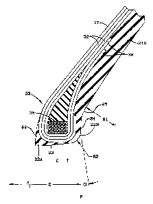
Referring to Figure 1, there is illustrated a
cross sectional view of a tire made in accordance with
the present invention. In the particular embodiment,
the tire 30 is a low aspect ratio passenger tire. As
shown, the beads 33 are spaced axially a distance (D)
equal to the specified design rim width.
The tire 30 is provided with a ground-engaging
tread portion 31 which terminates in the shoulder
portions 32 at the lateral edges of the tread.
Radially outer sidewall portion 21 extends from
shoulder portion 32 and terminates in the bead portion
33, the bead portion having an annular inextensible
annular tensile member 35. The tire 30 is further
provided with a carqass reinforcing structure 36 which
extends from the tensile member 3S through the
sidewall portion 21, the tread portion 31, the
opposite sidewall portion 21 down to the opposite
tensile member 35. The turnup ends 38 of the carcass
reinforcing structure 36 are wrapped about the tensile
members 35. As illustrated, the bead portion 33 has a
chipper 41 wrapped about the reinforcing member 36 and
~~d.rj~l~~
- 10 -
tensile member 35. The tire 30 may include a
conventional innerliner 37 forming the inner
peripheral surface of the t~.re 30 if the tire is to be
of the tubeless type.
Placed circumferentially about the radially outer
surface of the carcass reinforcing structure 36,
beneath the tread portion 31, is a tread reinforcing
belt structure 39. In a preferred embodiment, the
belt structure 39 comprises two single cut belt plies
and the cords of the belt plies are oriented at an
angle ranging between 17° and 25° with respect to the
equatorial plane of the tire. The cords of one belt
ply are disposed in an opposite direction to the
equatorial plane and from that of the cords of the
other belt ply. However, the belt structure 39 may
comprise any number of belt plies of any desired
configuration and the cords may be disposed at any
desired angle.
The carcass reinforcing structure 36 includes at
least one reinforcing ply structure comprising each
one layer of parallel cords. The cords of the
reinforcing ply structure 36 are oriented at an angle
of at least 75° with respect to the equatorial plane
EP of the tire 30. The cords reinforcing the carcass
ply may be of any material normally used for cord
reinforcement of rubber articles, for example, and not
by way of limitation, rayon, nylon and polyester. The
reinforcing ply gtructure 36 has its turnup ends 38,
which wrap about the bead core 35, located at about
20-°s to 50% of the section height of the tire.
Before mounting the tire 30 on a rim and
inflating it, it has the shape imparted to it by the
mold. After mounting the tire 30 on the rim, the
inclination of the bead portions of the tire is
imposed by the rim.
~~.IPIO~
- 11 -
The bead 33 has a first annular surface 23
located between the bead toe 22A and the bead heel
22B. The first annular surface is inclined at an
angle (3~ when the beads 33 a:re spaced a distance D.
The distance D is defined as the design rim width D or
the molded bead width D. For the purpose of this
specification, the design rim width (D) is the average
of the specified maximum and minimum design rim
widths, the widths being measured axially between the
rim flanges. The range of design rim widths is
established by the industry standards applicable where
the tire is made. In the United States, for example,
the Tire and Rim .Association standards have
established a range of recommended rim widths for "J"
type rims in the 14" to 16" rim diameter size, the
range of widths for a 225/55816 tire being 6.5 to 8.0
inches. The design rim width as defined in the
application, therefore, is 7.25 inches for the
225/55816 tire. A tire molded at a different bead
width naturally may have different bead surface
orientations. However, when the beads are spaced a
distance D as so defined, the orientation of the
surfaces must fall within the range to achieve the
benefits of the present invention.
The bead portion 33 has a second annular surface
24 that extends radially outwardly from the bead heel
portion 22B. The second surface 24 is oriented
preferably perpendicular to the axis of rotation when
the beads 33 are spaced at the design rim width D.
Extending :From the second surface 24 is a curved third
surface 25. The third surface 25 tangentially
extending :From the second surface 24, preferably has a
single radius of curvature R1. The curvature R1 is at
least equal to or larger than the curvature of the
design rim's flange. The curvature R1 is preferably
CA 02117049 2002-02-08
- 12 -
centered radially about .375 inches above the nominal
diameter of the tire for a 14" or 16" "J" type rim.
This positioning locates the third surface radially
tangent or outward of the rim flange when the tire is
mounted onto the design rim and inflated to normal
pressure.
In the preferred embodiment, the lower sidewall
portion 21H has a radius of curvature that is tangent
to, and extends radially outward from, the third
surface 25.
In Figure 2, a design rim 40 is shown. The
design rim has a bead seat 42 inclined at an angle ~BR
relative to the axis of rotation and a flange 44
oriented at an angle aR, aR, being nominally
perpendicular to the axis of rotation. The angle
is nominally 5° as shown. Between the flange 44 and
the bead seat 42, the rim has a radius of curvature
RR1. At the radially outer portion of the rim flange
44, the surface of the flange has a radius of
2 0 curvature R~ .
Figure 3A illustrates a conventional prior art
tire 10 having a pair of beads 13 with each bead
having an annular tensile member 15, a reinforcing ply
16 wrapped about and extending from each of the
tensile members 15, a radially outer tread 11, belt
reinforcement 19 and a pair of sidewalls 6 extending
from the tread 11 to the beads 13. As illustrated,
the beads 13 when spaced to the design rim width D
have an annular surface 3 extending between the bead
heel 2 and toe 1, the annular surface 3 being oriented
at an angle /3R of about 5° or identical to the rim
bead seat 42 orientation. Additionally, the prior art
tire as illustrated has a radially outwardly extending
surface 4, the surface 4 extending from the bead heel
2 and being oriented 90° to the axis of rotation.
~~.1'~~~~
- 13 -
Figure 3B illustrates a second prior art tire 130
having a pair of beads 133, each bead having an
annular tensile member 135, a reinforcing ply 136
wrapped about and extending from each of the tensile
members 135, a radially outer tread 131, belt
reinforcement 139 and a pair of sidewalls extending
from the tread 131 to the beads 133. As illustrated
in Figure 3C, the beads 133, when spaced to the design
rim width D, have a first annular surface 123
extending between the bead heel 122B and toe 122A.
The first annular surface 123 has a first portion 123A
extending from the bead heel 122B to a point C about
axially aligned with the axial center of the bead 135,
the first portion 123A being oriented at 5° relative
to the axis of rotation. The first surface 123
further has a second portion 123B extending from the
first portion 123A, the second portion 123B being
inclined at an angle of 10.5° relative to the axis.
The second portion 123B extends axially inwardly to a
curved third portion 123C, the third portion 123C
being adjacent the toe and having a radius of
curvature of R3. The three portions of the first
surface 123 and the radially inner surface of the heel
122B comprise the bead seat surfaces. The bead
portion 133 of the prior art tire 130 further includes
a radially outwardly extending second surface 124, the
second surface 124 extending from the bead heel 1228
and oriented. perpendicular to the axis of the tire
130. A curved third surface 125 extends from the
second surface 124 to the lower sidewall portion 221B.
The third surface has a single radius of curvature R1.
The tire 130 having a compound first surface 123 with
increased inclination between the toe 122B and the
first portion 123A was designed to enhance air tight
sealing and adhesion of the tire 130 to the rim 40.
' 2~~.~1~~~3
- 14 -
The increase in angular inclination, particularly
directly radially inward of the bead tensile member,
meant that the percent of compression of material
between the bead 133 and the rim 40 varied greatly
upon assembly. This variation of compressed material
in combination with the normal tolerances involved in
the manufacturing process results in a wide range of
bead seating force and is a contributor to tire fit
nonuniformity.
As shown in Figure 4, an enlarged bead portion 33
made according to the present invention is positioned
at the axially spaced distance equal to the design rim
width D. Between the axially outer bead heel 22B and
the axially inner bead toe 22A is a first annular
surface 23. The first annular surface 23 is inclined
at an angle a relative to a line parallel to the axis
of rotation of the tire 30. The angle ~i is preferably
in the range of 5°30' to less than 8°, more preferably
between 6° and 7°. When mounted to the rim 40 having
a aR inclination of 5°, the angular variation between
a and ~3R is 0°30' to less than 3°, preferably about
1.5° angular variation.
In addition to this angular variation, the tire
according to the present invention has a second
25 annular surface 24 radially outwardly of the bead heel
22B. The second annular surface 24 is in contact with
the annular flange portion 44 of the design rim 40
when the tire 30 is mounted and inflated to normal
pressure. The second annular surface 24 is preferably
30 oriented at an angle a, a being perpendicular to the
axis of rotation. Alternatively, a can be
substantially equal to the angular difference of the
first annular surface a minus the bead seat
orientation of the rim /3r. This means that ~ can be
inclined in the range of 0° to less than 3° from the
- 15 -
perpendicular plane P, preferably 0° to 1.5° off
perpendicular.
In order to precisely measure the bead surfaces,
it is recommended that the unmounted and uninflated
tire 30 have its beads 33 positioned at the specified
design rim width of the tire. Next two reference
points on the bead must be established the two points
being in the same cross sectional plane. The first
point is suggested to be at the bead toe 22A and the
second point anywhere along the second annular
surface. By measuring from a fixed distance from the
axis of rotation of the tire, a reference line can be
established parallel to the axis of rotation. The
tire bead being reasonably dimensionally stable can be
cut from the tire in cross sections such that the two
marked reference points are in the same plane. By
reestablishing the reference line, the same
orientation of the annular tire with its bead located
at the design rim width is achieved when the two
reference points are positioned the exact radial
distance above the reference line. It should be noted
the reference line may be at the axis of rotation or
any convenient line parallel to the axis and lying in
a plane between the axis and the two reference points.
Once the dimensional reference is reestablished,
' the exact orientation of the annular first and second
surfaces 23 and 24 can be measured. This method of
measurement may be further enhanced by employing a
comparator which enlarges the bead cross section and
facilitates more accurate measurements. The
measurement techniques are known in the art and can
lead to very accurate measurement, even of elastomeric
composite articles such as tires.
In Figure 5, a prior art tire is shown mounted
and inflated on a design rim 40. An enlarged view,
- 16 -
Figure 5A, illustrates the bead and rim fitment.
Point A represents the toe of the tire. Point D
represents the radially outermost surface of the bead
portion in contact with the flange. The annular
surface area between Point A and Point D represents
the maximum possible rim contacting area available for
the prior art tire. As can be seen, the area between
Point C and Point B is where the tire bead and the rim
are gapped. This means that the adhesion between the
rim and the tire is not at 100% of its maximum
potential.
Figures 6 and 6A are of the tire according to the
present invention. The tire fits the rim from Point A
to Point D with virtually no gap.
Tires of a given nominal rim diameter must be
able to fit rims having a range of rim design widths.
A control tire according to the prior art as shown in
Figs. 5 and 5A was made in the 225/55816 size. The
control tire was molded with an 8.0 inch molded bead
width. The tire had a 16.14 inch tensile member 35
inside diameter hereinafter referred to as the bead
diameter. The sharp diameter was 15.908 inches.
Similarly, an experimental tire made according to the
present invention was fabricated. The 225/55816
experimental tire had a 7.25 inch molded design rim
width (D) or mold bead width, a 15.923 inch sharp
diameter, and a bead diameter of 16.18.
Conventional "J," type rims having a 5° bead seat
were mounted with the control tires and experimental
tires. The rim widths ranged from 6" to 9" in one
inch increments. Tangential X-rays were taken of each
tire and rim assembly at two locations 180° apart for
each side of the tire. The gap at each of the four
locations was measured from the X-ray film and the
average amount of gap was then calculated. The
- 17 -
results are as shown in Fig. 7. The results as
illustrated are the axial space between the second
annular surface and the x~im flange unless indicated by
an °H" which is the gap at the heel radius and the rim
heel radius. Although the present invention attempts
to eliminate all gaps, gaps at the heel radius are
considered acceptable due to the minimal surface area
and the inability of the stiff bead to conform into
the rim contour over the entire range of rim widths.
As can be readily seen from the table of Fig. 7,
the prior art control tire is gapped on rim widths of
6, 7, and 8 inches along the rim flange and is gapped
in the heel area on the 9 inch size rim width.
Alternatively, the experimental tire made according to
the present invention exhibits no rim flange area
gapping and only a minor average gap is shown in the
bead heel radius area for the 8" and 9" rim widths.
The improved fit is believed to be the result of the
change in bead shape in combination with the molded
bead width change. The increase in the bead diameter
and the change in sharp diameter are believed to be of
importance to fit but of greater importance to bead
seat force and uniformity of compression as will be
discussed below.
One factor that is believed to contribute to the
poor fit relationship by the prior art control tire
130 and other commercially available tires is that as
the rim width.differs from the molded bead width, the
curved third surface 125 of the bead contacts the
curved portion of the rim flange. This is
particularly problematic when the rim width is axially
smaller than the tire's molded bead width. In that
case, the curvature of the third surface 125 is in
fact radially lowered contacting the rim flange at the
curvature of the flange at a location as shown in Fig.
- 18 -
5A initially at Point C. This axially pushes the
entire bead inwardly and creates the gaps as noted in
the table of Fig. 7. Alternatively, the present
invention has the molded design rim width D selected
to minimize the axially inward shift and the bead
shape is such that the curved third portion 25 extends
from the second surface 24 a distance spaced
sufficiently radially outwardly to insure that the
radius of curvature of the third surface 25 is at
least radially spaced equal to or greater than the
radius of curvature of the design rim flanges over the
range of recommended widths. Under these dimensional
conditions, the curvature cannot push the bead axially
inwardly thus creating a gap along the second annular
surface as is exhibited in the prior art tires.
Figs. 8 and 9 respectively illustrate a portion
of the bead 133 of the prior art tire 130 and a
portion of a bead 33 of the present invention tire 30
in solid lines with the design rim 40 shown in dashed
lines. The bead annular tensile number 35 in both
figures has a rectangular cross section. Plane T
represents the axially outer portion of the annular
tensile member 35 while Plane S represents the axially
inner location of the tensile member 35, each plane
being tangent to the tensile member's axially inner
and axially outer ends and perpendicular to the tire's
axis. The bead's annular tensile members 35 are
formed from steel filaments annularly wrapped in
layers, commonly known in the art as a strap bead.
The radially inner surface of the annular tensile
member 35 as shown is a horizontal surface parallel to
the axis of rotation of the tire. Alternatively, the
tensile member could have a hexagonal, square, or
other cross sectional shape having a radially inner
flat or horizontal surface.
- 19 -
As illustrated in Figs. 8 and 9, the prior art
tire 130 and the tire 30 of the present invention have
an interference fit between the design rim bead seat
42 diameter and the bead 33,133 of the tires. The
interfering material as illustrated must move or be
compressed. The annular tensile member being
virtually inextensible means that the material
directly radially inward of the member 33 must be
compressed.
Tn Figs. 8A and 9A, tables of engineering
calculations are shown. The prior art tire and the
tire of the present invention when designed to fit on
a 14" nominal diameter "J" type rim exhibits the
dramatic differences in the percentage of material to
be compressed.
As shown in table 8A, the prior art tire at
locations B, C and D has percentage of material
compression of 21.5%, 25.30 and 28.5% respectively. A
difference of 7o is exhibited. This percentage
difference greatly affects the force required to seat
the beads when mounting the tire to the rim. The
ideal situation is believed to be exhibited when the
percentage compression is constant between the B, C
and D locations. The 7% range when divided by the
mean percent material compression shows a 28% range
variation from high to low.
As shown in Fig. 9A, the tire according to the
present invention between planes S and T at locations
B, C and D has a generally uniform percentage of
material radially compressed of 21.20, 21.4% and 21.5--°s
respectively. A difference of only 0.3o is exhibited.
This small percentage change will be shown in a later
table to dramatically reduce the amount of inflation
pressure required to seat the beads upon a rim.
Although not an ideal constant percentage compression,
~~~.1~~
20 -
the variation of 0.3% across the range when divided by
the mean percentage material compression yields less
than 1.5o range variation from the high to low. The
percentage compression variation between planes S and
T is one percent or less from the mean or average
compression when the tire 30 is mounted on its design
rim. Preferably, the bead percentage of compression
is less than 22o between planes S and T.
The effect of this improved compression
uniformity can best be observed in Figs. 10A and 10B.
Figs. 10A and 10B illustrate graphically the effect of
the material compression variation.
In Fig. 10A a 225/60816 control tire is compared
to a 225/60816 test tire made according to the present
invention. Each tire had bead diameters of 16.14
inches. The control tire exceeded the ideal value,
whereas the test tire has a shallower slope and is
slightly below the ideal value. This means that the
force required to seat the beads is lower in the test
tire than the control tire.
The control tire ideally should require 2500
Newtons or 550 pounds to seat the beads upon the 16.0'°
nominal diameter rim. When the prior art 225/55816
control tire of Fig. 10B has a 16.14 bead diameter and
a nominal sharp diameter of 15.908 inches at a point
approximately -0.015 inches (-4 mm), the curve crosses
the ideal value. At the nominal sharp diameter, the
force required is about 3300 Newtons. The box
represented by the dashed lines establishes an
acceptable range of force versus bead displacement
relative to the nominal sharp diameter. Ideally, the
curare should enter and leave the box intersecting the
vertical walls.
From Fig. 10B, the curve of the 225/55816 control
tire, one can see that the slope is quite high and
,,
21 -
that the nominal sharp diameter should be increased
from 15.908 by .015 inches or 4 mm. This increase to
15.923 would mean that the .ideal force value should be
at the new nominal sharp diameter value.
In Fig. 10B, a prior a:rt control tire having a
16.14 inch bead diameter was compared to four test
tires made according to the present invention. The
curves of the test tire have the nominal sharp
diameter increased by the .015 inch. Correspondingly,
the nominal bead diameters were correspondingly
increased in .020 of an inch increments from 16.16 to
16.22 inches. Interestingly, the 16.16 diameter
225/55816 test tire fell precisely on the ideal 2500
Newton force line. The lower 55 aspect ratio tire of
Fig. lOB being stiffer than the 60 aspect ratio tire
of Fig. 10A explains the slightly higher bead seating
of the lower aspect ratio tire. The curves of the
1&.16, 16.18 and 16.20 bead diameters were
surprisingly closely spaced while the curve for the
16.22 test tire was more widely spaced. The curves of
the test tires, when compared to the control tire,
each exhibited a shallower slope of forces which is
believed to, be directly related to the uniform
compression under the bead tensile member 35 when the
first annular surface 23 is inclined at the preferred
angle ~3 of 6 . 5 ° .
Of even greater significance, by employing the
present invention and shifting the bead,diameter to
16.18 inches, a plus or minus .020 inch variation of
tolerances can be absorbed without significantly
changing the bead seat force. This means that the
tire made according to the present invention is much
less tolerance sensitive when compared to those of the
prior art. Preferably the annular tensile member has
a radially inner surface having a diameter in the
~~~6~~
22 -
range of 0.14 to .22 inches (3.5 mm to 5.6 mm) greater
than the nominal diameter of the rim for which the
tire is intended to be mounted.
Naturally, one of ordinary skill in the art would
suspect the increase in bead diameter to result in
lower forces to seat the beads onto the rim when
mounting the tire. However, a corresponding effect of
a reduced tire to rim adhesion would be expected.
Historically, the tire engineer has opted for
increasing interference between the tire and rim to
maximize adhesion as evidenced by the prior art tires.
The present invention relies more on uniform
compression and maximizes the rim to tire bead surface
contact and adhesion.
Fig. 11 shows that the 225/55816 prior art tire
130 requires between 39 and 45 psi to seat the beads
upon mounting. The present invention tire requires 24
to 25 psi to similarly seat the beads. The tires were
then tested for rim slip under breaking and
acceleration tests which will be further discussed.
Neither the prior art tire nor the tire of the present
invention exhibited rim slip.
Tire/rim slippage is more severe when certain
lubricants are used to seat the beads. Fig. 13 is a
table wherein tires of the P225/60R16 size were
evaluated using the prior art bead shape of Fig. 3
versus the bead shape of the present invention. In
this test, the bead diameters of both the control tire
and the test tire were identical, 16.14 inch
diameters. The total amount of tire-to-rim slippage
under wide open throttle acceleration from a stopped
position as well as breaking slip was tested. The
results measured in inches of slip are the total slip
observed in three successive runs. The tire and rim
were each marked and the circumferential distance
- 23 -
between the marks was measured after the tests. The
position relative to the vehicle is indicated, RR
meaning right rear, RF meaning right front. In
acceleration tests, the rear tires were much more
prone to slippage as would be expected of a rear wheel
drive vehicle. The experimental tire was
substantially better than the control tire in the rear
wheel position. In breaking slip the front tires
exhibited the worst slippage. Again the experimental
tire had less slippage. The overall results indicated
that in the worst case for each tire, the experimental
tire exhibited at least 20 times less slippage,
implying greatly improved adhesion of the tire to the
rim.
Having improved the adhesion while at the same
time reducing the bead seating force, the ea.-perimental
tire bead shape has achieved an improvement in what is
generally considered to be conflicting design
constraints.
In Fig. 12, a table is shown of the results from
bead durability tests. The control tire of the prior
art and the experimental tire according to the present
invention were tested under exaggerated and extreme
testing conditions. The tire according to the present
invention achieved approximately a 250% improvement in
durability. The control tire initiated ply ending
separation at the 8,500 to 10,000 mile range, whereas
the experimental tire initiated ply end, separation, in
the 20,000 to 25,000 mile range. Although initiation
of ply end separation is not a problem over the life
of a tire under normal use conditions, the test is
indicative that the stresses seen are much less in the
design of the present invention.
As shown in the Figs. 1, 4, 6, 6A and 9, the tire
according to the present invention is shown with a
- 24 -
first annular surface that includes a surface adjacent
the bead toe 22A, the surface extending from the toe
axially a short distance and being parallel to the
axis of rotation. This feature of the preferred
embodiment tire is believed to improve the durability
of the bead toe 22A.
Additionally, it has been determined that the
bead heel 22B can include a chamfered surface
truncating the curved heel 22B.