Language selection

Search

Patent 2117423 Summary

Third-party information liability

Some of the information on this Web page has been provided by external sources. The Government of Canada is not responsible for the accuracy, reliability or currency of the information supplied by external sources. Users wishing to rely upon this information should consult directly with the source of the information. Content provided by external sources is not subject to official languages, privacy and accessibility requirements.

Claims and Abstract availability

Any discrepancies in the text and image of the Claims and Abstract are due to differing posting times. Text of the Claims and Abstract are posted:

  • At the time the application is open to public inspection;
  • At the time of issue of the patent (grant).
(12) Patent: (11) CA 2117423
(54) English Title: HANDPIECE FOR TRANSMYOCARDIAL VASCULARIZATION HEART-SYNCHRONIZED PULSED LASER SYSTEM
(54) French Title: PIECE A MAIN POUR SYSTEME DE VASCULARISATION TRANSMYOCARDIQUE A LASER PULSE EN SYNCHRONIE CARDIAQUE
Status: Expired and beyond the Period of Reversal
Bibliographic Data
(51) International Patent Classification (IPC):
  • A61B 18/20 (2006.01)
(72) Inventors :
  • RUDKO, ROBERT I. (United States of America)
(73) Owners :
  • PLC MEDICAL SYSTEMS, INC.
(71) Applicants :
  • PLC MEDICAL SYSTEMS, INC. (United States of America)
(74) Agent: MACRAE & CO.
(74) Associate agent:
(45) Issued: 2000-04-18
(86) PCT Filing Date: 1992-12-22
(87) Open to Public Inspection: 1994-07-07
Examination requested: 1994-07-25
Availability of licence: N/A
Dedicated to the Public: N/A
(25) Language of filing: English

Patent Cooperation Treaty (PCT): Yes
(86) PCT Filing Number: PCT/US1992/011002
(87) International Publication Number: WO 1994014383
(85) National Entry: 1994-07-25

(30) Application Priority Data: None

Abstracts

English Abstract


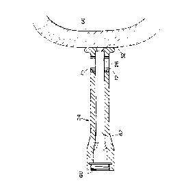
A handpiece for use in transmyocardial revascularization heart-synchronized pulsed laser system includes a barrel (24) having a
passage (62) for transmitting a laser beam; a surface (32) at the distal end of the barrel for contacting the wall of the heart (66); an aperture
(26) located at the distal end of the barrel in the enlarged surface (32) for transmitting the laser beam; and means for focusing (42) the
laser beam proximate to the aperture to vaporize the tissue of the heart wall and create a hole to the interior heart chamber.


French Abstract

Une pièce à main utilisée dans un système lase pulsé synchronisé par rapport au coeur de revascularisation transmyocardique comprend un cylindre (24) pourvu d'un passage (62) destiné à transmettre un faisceau laser; une surface (32) située à l'extrémité distale du cylindre et destinée à entrer en contact avec la paroi du coeur (66); une ouverture (26), située au niveau de l'extrémité distale du cylindre dans la surface élargie (32) et permettant de transmettre le faisceau laser; et des moyens de focalisation (42) le faisceau laser à proximité de l'ouverture afin de vaporiser les tissus de la paroi du coeur et de pratiquer un trou pour accéder à l'intérieur de la cavité cardiaque.

Claims

Note: Claims are shown in the official language in which they were submitted.


THE EMBODIMENTS OF THE INVENTION IN WHICH AN EXCLUSIVE PROPERTY
OR PRIVILEGE IS CLAIMED ARE DEFINED AS FOLLOWS:
1. A handpiece for use in a transmyocardial
revascularization heart synchronized pulsed laser system
comprising:
a barrel having a passage for transmitting a laser
beam; and
a generally transverse contacting wall at one end
of said barrel, said wall including an aperture smaller in
diameter than, and in communication with, said passage and a
face extending continuously radially outward from said aperture
to the periphery of said contacting wall.
2. The handpiece of claim 1 further including means
for focusing a laser beam transmitted through said passage to
focus the laser beam proximate said aperture to vaporize the
tissue of the heart wall and create a hole therein.
3. The handpiece of claim 2 in which said means for
focusing focuses the laser beam beyond said contacting wall.
4. The handpiece of claim 2 in which said means for
focusing focuses the laser beam within said barrel.
5. The handpiece of claim 2 in which said means for
focusing focuses the laser beam in said aperture.
6. The handpiece of claim 1 in which said contacting
wall is broader in cross-sectional area than said barrel and
said contacting wall is smooth and flat with all the edges
rounded.
7. The handpiece of claim 1 further including means
for introducing a gas to purge said passage of debris from the
vaporized heart wall.
8. The handpiece of claim 7 further including exhaust
means in communication with said passage for venting debris
purged by the gas.
9. The handpiece of claim 8 in which said exhaust
means is located proximate said aperture.
10. The handpiece of claim 1 in which said barrel is
straight.
11. The handpiece of claim 1 in which said contacting
wall is thermally insulating.

12. The handpiece of claim 1 in which said barrel is
angled and includes deflecting means for directing a laser beam
along the angled barrel.
13. The handpiece of claim 12 in which said deflecting
means includes a mirror.
14. A handpiece for use in a transmyocardial
revascularization heart synchronized pulsed laser system
comprising:
a barrel having a passage for transmitting a laser
beam;
a generally transverse contacting wall at one end of
said barrel, said wall including an aperture smaller in diameter
than, and in communication with, said passage and a face
extending continuously radially outward from said aperture to
the periphery of said contacting wall; and
means for focusing a laser beam transmitted through
said passage to focus the laser beam proximate said aperture to
vaporize the tissue of the heart wall and create a hole therein.
15. The handpiece of claim 14 in which said contacting
wall includes a solid face.
16. The handpiece of claim 14 in which said contacting
wall is smooth and flat with all the edges rounded.
17. A handpiece for use in a transmyocardial
revascularization heart synchronized pulsed laser system, the
handpiece comprising:
a barrel having an internal passage for
transmitting a laser beam; and
a contacting wall extending transversely from one
end of said barrel, said contacting wall having an aperture
smaller in diameter than, and in communication with, said
passage of said barrel, said contacting wall having a face
extending continuously radially outward from said aperture to
the periphery of said contacting wall.
18. A handpiece for use in a transmyocardial
revascularization heart synchronized pulsed laser system, the
handpiece comprising:
a barrel having an internal passage for
transmitting a laser beam; and

a generally transverse contacting wall at one end
of said barrel, said wall including an aperture smaller in
diameter than, and in communication with, said passage and a face
extending continuously radially outward from said aperture to the
periphery of said contacting wall such that the combination of
the barrel and the contacting wall acts as a handpiece for
contacting a beating heart during use of a transmyocardial
revascularization heart synchronized pulsed laser system.

Description

Note: Descriptions are shown in the official language in which they were submitted.


21 17423
HANDPIECE FOR TRANSMYOCARDIAL VASCULARIZATION
HEART-SYNCHRONIZED PULSED LASER SYSTEM
FIELD OF INVENTION
This invention relates to a handpiece for use in a
transmyocardial vascularization heart-synchronized pulsed laser
system, and more particularly to such a handpiece whose contact
surface avoids destabilization of the beating heart.
BACKGROUND OF INVENTION
Transmyocardial revascularization (TMR) is an alternative
technique to bypass surgery for increasing blood flow to the
heart muscle. It involves the puncturing of the heart wall with
a laser to form a plurality of holes which heal on the outside
but remain open on the inside of the heart, to provide an
alternative source of blood to the heart muscle. This technique
has been employed on a stilled, by-passed heart using a COz laser
with a handpiece which rests on the heart in order to ensure
that the laser beam focus occurs at the correct point on the
heart. Recently, a dramatic improvement in TMR has enabled this
technique to be used on a beating heart without the need to slow
or still it. This has been accomplished with an innovative
synchronizing approach. However, this has introduced new
problems. A beating heart is electrically active; the contact
of a handpiece against the heart wall disrupts that electrical
activity and interferes with the heart function. Arrhythmia and
fibrillation can occur and can result in heart failure.
Further, any interference with the electrical field of the heart
interrupts the synchronous operation of the laser so that the
laser is no longer constrained to fire at the optimum moment in

;,,~ r_ 2 1 1 7 4 2 3
2
the beating heart cycle. The current handpieces used with C02
lasers have a relatively sharp tip on a gauge rod extending from
the end of the handpiece used to consistently position the
handpiece at the proper distance from the stilled heart wall for
accurate laser beam focusing and impingement. Such a tip
creates increased pressure on the heart, which can cause
arrhythmia, fibrillation, and can even puncture the wall of the
heart. Further, with these handpieces it is difficult to
maintain the laser beam perpendicular with the wall of a beating
heart as is necessary to effect clean, correctly placed holes in
the heart wall.
AF,Y OF INVENTION
It is therefore an object of this invention to provide an
improved laser handpiece for a heart-synchronized pulsed laser
system for transmyocardial vascularization.
It is a further object of this invention to provide such a
laser handpiece which more readily maintains perpendicularity
with the wall of a beating heart.
It is a further object of this invention to provide such a
laser handpiece which accurately locates the laser beam focal
point at the correct point on the heart wall.
It is a further object of this invention to provide such a
laser handpiece which reduces interference with the heart
electric field and function.
It is a further object of this invention to provide such a
laser handpiece which dissipates the laser plume to prevent
interference with or damage to the laser beam lens.
This invention results from the realization that an

CA 2 i 17423
WO 94/14383 PCT/US92/11002
3
effective and safe handpiece capable of contacting the wall of
a beating heart to insure proper location and focus of the
laser beam, yet minimize danger to or interference with the
beating heart can be achieved by focusing the laser beam in
the vicinity of the laser beam exit aperture at the end of the
handpiece and providing a large, smooth, flat heart contact
surface at that end of the handpiece to,minimize pressure on
an interference with the beating heart.
This invention features a handpiece for use in a
transmyocardial vascularization heart-synchronized pulsed
laser system including a barrel having a passage for
transmitting a laser beam. There is a surface at the distal
end of the barrel for contacting the wall of the heart and an
aperture located at the distal end of the barrel in the
enlarged surface for transmitting a laser beam. There are
means for focusing a laser beam proximate to the aperture to
vaporize the tissue of the heart wall to create a hole to the
interior of the heart chamber. In a preferred embodiment the
handpiece further includes means for introducing a gas to
purge the passage, between the aperture and the means for
focusing, of debris from the vaporized heart wall. There may
also be exhaust means for for venting the debris purged by the
gas. The barrel may be straight or may be angled and include
deflecting means for redirecting the laser beam along the
angled barrel. The deflecting means may include a mirror.
The contact surface at the distal end of the barrel is
generally smooth and flat with rounded edges, and is generally
greater than i.cm in diameter. The gas may be introduced
proximate the means for focusing and exhausted proximate the
aperture. The beam may be focused beyond the enlarged
surface, within the barrel or intermediately within the
aperture.
DISCLOSURE OF PREFERRED EMBODIMENT
Other objects, features and advantages will occur to
those skilled in the art from the following description of a
preferred embodiment and the accompanying drawings, in which:
et tQeTt-n rr~ eueeT

~A2i17423
WO 94/14383 PCT/US92111002
4
Fig. 1 is a three-dimensional view of a COZ surgical laser
system employing the handpiece of this invention;
Fig. 2 is an en~arged view of a handpiece according to
this invention and a portion of the articulated optical arm
which carries it;
Fig. 3 is an enlarged cross-sectional view of the
focusing lens section of the handpiece of Figs. 1 and 2;
Fig. 4 is an enlarged sectional view of the barrel of the
handpiece of Figs. 1 and 2; and
Fig. 5 is a side elevational view with portions broken
.away of an alternative form of barrel similar to that shown in
Fig. 4.
The handpiece of this invention for use in a
transmyocardial revascularization heart-synchronized pulsed
laser system may be accomplished using a barrel having a
passage for transmitting a laser beam. The barrel may be
simply a hollow tube. There is a surface at the distal end of
the barrel for contacting the wall of the heart. This surface
is smooth and flat so that there are no sharp edges to probe
or prick the heart wall. It is also broad in order to
minimize the contact pressure between the handpiece and the
heart wall and minimize interference with the operation of the
heart muscle and the electrical activity of the beating heart.
The handpiece, at~least at its contact surface, is
electrically and thermally insulating for the same purpose.
There is an aperture located at the distal end of the barrel
in the enlarged surface for transmitting a laser beam through
to the heart wall. There are also some~means for focusing the
laser beam proximate to the aperture to vaporize the tissue of
the heart wall and create a hole through the wall to the
interior of the heart chamber. The laser may be focused at,
near or beyond the aperture. There is an inlet to introduce a
purging gas through the passage to purge, the aperture and the
means for focusing, of debris produced by the vaporization of
the heart wall by the laser beam. The means for focusing is
typically a lens which is mounted in the focusing unit or lens
unit associated with the barrel. There is one or more outlets
SUBSTITUTE SHEET

v 21 17423
proximate the distal end of the barrel through which the purged
gas with the debris is vented. The barrel may be straight or
may be angled. If it is angled there are suitable deflecting
means such as mirrors or reflectors, to redirect the beam along
the angled or curved barrel. Typically the enlarged surface for
contacting the heart is 1 cm or more in diameter.
There is shown in Fig. 1 a surgical laser system 10
including a power supply 12 and control panel 14 for operating
COZ laser 16, whose output beam is directed through an
articulated arm 18 to handpiece 20. Handpiece 20 may include a
lens unit 22 including a lens for focusing the laser beam and a
barrel 24 which includes an aperture 26 through which the laser
beam 28 exits. The distal end 30 of barrel 24 includes a
generally transverse enlarged contact wall or surface 32 for
contacting the wall of the heart to be perforated by the laser
beam. Surface 32 is relatively large to minimize the contact
pressure between it and the heart wall, and is flat and smooth
with rounded edges to minimize interference with the heart.
Surface 32 is typically 1 cm or greater in diameter, and may be
electrically and thermally insulating.
The focusing unit or lens unit 22, Fig. 3, includes a
threaded portion 38 for interconnection with arm 18, and a
threaded portion 40 which interconnects with barrel 24. Carried
within unit 22 is focusing lens 42. An inlet tube 44 is joined
by interference fit with bore 46 and a cylindrical wall 48 of
unit 22. At its free end 50, inlet 44 is connected to a hose 52
which is in turn connected to a purge gas source 54 which
provides a gas such as COZ under gentle pressure to create a
backflow from lens 42 forward into barrel 24. This keeps any
debris from the vaporization from contacting and obscuring or
damaging lens 42. Lens 42 is positioned directly in line with
passage 56 provided in unit 22 for propagation of the laser
beam. Threads 40 of lens unit 22 engage with threads 60 of
barrel 24, Fig. 4, which also includes a passage 62 which
communicates with smaller diameter laser aperture 26 to create
a clear passage for the propagation of laser beam 20a to wall 66
of a

Ca2i17423
WO 94/14383 PCT/US92/11002
6
beating heart. Lens 42 focuses the laser beam proximate
aperture 26 and surface 32.
As can be seen clearly in Fig. 4, con~act surface 32 is
considerably broader than the cross-sectional area of barrel
24 alone and is formed in the shape of a flange with surface
32 being smooth and flat and all the edges rounded. This
increases the area of contact with the heart, and therefore
decreases the pressure or force per unit area on the heart. It
also provides a more stable platform by which to maintain
perpendicularity between the beam 28 and the heart wall 66.
Thus this construction provides the necessary precision in
locating the focus of the beam on the heart wall without
interfering with the heart operation or its electrical
activity. Barrel 24 includes vent holes 70, 72 for exhausting
the purging gas and trapped debris away from the lens 42 and
away from aperture 26.
Although barrel 24 has been shown as a straight member,
this is not a necessary limitation of the invention. For
example, barrel 24a, Fig. 5, may include a right angle
configuration 80, so that surface 32a is facing at right
angles to the path of the beam 28. A reflective surface 82 is
provided to reflect the beam from an incoming path parallel to
axis 84 to the outgoing path parallel to axis 86. One or more
vent holes 88 are provided for exhausting the first gas.
Although specific features of the invention are shown in
some drawings and not others, this is for convenience only as
each feature may be combined with any or all of the other
features in accordance with the invention.
Other embodiments will occur to those skilled in the art
and are within the following claims:
What is claimed is:
t~~i mc~'rt~'t tT~ C~..ttC't"

Representative Drawing
A single figure which represents the drawing illustrating the invention.
Administrative Status

2024-08-01:As part of the Next Generation Patents (NGP) transition, the Canadian Patents Database (CPD) now contains a more detailed Event History, which replicates the Event Log of our new back-office solution.

Please note that "Inactive:" events refers to events no longer in use in our new back-office solution.

For a clearer understanding of the status of the application/patent presented on this page, the site Disclaimer , as well as the definitions for Patent , Event History , Maintenance Fee  and Payment History  should be consulted.

Event History

Description Date
Inactive: IPC expired 2016-01-01
Inactive: IPC removed 2015-12-14
Inactive: IPC deactivated 2011-07-27
Time Limit for Reversal Expired 2009-12-22
Letter Sent 2008-12-22
Inactive: IPC from MCD 2006-03-11
Inactive: First IPC derived 2006-03-11
Inactive: IPC from MCD 2006-03-11
Grant by Issuance 2000-04-18
Inactive: Cover page published 2000-04-17
Pre-grant 2000-01-20
Inactive: Final fee received 2000-01-20
Inactive: Cover page published 1999-09-28
Notice of Allowance is Issued 1999-08-12
Letter Sent 1999-08-12
Notice of Allowance is Issued 1999-08-12
Inactive: Application prosecuted on TS as of Log entry date 1999-08-10
Inactive: Status info is complete as of Log entry date 1999-08-10
Inactive: Approved for allowance (AFA) 1999-07-21
All Requirements for Examination Determined Compliant 1994-07-25
Request for Examination Requirements Determined Compliant 1994-07-25
Application Published (Open to Public Inspection) 1994-07-07

Abandonment History

There is no abandonment history.

Maintenance Fee

The last payment was received on 1999-12-01

Note : If the full payment has not been received on or before the date indicated, a further fee may be required which may be one of the following

  • the reinstatement fee;
  • the late payment fee; or
  • additional fee to reverse deemed expiry.

Please refer to the CIPO Patent Fees web page to see all current fee amounts.

Fee History

Fee Type Anniversary Year Due Date Paid Date
MF (application, 5th anniv.) - standard 05 1997-12-22 1997-09-24
MF (application, 6th anniv.) - standard 06 1998-12-22 1998-11-19
MF (application, 7th anniv.) - standard 07 1999-12-22 1999-12-01
Final fee - standard 2000-01-20
MF (patent, 8th anniv.) - standard 2000-12-22 2000-10-26
MF (patent, 9th anniv.) - standard 2001-12-24 2001-10-18
MF (patent, 10th anniv.) - standard 2002-12-23 2002-11-18
MF (patent, 11th anniv.) - standard 2003-12-22 2003-10-29
MF (patent, 12th anniv.) - standard 2004-12-22 2004-09-07
MF (patent, 13th anniv.) - standard 2005-12-22 2005-09-26
MF (patent, 14th anniv.) - standard 2006-12-22 2006-10-04
MF (patent, 15th anniv.) - standard 2007-12-24 2007-10-10
Owners on Record

Note: Records showing the ownership history in alphabetical order.

Current Owners on Record
PLC MEDICAL SYSTEMS, INC.
Past Owners on Record
ROBERT I. RUDKO
Past Owners that do not appear in the "Owners on Record" listing will appear in other documentation within the application.
Documents

To view selected files, please enter reCAPTCHA code :


To view images, click a link in the Document Description column. To download the documents, select one or more checkboxes in the first column and then click the "Download Selected in PDF format (Zip Archive)" or the "Download Selected as Single PDF" button.

List of published and non-published patent-specific documents on the CPD .

If you have any difficulty accessing content, you can call the Client Service Centre at 1-866-997-1936 or send them an e-mail at CIPO Client Service Centre.


Document
Description 
Date
(yyyy-mm-dd) 
Number of pages   Size of Image (KB) 
Drawings 1994-07-25 2 37
Description 1994-07-25 6 281
Claims 1994-07-25 2 51
Abstract 1994-07-25 1 37
Cover Page 2000-03-09 1 44
Cover Page 1995-07-29 1 31
Description 1999-07-21 6 311
Claims 1999-07-21 3 116
Cover Page 1999-09-28 1 31
Representative drawing 1998-07-21 1 12
Representative drawing 2000-03-09 1 6
Commissioner's Notice - Application Found Allowable 1999-08-12 1 163
Maintenance Fee Notice 2009-02-02 1 171
PCT 1994-07-25 4 141
Correspondence 2000-01-20 1 26
Fees 1996-10-29 1 54
Fees 1995-10-26 1 48
Fees 1994-10-25 1 54
Prosecution correspondence 1994-07-25 11 420
Prosecution correspondence 1997-11-21 7 281
Prosecution correspondence 1998-05-05 2 79
Examiner Requisition 1997-09-26 2 41
Examiner Requisition 1998-01-06 2 64
Courtesy - Office Letter 1995-12-20 1 15