Note: Descriptions are shown in the official language in which they were submitted.
~ ~ 2 1 1 7 4 6 4 ~ F~7~ l'A~ L;~ ~
A Device for Measuring a Level of Material using Microwaves
The invention relates to a level measuring device using micro-
waves comprising an antenna for sending transmitted waves
toward the surface of a material whose level is to be measured,
and for the reception of echo waves resulting from reflection
at the surface, and a receiving and evaluating circuit adapted
to derive from the echo waves received by the antenna an echo
function representative of the echo amplitudes as a function of
the distance and to determine from the echo function the tran-
sit time of the microwaves from the antenna to the surface of
the material and therefrom the distance of the surface of the
material from the antenna.
For level measurement using microwaves all those known methods
are suitable which permit the measurement of comparatively
short distances by means of reflected microwaves. The most fa-
miliar examples thereof are pulsed radar and frequency modu-
lation continuous wave radar (FMCW radar). In the case of pul-
sed radar short microwave pulses are transmitted periodically,
which are reflected from the object whose position is to be
measured and after a transit time, which is dependent on the
distance, are received again. The received signal amplitude
versus time function constitutes the echo function. Every value
of this echo function corresponds to the amplitude of an echo
due to reflection at a certain distance from the antenna. In
the case of the FMCW method a continuous microwave is trans-
mitted, which is periodically linearly frequency modulated, for
example in accordance with a saw-tooth function. The frequency
of each received echo signal hence differs in frequency from
the instantaneous frequency, which the transmitted signal has
at the time of reception, by an amount which is dependent on
the transit time of the echo signal. The difference in fre-
quency between the transmitted signal and the received signal,
which may be obtained by mixing the two signals and evaluation
2 ~ ~ 7 ~
of the Fourier spectrum of the mixed signal, accordingly corresponds to the
distance of the reflecting surface from the antenna, and the level of the frequency
characteristic corresponds to the magnitude of the echo amplitude. This Fourier
spectrum, therefore, constitutes the echo function in this case.
A particular problem in connection with level measurement using microwaves is
that a deposit of material may build up on the antenna. This danger is more
particularly to be found in the case of dusty or pulverulent material, more
especially if the antenna is moist, and furthermore in the case of sticky and
viscous materials. While microwave antennas tolerate a certain degree of fouling,
10 they cease to be operational if the deposit layer is excessive. In this case the
radar signal will be completely absorbed at the antenna so that no useful echo
may be detected. Using conventional methods it is accordingly no longer possible
to distinguish whether there is no reflector present in the beam path, whether
there is heavy attenuation in the beam path clear of the antenna (for instance in
the case of foam on the material) or whether the antenna has been blocked by the
formation of a deposit.
The object of the invention is to provide a level measuring device using
microwaves of the type noted initially, which permits the recognition of the
formation of deposits on the antenna and of further trouble conditions such as, for
20 instance, damage to or loss of the antenna.
The invention provides a level measuring device comprising an antenna for
sending transmitted waves toward the surface of a material whose level is to be
-- 2
B 23292-83
a~-~7~64
measured and for receiving echo waves resulting from reflection of the transmitted
waves at the surface, a receiving and evaluating circuit adapted to derive from the
echo waves received by the antenna the distance of the surface of the material
from the antenna, a reference reflection point situated in at least one of the
antenna and the vicinity of the antenna, and an arrangement for comparing a
section of the echo function originating from said reference reflection point with a
predetermined threshold value.
The invention also provides a level measuring device using
microwaves comprising an antenna for sending transmitted waves toward the
10 surface of a material whose level is to be measured and for receiving echo waves
resulting from reflection of the transmitted waves at the surface, a receiving and
evaluating circuit adapted to derive from the echo waves received by the antenna
an echo function representative of the echo amplitudes as a function of the
distance between the antenna and the surface of the material and to determine
from the echo function the transit time of the microwaves from the antenna to the
surface of the material and therefrom the distance of the surface of the material
from the antenna, a reference reflection point situated in at least one of the
antenna and the vicinity of the antenna, and an arrangement for comparing a
section of the echo function originating from said reference reflection point with a
20 predetermined threshold value in order to detect a condition of the antenna.
- 2a -
23292-83
CA21 1 7464
The invention is based on the recognition that the echo func-
tion section originating from reflection in the vicinity of the
antenna changes in a characteristic fashion, if the antenna
bears a deposit of material. Such reflection may more particu-
larly originate from the antenna itself if the same is for ex-
ample in the form of a horn feeder. While there is a general
tendency to achieve optimum antenna matching to avoid discon-
tinuities in impedance so that there is no troublesome local
reflection, which would swamp the wanted signal, there is in
practice nevertheless internal reflection, as for example with
a horn feeder, at the point where feed into the antenna takes
place. The reference reflection point employed in the level
measuring device of the invention is to cause reference reflec-
tion which is as distinct as possible and is readily replicated
and which in the echo function is clearly able to be distin-
guished from reflection caused by feed to the antenna. Should
such a reference reflection point not already be available,
then in accordance with a preferred form of the invention a
reference reflector is mounted at a defined distance from the
point of feed to the antenna. The threshold value, with which
the echo function section originating from the reference re-
flection point is compared, is so set that this section of the
echo function exceeds the threshold value, if no or merely a
low degree of deposit has been formed on the antenna, but that
such section is below the threshold value if the formation of
deposit on the antenna exceeds a certain degree. The signal
indicating a state above or below the threshold value will con-
sequently indicate whether the level measuring device is sat-
isfactorily operating or whether there is a malfunction thereof
owing to such deposit formation on the antenna.
Advantageous developments and features of the invention are
defined in the dependent claims.
Further features and advantages of the invention will be under-
stood from the following description of a working embodiment in
conjunction with the drawings in which:
CA2117464 4
Figure 1 shows the principle of a level measuring device oper-
ating with microwaves;
Figure 2 is a block circuit diagram of a level measuring device
having means for detection of the formation of a
deposit on the antenna and of further trouble condi-
tions;
Figure 3 shows the echo function of a conventional antenna,
when there is no deposit on the antenna;
Figure 4 shows the echo function of the same antenna as in
Figure 3 when there is a deposit;
Figure 5 shows the echo function of the an antenna fitted with
a reference reflector, when there is no deposit
formed on the antenna;
Figure 6 shows the echo function of the same antenna as in
Figure 5 when there is a deposit; and
Figure 7 shows diagrams to explain the fashion of operation of
the level measuring device in accordance with Figure
2.
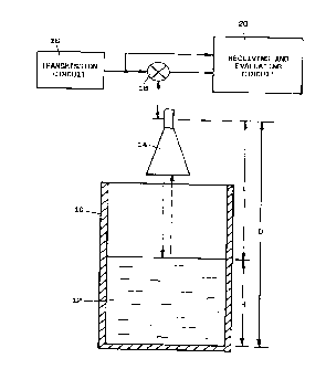
Figure 1 in the drawings shows a container 10, which is filled
up to a height or level H with a material 12. For measuring the
level H an antenna 14 is mounted above the container 10, which
transmits an electromagnetic wave toward the surface of the
material 12 and which can receive the echo wave due to reflec-
tion at the surface. The transmitted electromagnetic wave is
produced by a transmission circuit 16, which is connected via a
transmit-receive switch 18 with the antenna 14. The echo wave
received by the antenna 18 is supplied via the transmit-receive
switch 18 to a receiving and evaluating circuit 20, which on
the basis of the transmitted signal supplied by the transmis-
sion circuit 16 to the antenna 14 and the received signal sup-
CA21 1 7464
plied by the antenna 14 determines the distance E between theantenna 14 and the surface of the material 12. Since the dis-
tance D of the antenna 14 from the bottom of the container 10
is known, the difference between this distance D and the meas-
ured distance E will be the sought material level H.
Since the distances to be measured are extremely small in com-
parison with the speed of propagation of the electromagnetic
waves, very short waves must be utilized in order to attain
sufficient accuracy of measurement, which are in the microwave
range. The antenna 14 is naturally designed for the transmis-
sion and the reception of such short waves; it is for example
fitted with a horn feeder as is indicated in Figure 1.
For the measurement of the distance E any known radar method
can be employed. All such methods are based on the principle
that the transit time of the electromagnetic waves from the
antenna to the reflecting surface and back to the antenna again
is measured. Since the speed of propagation of the electromag-
netic waves is known it is possible to compute the path trav-
eled from the transit time measured. Since besides the useful
echo, which results from reflection at the surface to be de-
tected, interfering echoes may occur as well, it is conven-
tional for the entire received signal to be converted into an
echo function, which represents the intensity distribution of
the received signal as a function of the distance. From this
echo function the useful echo is determined and the transit
time thereof ascertained.
One known radar method is pulsed radar, in the case of which
short pulses are periodically transmitted and in a reception
phase following each transmission of a pulse the echo signals
at the frequency of the transmitted pulse are detected. In this
case the signal amplitude received in the course of each recep-
tion phase against time will directly constitute the echo func-
tion. Each value of this echo function corresponds to the am-
plitude of an echo due to reflection at a certain distance from
the antenna. The position of the useful echo in the echo func-
CA21 1 7464
tion will therefore directly indicate the distance to be meas-
ured.
Direct transit time measurement is avoided in the frequency
modulation continuous wave method (FMCW method). In such method
a continuous microwave is transmitted, which is periodically
linearly frequency modulated, for example in accordance with a
saw-tooth function. The frequency of each received echo signal
consequently differs in frequency from the instantaneous fre-
quency, which the transmitted signal has at the time of recep-
tion, by an amount which is dependent on the transit time of
the echo signal. The difference in frequency between the trans-
mitted signal and the received signal, which may be obtained by
mixing the two signals and evaluation of the Fourier spectrum
of the mixed signal, accordingly corresponds to the distance of
the reflecting surface from the antenna, and the level of the
frequency characteristic corresponds to the magnitude of the
echo amplitude. This Fourier spectrum, therefore, constitutes
the echo function in this case.
The antenna serves for feeding into the process, the best pos-
sible impedance match being employed in order to avoid imped-
ance discontinuities so that no interfering local reflections
occur, which would swamp the wanted signal. Nevertheless in
practice, for instance with a horn feeder, internal reflection
will occur at the point of feed into the antenna and at the
horn.
A particular problem in connection with level measurement
using microwaves is that a deposit of material may build up on
the antenna. This danger is more particularly to be found in
the case of dusty or pulverulent material, more especially if
the antenna is moist, and furthermore in the case of sticky and
viscous materials. While microwave antennas tolerate a certain
degree of fouling, they cease to be operational if the deposit
layer is excessive. In this case the radar signal will be com-
pletely absorbed at the antenna so that no useful echo may be
detected. Using conventional methods it is accordingly no
J~ 2il 7464 7
longer possible to distinguish whether there is no reflector
present in the beam path, whether there is heavy attenuation in
the beam path clear of the antenna (for instance foam on the
material) or whether the antenna has been blocked by the forma-
tion of a deposit.
Figure 2 shows a block circuit diagram of the transmission cir-
cuit and of the receiving and evaluating circuit of a level
measuring device operating in accordance with the pulsed radar
method, in the case of which additional measures have been
adopted in order to recognize the formation of deposits on the
antenna and possibly other trouble conditions.
Figure 2 again diagrammatically shows the antenna 14 in the
form of a horn feeder. A generator 24 produces a continuous
ultrahigh frequency oscillation with the frequency of the
microwaves to be transmitted, which is supplied via a beam
splitter 26 to a switch 28. The switch 28 is periodically oper-
ated by a trigger signal TR, which is produced by a trigger 30
on the basis of a clock signal CL supplied by a clock 32.
The output of the switch 28 is connected via a directional cou-
pler 34, which assumes the role of the transmit-receive switch
in Figure 1, with the feed pin 36 of the antenna 14. Each time
the switch 28 is closed a short time a short pulse is transmit-
ted from the antenna 14. The echo signals received as a conse-
quence of the transmission of pulses by the antenna are sup-
plied via the directional coupler 34 to one input of a mixer
38, which at its second input gets a signal derived from the
output signal of the generator 24 by the beam splitter 26. The
envelope signal obtained by the mixing of the two signals in
the mixer 38 is amplified in an amplifier 40 whose output is
connected with a logarithmizing circuit 42, which compensates
for the attenuation, dependent on the transit time, of the echo
signals. The logarithmized and amplified envelope signal HS de-
livered at the output of the logarithmizing circuit 42 and
which represents the echo function, is supplied to electronic
CA21 1 7464
evaluating circuitry 44, which from it determines the transit
time of the working echo and the distance E sought.
The part of the circuit in Figure 2 so far described is the
same as a conventional distance measuring device operating with
reflected electromagnetic waves as familiar to those in the
art. The diagram of Figure 3 shows the echo function repre-
sented by the envelope signal HS, of such a conventional dis-
tance measuring device in a case in which there is no deposit
formation or other trouble condition, whereas the diagram of
Figure 4 shows the corresponding echo function when there is a
substantial deposit on the antenna. The instant to corresponds
to the start of the trigger pulse supplied by the trigger 30 to
the switch 28, and which causes the closing of the switch 28.
At the instant ts the transmission pulse, produced by the
switch 28, arrives at the feed pin 36 of the antenna 14, this
causing a distinct peak in the echo function. This is followed
by echoes decreasing in amplitude which are due to reflections
occurring at the horn feeder. At the instant tE the diagram of
Figure 4 comprises a further distinct peak, which corresponds
to the reception of the useful echo.
From the diagram in Figure 4 it appears that when there is a
considerable deposit on the antenna, the form of the echo func-
tion at the antenna is altered in a characteristic fashion,
since owing to absorption by the deposit less energy will be
reflected from this part. Furthermore in the echo function of
Figure 4 the echo amplitude originating from the useful echo is
so greatly attenuated that it is now insufficient for evalua-
tion.
The recognition of deposits on the antenna 14 is in the case of
the distance measuring device in accordance with Figure 2 based
on the evaluation of the characteristic changes of the part of
the echo function, which stems from reflection at the antenna
part. This is something which is certainly possible in the case
of the echo functions with the form depicted in Figures 3 and
4. It is, however, more convenient, if a reference reflection
CA21 1 7464
point is present in the antenna part to produce a reference
echo with a distinct reflection peak. In many cases such a ref-
erence reflection point can be constituted by a part of the
antenna present in any case, for example by the edge of the
horn feeder. Should such a reference reflection point not be
present, then preferably a special reference reflector is
mounted in the antenna area. Figure 2 shows such a reference
reflector 46, which is arranged at the edge of the horn feeder
of the antenna 14 in such a manner that it projects into the
interior of the horn feeder. The reference reflector can be a
screwed on sheet metal component, a wire loop, a groove, a cor-
rugation or the like. The arrangement adjacent to the antenna
edge is advantageous in order to produce a distinct separation
between the peak due to feeding action and the peak caused by
the reference reflector in the echo function. If desired the
reference reflector may also be arranged at a small distance in
front of the antenna.
The diagrams of Figures 5 and 6 show in an analogous manner to
the diagrams of Figures 3 and 4 the echo functions of an an-
tenna fitted with such an additional reference reflector with
and, respectively, without a build up of deposit on the an-
tenna. The echo information represented in the diagram in
Figure 5 comprises the peak caused by the reference reflector
46 at the instant tR in addition to the peaks caused by the
feed at the instant tg and by the useful echo at the instant
tE. The echo function in Figure 6 shows that characteristic
changes caused by the build up of a deposit are very distinct,
in particular at the reference peak, and permit a clear dis-
tinction to be drawn between the two conditions.
For the evaluation of the characteristic changes, due to the
deposit formation, in the echo function the circuit of Figure 2
comprises control logic circuitry 50 and an amplitude compa-
rator 51, which at its first input receives the envelope signal
HS from the output of the logarithmizing device 42 and at its
second input receives a threshold value signal SWl. The am-
plitude comparator 51 is designed in a conventional manner so
CA2i 1 7464
that its output signal assumes one or the other of two signal
values dependent on whether the envelope signal HS supplied to
the first input is larger or smaller than the threshold value
SWl supplied to the second input. The amplitude comparator 51
furthermore possesses a control input, which receives an enable
signal EN1 from one output of the control logic circuitry 50.
The control logic circuitry 50 receives the clock signal CL
supplied by the clock 32 and the output signal TR supplied by
the trigger 30, such output signal determining the points in
time for transmission; on the basis of such two signals it pro-
duces the enable signal ENl so that the amplitude comparator 51
is only enabled during a certain time window after the trans-
mission of a pulse for the performance of amplitude comparison.
The function of the comparator 51 and of the control logic cir-
cuitry 50 is apparent from the diagrams in Figure 7. Such dia-
grams show the course of the envelope signals HSa and HSb,
which correspond to the echo functions of Figure 5 and, respec-
tively, Figure 6, and furthermore the clock signal CL supplied
by the clock 32, the trigger signal TR from the trigger 30 and
the enable signal EN1 supplied by the control logic circuitry
50. In the diagrams for the two envelope signals HSa and HSb
the threshold value SW1 of the comparator 51 is marked. The
control logic circuitry 50 produces the enable signal EN1 at a
time, which is exactly set by the clock signal CL, after the
start of the trigger signal TR so that the time window T1 as
set by the enable signal EN1 corresponds to that time interval
in which the reference echo, caused by the reference reflector
46, appears in the envelope signal. In this time window the
comparator 51 compares the envelope signal HS with the thresh-
old value SW1. It will be seen that envelope signal HSa corre-
sponding to the antenna without a deposit thereon in the time
window T1 exceeds the threshold value SW1 of the comparator;
the output signal of the comparator 51 hence assumes a first
signal value, as for example the low signal value, which indi-
cates that there is no interfering deposit formation on the
antenna 14. On the contrary the envelope signal HSb, corre-
sponding to the antenna with deposit formation thereon, in the
CA2117464 11
.
time window T1 will keep below the threshold value SW1 so that
the output signal of the comparator 51 will assume the second
signal value - in the example selected, the high signal value -
which indicates that there is a deposit of the antenna which
may cause the level measuring to be incorrect or even impos-
sible.
The timing and the duration of the enable signal ENl and fur-
thermore the level of the comparator threshold value SWl con-
stitute three adjustable parameters, by means of which the cir-
cuit can be adapted to suit different conditions of operation.
The selection of the timing of the enable signal permits in
particular the adaptation to different positions of the ref-
erence reflector. The duration of the enable signal is so set
that the reference echo, dependent on its form, is employed in
an optimum fashion. The level of the comparator threshold value
is selected in a manner dependent on the degree of deposit for-
mation, as from which interference with level measuring may be
expected.
The output signal from the comparator may be utilized in dif-
ferent manners. In the simplest case it can be used to indicate
the formation of a deposit or raising an alarm in order to warn
the operator who will then take the necessary action. However
it may also be employed to initiate automatic measures, which
despite the formation of a deposit will render further measur-
ing possible, as for example by increasing the transmission
power and/or by increasing the reception gain.
As shown in Figure 2, it is possible to provide further comp-
arators 52, 53,... in addition to the comparator 50, which com-
pare the envelope signal HS with different threshold values
SW2, SW3... and receive enable signals EN2, EN3 from the con-
trol logic circuitry 50, such enable signals being identical or
different. Such additional comparators render possible a finer
differentiation for monitoring of deposit formation, an indica-
tion of the current degree of fouling or the monitoring of fur-
ther causes of interference. For example a comparator whose
-~A2117464 12
tion of the current degree of fouling or the monitoring of fur-
ther causes of interference. For example a comparator whose
threshold value is set to be higher than the threshold value
SW1 indicated in Figure 7 may indicate the start of deposit
formation before the same interferes with measurements or ren-
ders them impossible. A comparator, whose threshold value is
yet below the reference echo amplitude applying for very heavy
deposit formation, may indicate complete failure of the antenna
system or of the electronic circuitry. The output signal of
this and any further comparators with different threshold
values and/or time windows can be supplied to an evaluating
logic circuitry 54, which evaluates the output signals for more
exactly determining the errors and causes of interference and
specifying the same in more detail.
The above mentioned method of recognizing formation of deposit
may be employed, in the same manner as with the pulsed radar
device described as an example, also in a frequency modulation
continuous wave radar device or in any other distance measuring
device operating with microwaves, which supplies an echo func-
tion of the above mentioned type.