Note: Descriptions are shown in the official language in which they were submitted.
CA21 1 7671
FIELD OF THE INVENTION
The invention relates to a hammermill for
fragmentation of metal car bodies and more particularly
to the individual mounting of the hammers on the ends of
the rotor arms.
BACKGROUND OF THE INVENTION
Hammermills of the type contemplated herein are
used to break up metal car bodies. These mills, also
known as shredders, are fragmentation machines, which
meet their objective by impact.
Hammermills possess impact devices that
oscillate on the ends of radially directed rotor arms and
generally include hammers, taking on a flat position when
sufficient torsion speed of the rotor is applied. A
well-known configuration features hammers suspended
between disks that are affixed to the rotor shaft.
Another configuration features a hammer supported between
adjacent rotor arms. The hammers are located on a shaft
situated parallel to the main shaft, the radial position
of this shaft runs through all of the rotor arms and
~ A 2 ~ î 7 6 7 1
hammers. The number of shafts is equal to the number of
the rotor arms to support the hammers.
The hammers are subjected to extraordinary wear
and tear and are replaced by new hammers after only a
number of days of service. After initial use, some may
be reused after having been shifted 180~. Yet, the
production period of such a hammermill is relatively
short. The free standing ends of the rotor arms in this
type of hammermill are also subject to wear. Attempts
have been made to fit the rotor arm ends with protective
caps that are also attached to the shaft that supports
the hammers. Finally, it is worth noting that the
frequent exchange of hammers and protective caps requires
the disassembly of the full length of the supporting rod.
In the hammermills disclosed and described in
U.S. Patent No. 4,313,575 and U.S. Patent No. 3,844,494
the supporting rods for the protective caps and the
supporting rod for the hammers are situated behind each
other in circumferential direction. Thus, the front
edges of the rotor arms, especially exposed to wear, are
protected by the caps. Even though these configurations
do not require the dismantling of the hammers in order to
change the protective caps, a costly supplemental
arrangement is required to secure the caps to the rotor
arms.
SUMMARY OF THE PRESENT INVENTION
One of the primary objects of this invention is
the construction of a hammermill, specifically for the
fragmentation of metal car bodies, which requires few
parts and low maintenance, yet possesses a long service
period.
The hammermill according to the present
invention is provided with U-shaped hammers which are
attached to the rotor arms and embrace the ends of the
~ 2 i 1 7671
--3--
rotor arms. This configuration first makes it possible
for the hammers to be attached in~er~n~ent of the
adjacent rotor arms or hammers, and second makes the
supplementary use of protecting caps nnn~r~qcAry because
of the U-shape of the hammers. Not only is the number of
necessary parts greatly reduced, but this configuration
avoids the wear of protecting caps and their exchange.
One of the primary advantages of mounting the
hammers at the ends of the rotor arms is that the ends of
the arms are spared all impact and are kept free of wear
in contrast with the hammers contact with the anvil.
A further advantage of the hammers according to
the present invention, depending on their wear, is that
the hammers can be exchanged or turned around
individually. This procedure eliminates the space and
effort required for the installation and deinstallation
of hammers that are supported by one common shaft.
Another advantage of the present invention is
that the hammers are pivotally mounted at the end of a
rotor arm by a supporting rod around which the hammer is
allowed to pivot.
A preferred configuration of the invention
features a supporting rod having an eccentric member
mounted on each end which is rotatable about the axis of
the supporting rod, whereby the supporting rod can be
rotated to change the position of the hammer on the rod.
This configuration allows the hammer to slide in the
longitudinal direction of the rotor axis when the
supporting rod is turned. This eccentric support of the
hammer, therefore, allows repositioning of the hammer in
the longitudinal direction of the rotor arm after a
certain period of wear. Proportionally to the
eccentricity of the position of the eccentric members on
the supporting rod, a longer service period can be
achieved for the hammer. The radial alignment can be set
CA~l 1 7671
-4-
individually for each hammer. The procedure is simple,
and the varying degrees of wear in the axial direction of
the hammermill can be dealt with. An exchange of a
hammer is not necessary until the hammer is completely
spent in the farthest radial position. Due to the
construction of the hammermill, such an exchange can be
done "locally."
Another advantage of the invention is the
ability to adjust the eccentric members to change the
radial setting of the hammers which make it possible to
adjust the gap separation between the fly circle of the
hammers and the impact receptacle onto the material to be
fragmented.
Preferably, the supporting rod consists of two
half rods, the eccentric members of which are positioned
to engage the shanks of the U-shaped hammers. The half
rods can then be fastened to the end of the rotor arm
with screws, which are inserted from the side through the
shank of the hammer. To prevent the supporting rods from
turning, they preferably are connected to the end of the
rotor arm by adjusting springs.
The supporting rod can be fastened in at least
two positions with respect to the rotor arm. If more
than two positions are desired, more adjusting spring
connections will facilitate this change. Instead of an
adjusting spring connection, a multiple edge
configuration of the supporting rod can be employed which
is inserted into a corresponding opening of the rotor
arm.
The rotor arms are preferably configured as
rotor pairs, and are fastened to the main shaft in an
arrangement of 90~ adjoining each other. On the
circumference, therefore, four rows of hammers are
arranged. Instead of pairs, these can also be configured
in triplicate so that six rows of hammers are aligned on
CA21 1 7671
--5--
the circumference. The configuration of the rotor arms
on the end of the main shaft can also be arranged as a
single rotor arm. The invention has the advantage that
only as many rotor arms as are necessary as hammers are
provided.
The width of the hammers in the direction of
the axis of the main shaft corresponds to the distance
between adjacent rotor arms. However, the hammers can be
of broader width so that overlap of the track of travel
of adjoining hammers results.
Preferably, the rotor arms are fastened to the
main shaft, the diameter of which tapers, by means of
adjusting springs to prevent turning, while all rotor
arms are connected with each other in the axial direction
of the main shaft by tie rods.
Other principal features and advantages of the
invention will become apparent to those skilled in the
art upon review of the following drawings, the detailed
description and the appended claims.
20BRIEF DESCRIPTION OF THE DRAWINGS
Figure 1 is a cross section view of the
hammermill having a four arm rotor;
Figure 2 is a cross section view of a
hammermill having a six arm rotor;
25Figure 3 is a side view of the rotor assembly;
Figure 4 is a cross section view of the rotor
assembly shown in Figure 3;
Figure 5 is a cross section view showing the
two positions of the hammer mounted on the rotor;
30Figure 6 is a side view of the hammer;
Figure 7 is a view of the front or of the back
of the hammer;
Figure 8 is a cross section of the hammer,
taken on line 8-8 of Figure 7;
CA21 1 7671
Figure 9 is a view of one-half of the
supporting rod;
Figure 10 is a cross section view of the
supporting rod taken on line 10-10 of Figure 11;
Figure 11 is a view of the supporting rod;
Figure 12 is a side view of an alternate
embodiment of the supporting rod;
Figure 13 is a cross section view of the
supporting rod taken on line 13-13 of Figure 14;
Figure 14 is a view of the back of the
supporting rod of Figure 12;
Figure 15 is a view of the track of travel of a
hammer shown in the two positions of the supporting rod;
Figure 16 is a front view of a four arm rotor;
Figure 17 is a front view of a six arm rotor;
and
Figure 18 is a front view of a four arm rotor
with a one arm end rotor.
Before explaining at least one embodiment of
the invention in detail it is to be understood that the
invention is not limited in its application to the
details of construction and the arrangement of the
components set forth in the following description or
illustrated in the drawings. The invention is capable of
other embodiments or being practiced or carried out in
various ways. Also, it is to be understood that the
phraseology and terminology employed herein is for the
purpose of description and should not be regarded as
limiting.
DETAILED DESCRIPTION OF THE PREFERRED EMBODIMENTS
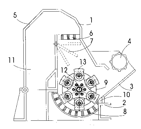
A hammermill 1 according to the present
invention is shown mounted on a housing 2. A rotor
assembly 9 is mounted on a shaft 12 located in housing 2.
The rotor assembly consists of two pairs of rotor arms to
CA2i 1 76-/1
the ends of which pivoting hammers 13 are attached.
Below the rotor assembly 9 an impact receptacle 8 is
positioned. The material to be fragmented is transported
to an anvil 10 by way of an input chute 3 and a feeding
roller 4, where it is broken down by the hammers 13. The
material to be fragmented may be car bodies, scrap iron
or even rock. The fragmented material is passed on
through the impact receptacle 8 or through a grate 6,
fitted with a flap 7, via the feed head 5 into the exit
passage 11.
A hammermill 1 of the same basic design is
shown in Figure 2 which includes a six arm rotary
assembly 9a.
A side view of the rotor assembly 9 is shown in
Figure 3 which includes a shaft 12 having seven pairs of
rotor arms 20, while vertical therewith the upper sides
of three additional arms are to be noted. The rotor
assembly 9 is constrained on each end by end plates 14,
15.
The radially protruding ends of the rotor arms
20 are equipped with U-shaped hammers 13 and 17, which
are single-jointedly connected to the rotor arms. The
hammers have recesses or grooves 16 and 18 on their outer
surfaces which are aligned in the circumferential
direction of the rotor, and which serve to improve the
fragmentation result.
Referring to Figure 4 a cross section of the
rotor assembly 9 is shown which includes a main shaft 12
having seven rotor assemblies 9 mounted thereon.
RP~PCCPC 27 are provided at spaced intervals along the
length of the shaft 12. Corresponding recesses 28 are
provided in the rotor arms 9. Springs are provided in
the recesses 27 and 28 to connect the rotor arms to the
rotor. The shaft 12 is connected to the motor by an
adjusting spring connection 19. All of the rotor arms 20
CA21 1 7671
--8--
and end plates 14 and 15 are connected by one or more tie
rods 21 that are distributed over the circumference of
the shaft.
As shown in Figures 5, 6, 7 and 8, at the end
of each rotor arm 20 a U-shaped hammer 13 is attached
that encloses the end of the rotor arm 20. The hammers
13 are secured to the rotor arms 20 by means of eccentric
rods 24 and 25 which support the hammer 13 and thus allow
the hammer to move at the end of the rotor arm. The rods
24 and 25 are fastened to both sides of the rotor arm by
a screw bolt 22 and a nut 23. An adjusting spring 26
keeps the eccentric rods from turning against themselves
in the rotor arm.
Figure 5 shows a hammer 13 mounted on the end
of a partial rotor arm 20. To demonstrate the possible
adjustment of the hammer, on the left side "I" a hammer
is shown in a position with the smallest travel radius.
On the right side "II" a hammer is shown in position with
the largest travel radius.
The hammer 13 includes two U-shaped shan~s 29
and 30 that enclose the sides of the rotor arm 20. The
shanks 29 and 30 serve to secure the hammer on the rotor
arm and simultaneously protect the end of the rotor arm.
The eccentric rods 24 and 25 are fastened in the bore
hole 31 at the end of each rotor arm by the screw 22 and
the nut 23. The eccentric rod assembly consists of two
half-axles 24 and 25, which exhibit suitable gradations
at their opposing inner surfaces so that a small gap
results between the half-axles 24 and 25 when the
half-axles 24 and 25 are fastened at the end of the rotor
arm. To prevent turning, an adjusting spring 26 is
connected between the rotor arm end and the two
half-axles 24 and 25.
The axes of the outer cylindrical members 24a
and 25a rotate eccentrically to the axes of the
C~2 i l 7671
g
half-axles 24 and 25. The cylindrical members 24a and
25a are positioned in the bore holes 31 in the shanks of
the hammer. As shown on the left side of Figure 5, the
positioning of the cylindrical member 25a results in a
travel circle at the outer end of the hammer 13 that is
smaller than the travel circle of the outer end of the
hammer 13, if the cylindrical members 24a and 25a are
positioned as shown on the right side of Figure 5.
Depending on how the half-axles 24 and 25 are turned in
the bore hole 31 of the rotor 20, a different travel
circle radius of the outer end of the hammer 13 results.
As opposed to the rotor arm 20, the half-axles 24 and 25
as shown in Figure 1, feature several adjusting spring
turn positions 33a, 33b, 33c and 33d which allow for a
corresponding number of positions of the hammer at the
end of the rotor arm.
In practical application, generally two
positions of the half-axles 24 and 25 are employed,
namely a starting position with the smallest travel
circle radius of the hammer, as shown on the right side
of Figure 5, so that the initial travel circle radius, as
shown on the left side of Figure 5, can again be
attained.
As shown in Figure 5 the screw bolt and nut 22
and 23 are protected in that the screw head and/or the
nut, respectively, are located in recesses 36 in the
half-axles 24. Referring to Figures 6, 7 and 8, a
U-shaped hammer 13 is shown which includes a head 14 and
a pair of shanks 29 and 30. A groove 16 is provided on
the upper surface of the head 14. The hammer 13 is
identical, front and back, and includes a bore hole 31 in
the shanks 29 and 30.
Referring to Figures 9, 10 and 11, one of the
eccentric members 24 is shown which shows that the axes
of the cylindrical members of the half-axle 24 have a
CA21 1 7671
--10--
greater circumferential travel eccentrically to the axis
of the inner area of the half-axle 24 which has a smaller
circumference. The recesses 3Z shown in the perimeter of
the half-axle serve as an adjusting spring notch to
secure the half-axle 24 in the rotor arm end.
The half-axle 24 as shown in Figure 11 is
located in an eccentric relation to the outer
circumference 34. The illustration shows four adjusting
spring recesses 32 staggered at 90~, thus allowing a
setting of the half-axle 24 which renders possible two
different travel circle radii of the hammer.
An alternative configuration of the eccentric
member 37 is shown in Figures 12, 13 and 14. The surface
of the half-axle 38 features an octagon configuration, as
shown in Figure 14. Figure 13 shows the corresponding
cross section of the bore hole 39 and the recess 40.
This configuration allows, with corr~cp~n~;ng forming of
the bore hole 31 in the end of the rotor arm, the setting
for four travel circle radii, whereby no adjusting
springs are needed to prevent the half-axle 37 from
turning opposite to the end of the rotor arm. The
fastening of the rotor arm end is accomplished by a screw
connection through the bore hole 39.
Figure 15 is a side view of a rotor arm 20
having a hammer 13 mounted thereon. The radius of the
two travel circles differs by the setting height 41. An
initial setting that attains the inner travel circle
radius can, after a certain amount of hammer surface
wear, be reattained by radial repositioning of the hammer
13 at the rotor arm end by turning the half-axle 24 upon
loosening the screw connection 23. This increases the
service period and heightens productivity.
An end view of a rotor assembly 9 is shown in
Figure 16 which includes a shaft 12 to which rotor arm
pairs 42 and 43 are attached. The rotor arm ends carry
~A2i 1 ~
--11--
hammers 13 and 44-46. Four tie rods 21 connect all rotor
arm pairs positioned adjacently.
An alternative hammer assembly is shown in
Figure 17 which includes a rotor having three rotor arms
47 and 48 that carry a hammer 13 at the end of each rotor
arm. At the same rotating speed of the rotor, a 50%
increase in impact count is thereby achieved.
Figure 18 shows a rotor configuration where the
end rotor arm 49 is the only arm.
There exists the option that the width of the
hammers, which generally corresponds to the sequential
distance between two successive rotor arms on the shaft,
can be selected to be larger in order to achieve overlap
of the impact area of successive hammer blows, whereby
the fragmentation result for certain material can be
increased.
If the adjustability of the hammers is not
desired, there is no need to use adjustable supporting
rods. In this case, the hammers can be linked directly
with the ends of the rotor arms by means of a single pin
connection. The U-shape or clasplike configuration of
the hammers can further be improved by the curved shape
of the base of the hammer that faces the rotor arm end in
order to afford additional protection to the rotor arm
end in the circumferential direction of the rotor. Even
though the pivotability of the hammer is thereby limited,
in practical application this is of little importance
since, based on the high count of rotor revolutions when
impacting the material to be fragmented, generally only a
slight deflection of the hammer takes place.
The number of rotor arms on the shaft can vary.
Since individual hammers are attached to the rotor arm
ends, hammermills can be constructed featuring greater
lengths than conventional hammermills where group
CA21 1 7611
-12-
attachment of all hammers along a single shaft leads to
operational difficulties.
In addition to the use of adjusting spring
links or multiple cornered connections to prevent the
half-axles from turning, any other state of the art
securing device is suitable.
Thus, it should be apparent that there has been
provided in accordance with the present invention a
hammermill that fully satisfies the objectives and
advantages set forth above. Although the invention has
been described in conjunction with specific embodiments
thereof, it is evident that many alternatives,
modifications and variations will be apparent to those
skilled in the art. Accordingly, it is intended to
embrace all such alternatives, modifications and
variations that fall within the spirit and broad scope of
the ~ppP~P~ claims.