Language selection

Search

Patent 2117946 Summary

Third-party information liability

Some of the information on this Web page has been provided by external sources. The Government of Canada is not responsible for the accuracy, reliability or currency of the information supplied by external sources. Users wishing to rely upon this information should consult directly with the source of the information. Content provided by external sources is not subject to official languages, privacy and accessibility requirements.

Claims and Abstract availability

Any discrepancies in the text and image of the Claims and Abstract are due to differing posting times. Text of the Claims and Abstract are posted:

  • At the time the application is open to public inspection;
  • At the time of issue of the patent (grant).
(12) Patent: (11) CA 2117946
(54) English Title: SAFETY MECHANISM
(54) French Title: DISPOSITIF DE SECURITE
Status: Term Expired - Post Grant Beyond Limit
Bibliographic Data
(51) International Patent Classification (IPC):
  • B66D 05/02 (2006.01)
  • B66D 01/06 (2006.01)
  • B66D 05/34 (2006.01)
(72) Inventors :
  • JUSSILA, OLAVI (Finland)
(73) Owners :
  • KCI KONECRANES INTERNATIONAL CORPORATION
(71) Applicants :
  • KCI KONECRANES INTERNATIONAL CORPORATION (Finland)
(74) Agent: G. RONALD BELL & ASSOCIATES
(74) Associate agent:
(45) Issued: 2001-02-20
(22) Filed Date: 1994-10-12
(41) Open to Public Inspection: 1995-04-16
Examination requested: 1997-10-31
Availability of licence: N/A
Dedicated to the Public: N/A
(25) Language of filing: English

Patent Cooperation Treaty (PCT): No

(30) Application Priority Data:
Application No. Country/Territory Date
08/136,370 (United States of America) 1993-10-15

Abstracts

English Abstract

A safety means for preventing a cable drum to rotate with overspeed has parallel ratchet wheels which encircle a brake drum. At a periphery of the ratchet wheels are stopping slots wherein latching means are inserted when an overspeed is detected. The slots of the adjacent ratchet wheels are staggered. Thus the braking effect of each ratchet wheel starts at a different point of time.


French Abstract

Moyen de sécurité permettant d'empêcher un enrouleur de câble de tourner en survitesse, comprenant des roues à crochet parallèles qui encerclent un tambour de frein. Au niveau d'une périphérie des roues à crochet se trouvent des fentes d'arrêt dans lesquelles des moyens de verrouillage sont insérés lorsqu'une survitesse est détectée. Les fentes des roues à crochet adjacentes sont en quinconces. Ainsi, l'effet de freinage de chaque roue à crochet commence à un point différent dans le temps.

Claims

Note: Claims are shown in the official language in which they were submitted.

6
CLAIMS
1. A safety mechanism for a crane to prevent a cable drum
operated hoist from operating above a predetermined cable
speed limit, comprising:
(a) a brake drum directly connected to the cable drum of the
hoist, the brake drum being rotatable with the cable drum in
a rotation direction;
(b) at least two ratchet wheels surrounding said brake drum
and being substantially parallel in the axial direction of
said brake drum;
(c) each of said ratchet wheels being lined with a brake
lining interposed between the ratchet wheel and said brake
drum, said ratchet wheels being fixed to and rotatable with
said brake drum by the frictional force exerted by said
brake linings on said brake drum;
(d) at least one stopping slot being provided at a periphery
of each of said ratchet wheels, at least one of said stopping
slots on one of the rachet wheels being located forwardly
in the rotation direction of the drum compared to at
least one other stopping slot on another of the ratchet
wheels; and
(e) latching means insertable into at least one of said
stopping slots for preventing rotation of the brake drum
when said predetermined cable speed limit is exceeded.
2. The safety mechanism as claimed in claim 1, wherein at
least one of said ratchet wheels is comprised of one substantially
circular part with a screw extending between ends of
the substantially circular part, the screw holding the at
least one ratchet wheel on said brake drum.
3. The safety mechanism as claimed in claim 1, wherein said
latching means is inserted simultaneously into stopping slots
of all said ratchet wheels.
4. The safety mechanism as claimed in claim 1, further comprising
an electric trigger operatively connected to the latching

7
means, the latching means being actuated by the electric
trigger.
5. The safety mechanism as claimed in claim 1, wherein the
drum brake comprises identical ratchet wheels, the ratchet
wheels forming a modular structure.
6. The safety mechanism as claimed in claim 1, wherein a
phase difference between the ratchet wheels is adjustable.
7. The safety mechanism as claimed in claim 1, wherein a
plurality of stopping slots are provided on each of the
ratchet wheels and wherein each stopping slot on one ratchet
wheel is adjacent another stopping slot on an adjacent ratchet
wheel.
8. The safety mechanism as claimed in claim 7, wherein three
ratchet wheels are provided, each of the ratchet wheels having
a plurality of stopping slots, a middle ratchet wheel being
located between the other two outer ratchet wheels, each of
the ratchet wheels having corresponding stopping slot with
corresponding stopping slots being adjacent to one another,
each stopping slot on the middy ratchet wheel being located
between corresponding stopping slots in the rotation direction
of the two outer ratchet wheels, the corresponding stopping
slots being staggered in the rotation direction.
9. The safety mechanism as claimed in claim 1, wherein three
ratchet wheels are provided, each of the ratchet wheels having
a plurality of stopping slots, a middle ratchet wheel being
located between the other two outer ratchet wheels, each of
the ratchet wheels having corresponding stopping slot with
corresponding stopping slots being adjacent to one another,
each stopping slot on the middle ratchet wheel being located
between corresponding stopping slots in the rotation direction
of the two outer ratchet wheels, the corresponding stopping
slots being staggered in the rotation direction.

8
10. The safety mechanism as claimed in claim 1, wherein the at
least two ratchet wheels have stopping slots adjacent to one
another, the adjacent stopping slots being staggered in the
rotation direction.
11. The safety mechanism as claimed in claim 1, wherein each
of the ratchet wheels have a generally circular shape with two
ends connected by a screw, each of the screws being adjustable
to vary tension at which the ratchets are held on the brake
drum.
12. The safety mechanism as claimed in claim 1, wherein each
of the at least one stopping slots have a tooth which is
engagable by the latching means, each of the slots having a
forward and rearward end relative to the rotation direction
and the teeth being located at the rearward end of the slots.

Description

Note: Descriptions are shown in the official language in which they were submitted.


2117946
-.
1
SAFETY MECHANISM
BACKGROUND OF THE INVENTION
1. Field of the invention
The present invention is directed to a safety mechanism for a
hoist having a lowering speed limit. The safety mechanism is
activated as the speed of the load exceeds the lowering limit
by a latch which locks the ratchet wheel which is rotating
with the cable drum of the hoist. The ratchet wheel has a
brake lining against the cable drum.
2. DeSCription of the Background Art
US patent 4,520,998 shows a safety mechanism as described
above. In this system, the drum is braked with a very high
braking force in the beginning of the stopping because the
brake linings may get stuck in the drum before the safety
mechanism is activated. Therefore the detaching force may have
a very high value before the brake lining of the ratchet wheel
begins to slide on the surface of the drum. The ropes may also
be weakened during over time and therefore it is possible that
the ropes may be broken when the braking force i~ very high.
The ropes should bear a force that is needed to decelerate a
maximum load from a certain speed within a predetermined
distance. The braking moment should not exceed this force in
any situation.
SUMMARY OF THE INVENTION
It is an object of this invention to produce a safety mecha-
nism for a hoist which is activated when the lowering, speed
exceeds a predetermined limit and which will act reliably in
all circumstances and will cause only limited braking force
also in the beginning of the braking. The force will be essen-
tially constant during the braking period. This problem is
solved by the present invention in that the safety mechanism
comprises at least two ratchet wheels surrounding a brake drum
and being parallel in the axial direction of brake drum. The
safety mechanism is hereinafter called also as a drum brake in

211946
2
this specification. Each of said ratchet wheels are lined with
a brake lining interposed between a ratchet wheel and said
drum. The ratchet wheels are fixed to and rotatable with said
brake drum by the frictional force exerted by said brake
linings on said brake drum. In order to activate the brake,
each of said ratchet wheels are provided at its periphery with
at least one stopping slot and at least one of said stopping
slots are transferred in the rotation direction of the drum
compared to at least one other stopping slot. When activating
the drum brake, a latching means is inserted into at least one
of said stopping slots thus preventing rotation of the brake
drum when said predetermined cable speed limit is exceeded.
In another development of the present invention, each ratchet
wheel is comprised of one circular part which is forced on
said drum by a screw connecting the ends of said part.
In one further development of the present invention, the lat-
ehing means is inserted simultaneously to stopping slots of
all said ratchet wheels.
In yet another modification of the present invention, the
latching means is actuated by an electric trigger.
According to one further modification of the invention, the
drum brake comprises identical ratchet wheels and the ratchet
wheels are forming a modular structure.
In one modification of the invention, the phase difference be-
tween the ratchet wheels is adjustable.
BRIEF DESCRIPTION OF THE DRAWING
The present invention will become more fully understood from
the detailed description given hereinbelow and the accompa-
nying drawings which are given by way of illustration only,
and thus, are not limitative of the present invention and
whereins

2117946
3
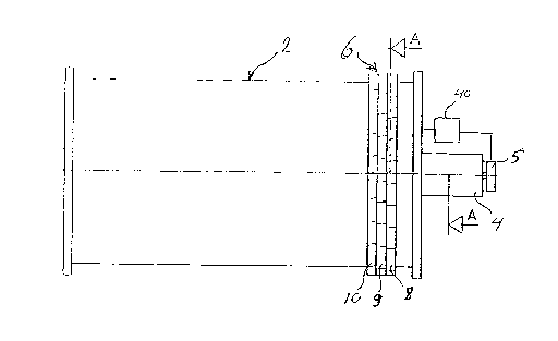
FIG.1 is a side view of the cable drum wherein the invention
is used;
FIG. 2 is a crass sectional view of the safety mechanism of
the present invention taken along lines A-A of FIG. 1; and
FIG. 3 is a cross sectional view taken along line B-B of FIG.
2.
DETAILED DESCRIPTION OF THE PREFERRED EMBODIMENTS
Figure 1 illustrates a side view of a cable drum 2 of a hois-
ting device. The cable drum is supported rotatable on its axis
4. At the other end of the cable drum 2 is arranged a drum
brake 6 of the present invention. The drum brake 6 is activa-
ted to stop the cable drum 2 when the speed of the cable drum
and thus the speed of the load hanging on the rope of the
hoisting device exceeds a predetermined speed limit. In prat-
tice the speed limit of the peripheral velocity of the cable
drum is 15-40 m/min.
Figure ~ illustrates a cross sectional view along lines A-A in
Figure 1. The drum brake 6 consists of three ratchet wheels 8,
9 and l0 having teeth on their outer surface. The ratchet
wheels encircle the brake drum 3, which is coaxial with the
cable drum and connected to it or is a structural part of the
cable drum. The ratchet wheels almost entirely surround the
brake drum 3. Each ratchet wheel 8, ~, 10 is open and its end
12 are connected to its other end 14 with a screw 16. Between
the screw 16 and the other end 14 of the ratchet wheel is
installed a spring 18 to provide a suitable pressing force
between the ratchet wheel 8 and the brake drum 3. Respectively
the ends of the ratchet wheels 9 and 10 are connected together
with screws. Each ratchet wheel 8, 9, 20 has teeth 20, 22 and
24 respectively on its outer cylinder surface and there are
slots between the teeth in every ratchet wheel. The ratchet
wheels are essentially similar and their teeth are divided in
a similar way but the teeth of the ratchet wheel 8 are trans-
ferred a distance 26 from the teeth of the ratchet wheel 9 arid
further the teeth of the ratchet wheel 9 are transferred a
distance 26 from the teeth of the ratchet wheel 10. The inner
N.

21~~9~6
4
surface 28 of the ratchet wheel is lined with a brake lining
30. The other side of the lining 30 is against the brake drum
3. As illustrated in Figure 3, which is a cross sectional view
along line B-B of the Figure 2, the ratchet wheels 8, 9 and 10
and their brake linings are parallel on the brake drum 2.
For triggering of the drum brake, a trigger mechanism 32 is
arranged near the teeth of the ratchet wheels 8, 9, 7Ø The
trigger mechanism 32 comprises a body part 34, a trigger
member 36 installed movably therein and a spring 38. The
trigger member 36 is kept by an electromagnet 37 in its inac-
tivated position as shown in the Figure 2. When the speed of
the cable drum exceeds a predetermined speed limit which is
detected e.g. by a tachometer 5 arranged on the axis 4 of the
cable drum, the electromagnet 37 is released by a control unit
40 with a signal via a conductor 42 and the trigger member 36
is moved towards the ratchet wheels by the spring 38 and into
the slots between teeth thus causing the stopping of the
ratchet wheels. In the embodiment of Figure 2 the ratchet
wheel 10 will be stopped first and its brake lining begins to
brake with a moment defined by the spring 18 of the ratchet
wheel 10. At the triggering moment the braking moment will be
a little greater because of the fact that the static moment is
greater than the dynamic friction moment. After a delay the
second ratchet wheel 9 will be locked and further after anot-
her delay the ratchet wheel 8 will be locked thus causing an
increase of the braking moment when the braking surface inc-
reases. The delay depends on the phase difference of the
ratchet wheels and the speed of the cable drum. The parts of
the hoisting equipment, like the hoisting ropes, are dimensio-
ned to bear a force which effects when a nominal load is dece-
lerated from the said speed limit in a certain time. As this
safety means is to fulfill this deceleration requirement the
starting moment in the beginning of the braking will be always
lower than the dimensioned moment because only a part of the
braking moment is used in the beginning. However, the full
moment will be reached almost immediately after triggering the
brake. In a normal case the static, i.e, detaching moment is
about 30-40% greater than the dynamic moment which is defined
::, , '':
'.. .
t. ° ' : ;

~~r<
217946
by the spring 10. The brake may be unused for a long time,
even for years, and then the static moment can be much higher,
even 70-120% greater than the dynamic moment because of corro-
sion or other age depending factors.
5 In a very advantageous embodiment of the invention, identical
ratchet wheels are used forming a modular structure. The
number of ratchet wheels is defined case by case according to
the required braking moment.
The ratchet wheels can also differ from each other in their
width and braking surface. Also, the springs of the ratchet
wheels can be different and the phase difference between the
parallel ratchet wheels may be adjustable. The number of the
ratchet wheels and their structure may have several alternati-
ves within the scope of the present invention.
The triggering mechanism can be actuated electrically or
mechanically or other different ways depending on the speed of
the cable drum or lifting rope. The embodiments of the inven-
tion may also differ from the above in other respects and the
full scope is defined by the following claims.

Representative Drawing
A single figure which represents the drawing illustrating the invention.
Administrative Status

2024-08-01:As part of the Next Generation Patents (NGP) transition, the Canadian Patents Database (CPD) now contains a more detailed Event History, which replicates the Event Log of our new back-office solution.

Please note that "Inactive:" events refers to events no longer in use in our new back-office solution.

For a clearer understanding of the status of the application/patent presented on this page, the site Disclaimer , as well as the definitions for Patent , Event History , Maintenance Fee  and Payment History  should be consulted.

Event History

Description Date
Inactive: Expired (new Act pat) 2014-10-12
Inactive: Office letter 2010-02-26
Inactive: Office letter 2010-02-24
Inactive: Reversal of will be deemed expired status 2009-12-04
Inactive: Payment - Insufficient fee 2009-12-04
Letter Sent 2009-10-13
Inactive: IPC from MCD 2006-03-11
Grant by Issuance 2001-02-20
Inactive: Cover page published 2001-02-19
Pre-grant 2000-11-29
Inactive: Final fee received 2000-11-29
Notice of Allowance is Issued 2000-06-07
Letter Sent 2000-06-07
Notice of Allowance is Issued 2000-06-07
Inactive: Approved for allowance (AFA) 2000-05-18
Inactive: Application prosecuted on TS as of Log entry date 1998-02-06
Inactive: RFE acknowledged - Prior art enquiry 1998-02-06
Inactive: Status info is complete as of Log entry date 1998-02-06
All Requirements for Examination Determined Compliant 1997-10-31
Request for Examination Requirements Determined Compliant 1997-10-31
Application Published (Open to Public Inspection) 1995-04-16

Abandonment History

There is no abandonment history.

Maintenance Fee

The last payment was received on 2000-09-14

Note : If the full payment has not been received on or before the date indicated, a further fee may be required which may be one of the following

  • the reinstatement fee;
  • the late payment fee; or
  • additional fee to reverse deemed expiry.

Patent fees are adjusted on the 1st of January every year. The amounts above are the current amounts if received by December 31 of the current year.
Please refer to the CIPO Patent Fees web page to see all current fee amounts.

Owners on Record

Note: Records showing the ownership history in alphabetical order.

Current Owners on Record
KCI KONECRANES INTERNATIONAL CORPORATION
Past Owners on Record
OLAVI JUSSILA
Past Owners that do not appear in the "Owners on Record" listing will appear in other documentation within the application.
Documents

To view selected files, please enter reCAPTCHA code :


To view images, click a link in the Document Description column. To download the documents, select one or more checkboxes in the first column and then click the "Download Selected in PDF format (Zip Archive)" or the "Download Selected as Single PDF" button.

List of published and non-published patent-specific documents on the CPD .

If you have any difficulty accessing content, you can call the Client Service Centre at 1-866-997-1936 or send them an e-mail at CIPO Client Service Centre.


Document
Description 
Date
(yyyy-mm-dd) 
Number of pages   Size of Image (KB) 
Abstract 1995-06-02 1 22
Claims 1995-06-02 3 144
Drawings 1995-06-02 1 35
Description 1995-06-02 5 255
Representative drawing 2001-01-25 1 5
Representative drawing 1998-07-01 1 18
Drawings 1998-02-24 1 34
Acknowledgement of Request for Examination 1998-02-05 1 173
Commissioner's Notice - Application Found Allowable 2000-06-06 1 162
Notice of Insufficient fee payment (English) 2009-12-03 1 91
Fees 1999-09-22 1 44
Correspondence 2000-11-28 1 29
Fees 1998-09-15 1 58
Fees 1997-09-22 1 48
Fees 2000-09-13 1 48
Fees 2009-09-23 1 39
Correspondence 2009-12-03 1 24
Fees 2009-12-15 4 148
Correspondence 2010-02-23 2 33
Correspondence 2010-02-25 1 15
Fees 1996-10-03 1 58
Prosecution correspondence 1997-11-20 5 132