Note: Descriptions are shown in the official language in which they were submitted.
633 P 054 ~
~ 2~83~ :
UNIVERSAL MOLD
(Case No. 93,988)
Inventor: John W. Von Hol t
BACXGROUND C)F THE INVENTION
Injection molds for containers, lids, and the
like are typically of a ~airly complex construction,
comprising mold plates, leader pin~, bushings, a hot
runner system, an e~ection system, a watar and/or air
cooling system, an opening and ~losing mechani~m, and
often a mold outrigger support system. Furthermore, such
molds generally must be specifi~ally manufactured to fit
the desired molding press. Molding machines or pres~es
come in various sizes and capacities, ranging typically
from 200 tons to 700 tons.
Conventional ~olds m~y have a runner plate,
which is a plate that typically holds a mold cavi~y on
one side thereof, or a pair of mold cavities on opposed
sides, and which has conduits that supply molten molding
compound to th~ re~pective sprues of th~ mold cavities.
Runner plates may be supported by outriggers, extending
fro~ corner~ of a rectangular runner plate in prior art
designs in a direction parallel to a rectangular sid~
thereof and integrally attached thereto. These
outrigger~ are proportioned to res~ upon tie bars of a
particular moldin~ press. In ~he prior art, the
, ~ .
~ 2~1~369
outriggers must be of a particular design to engage the
particular tie bars of the desired molding press, since
various molding presses of differing capacities and
manufacture have tie bars of different spacing and size.
Thus, it is typically impractical to switch a
mold from operation in one molding press to another
molding press of different design, for example a molding
press of larger capacity. In the prior art, the
outriggers of the runner plate are likely to fail to
engage the differently spaced tie bars of another design
or size of molding press.
Furthermore, in the prior art molds where the
runner plate carries a pair of mold cavities in back-to-
back relation, it is conventional for leader pins to be
present ~or lateral bracing of the mold as it opens and
closes. Typically, one set of leader pins extends from
ona of the mold cores, secured in stationary manner on
a mold core plate, which, in turn, is secured to a platen
of the mold press. The leader pins from this first mold
core plate extend outwardly through a peripheral aperture
in the runner plate, being long enough to continue
engaging the runner plate in the mold-open position, but
not significantly longer than that. Then, the other mold
core, on the other side o~ the runner plate and which
engages the corresponding mold cavity on the other side
of the runner plate, carries another set of leader pins
- 2 -
3 ~ ~
through its mold core plate which are long enough to
extend through apertures in the periphery of the runner
plate as the entire structure is moved between open and
closed positions~ but likewise not significantly longer.
Thus, when such a prior art mold is in its open
position, the leader pins are near their maximum position
of extension, where only essentially the tips of the
le~der pins occupy the apertures in the runner plate.
They would disengage from the runner plate i~ the mold
were open much further, but the mold is designed not to
open further. However, there is a weakness of lateral
stability created by this structure, that has in the
prior art been dealt with by the use of the outriggers
described above ~or added lat~ral stability.
In accordance with this invention, a mold is
provided having improved lateral stability, with the mold
also exhibiting a universal characteristic of use, i~
that the very same mold may be run in a variety of
molding presses. For example, preferred molds may be run
in a variety o~ molding presses which range in capacity
from 150 tons to 700 tonsO This provides a significant
and novel advantage, in that, in the prior art, it has
typically be~n necessary to rebuild a mold with
redesigned outriggers in order to switch its use from one
press of one capacity or design to another press of a
different capacity or design.
, .,~
3 ~ 9
~'.
.
Further in accordance with this lnvention, one
embodiment permits the elimination of the outrigger
supports altogether, if that is desired.
Thus, a great improvement is provided with the
mold of this invention.
DESCRIPTION OF THE INVENTION
In this invention, an injection mold is
provided having a runner plate which comprises: a plate
having a plurality of corners, apertures extending
through the runner plate or receiving leader pins of the
molding system for support of the plate. At least a pair
of outrigger supports are provided, the outrigger
supports being carried by the plate, each at a different
edge portion of the plate and extending diagonally
outwardly relative to adjacent plate edges. Because of
the diagonal extension of the outrigger supports, they
are capable of engagement with a variety of tie bars of
dif~erently sized mold presses, to facilitate the
mounting of a mold having a runner plate in accordance
with this ~nv~ntion in mold presses of different size or
design.
Preferably, each ou~rigger support carries a
roller which i~ positioned to engage the tie bars of the
mold press in rolling contact th~rewith ~or support of
-- 4
'''~
2~83~
.~. ,,
the mold. Thus, sliding friction is greatly reduced in
the mold operation.
Furthermore, the outrigger supports ara
adjustably positionable, as well as removable from, the
runner plate, typically so that the same outrigger
supports may be applied to the runner plate in a
different position. For example, this permits the runner
plate to be placed on the tie bars of a mold press with
the long, transverse dimension o~ the runner plate being
vertical, or, alternatively, with the long, transverse
dimension of the runner plate being horizontal. This is
typically accomplished by removing and replacing the
outrigger supports at respective corners of the runner
plate to permit this.
Specifically, each outrigger support carries
a sliding projection, for example of T-shape, while at
least three corners of the runner plate defines slots
proportioned to receive and retain sliding projeotions
of the outrigger supports. Thus, the pair of outrigger
supports may be changed in their position on the runner
plate between the respective corners, to permit changing
o~ the runner pla~e position relative to the molding
system b~tween vertical and horizontal, for example.
Also, the sliding projections may have a range of
different positions in the runner plate slots so that the
outrigger supports may be adjusted to engage dif~erently~
21.~83~
...
positioned tie bars of different mold presses. Means
such as ~et screws may ~e used to hold the outrigger
supports in their desired positions in the runner plate
slots.
The runner plates may be broadly rectanqular
in shape, but typically carrying a pair of opposed side
projections which define apertures carried adjacent the
longest edges of the plate. The apertures of the side
projections may receive the leader pins, which slide
relative to the runner plate as the mold opens and
closes. The side projections may typically be 18 to 30
inches in length along the longest edges, but less than
the length of the longest edges of the runner plate.
Specifically, a runner plate in accordance with this
invention may have a length of 28 to 40 inches and a
width of 14 to 28 inches, which dimensions accommodate
a substantial variety of mold pressesO A mold made in
accordance with this invention may be interchangeably
used in many o~ such presses.
Also, the molding system of this invention may
comprise a pair o~ mold cavities carried on opposite
sides of the runner plate, plus a pair of mold cores,
each being po~itioned to engage one of the mold ravities
in molding relation. Means are provided for moving the
molding system between a mold-closed position of engaging
mold cores and cavities, and a mold-open position, to
, ,~
2~ 1~3~9
permit removal of molded articles from the mold.
~ n accordance with this invention, the leader
pins, which are carried by at least a first of the mold
cores, extend through apertures in both of the mold
cavities and/or the runner plate. By this invention, the
leader pins are long enough to extend the entire mold
length, through the other mold core on the opposite side
of the mold, in the mold-open position, contrary to the
molds of the prior art. In other words, in the mold of
this invention/ the l~ader pins may be approximately
twice as long as in th~ prior art, extending in the mold~
open p~sition not only from one mold core through
apertures in the runner plate, but the same pins continue
onward for a distance su~ficient to extend past both o~
the mold cavities and through the other mold core, which
is positioned on the end of the mold opposite to the
first mold core. .
Typically, the leader pins are all positioned
parallel to each other, extending in the same direction
from single, stationary mold core, while the remainder
o~ th~ mold opens and closes relative to that mold cor~
However, separate pins of similar length can be
positioned to face each other if that is desired.
Becau~ie the leader pins engage and support all
the components of the mold at all times, there i~ia great
increase in the lateral stability of the mold. This
~,
21~369
.....
stability is great enough that, in the presence of such
an inventive improvement, outrigger supports ~or the
runner plate can be eliminated in many circumstances if
desired.
Pre~erably, the runner plates used in this
invention carry a plurality of slots for removable
mounting o~ at least a pair of the outrigger supports of
this invention, for supporting e~gagement of tie bars of
the molding system. ~owever, in many circumstances such
is not necessary when tha alongated leader pins in
accordance with this invention are used.
~::
DESCRIPTION OF THE DRAWINGS
In the drawings, Fig. l is a perspective view ~.
of a mold made in accordance with this invention, also
showing some part~ of a conventional mold press in which
it is mounted;
Fig~ 2 is an exploded, perspective view of an
outrigger for use with the mold of this invention;
. ,
Fig. 3 is a partial longitudinal sectional view
taken through the outrigger o~ Fig. 2, with the outrigger
shown to be mounted on the mold:
21~3~9
- 3.
;:,
Fig. 4 is a plan view of the mold of Fig. 1,
showing the mold in closed position;
Fig. 5 is an elevational view of the mold of
Fig~ 4, shown in th~ open position;
Fig. 6 is an elevational view of the runner
pla~e of the mold shown in Figs. 1-5, the runner plate
having its outriggers mounted in a first position for
hori~ontal mounting of the mold in the mold press; and
~, .
Fig. 7 is an elevational view of the same
runner plate with the outriggers mounted in a di~ferent
position for vertical mounting o~ the mold in the mold
press.
. -
D~SCRIPTION OF SPECIFIC EMBODIMENTS
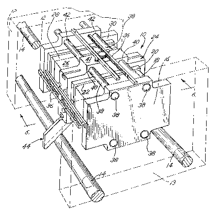
Referring to the drawings, a multiple cavity
injection mold 10 is shown in accordance with this
invention, the mold beiing mounted in a mold press in Fig.
1, with platens 12 ~ 13 and the tie bars 14 of the mc: ld
pr~ss baing shown. Tha mold 10 and mold press
illustrat~d h~rein may each be of known, commercial
design exceplt as otherwise indicated harein.
Platen 13 o~ the mold press is a stationary
2~3~9
platen, while platen 12 is movea~le by the mold press for
a desired distance betw2en open and closed mold
positions. Components of mold 10 follow along, ~overned
by rack and Pinion mechanisms 36.
Platen 13 carries a first mold core platen 16,
to which is attached the first mold core 18. First mold
cavity 20 is positioned in facing relation to mold core
18 along a parting line 22~ with ~irst mold cavity 20
being carried on one ~ace of runner plate 24, which may
be conventionally equipped with lines ~or delivering
molten plastic through the respective sprues into the
individual molding chambers 25, defined between core 18
and cavity 20 (Figs. 5-7) . Alternatively, larger molding
chambers 27 may be defined by core 18 and cavity ~0.
Runner plate 24 carries, on its other side, a
second mold cavity 26~ which engages mold core 28 . Mold
core 28 is carried on a plate 30 which, in turn, is
bolted to platen 12 of the mold press.
As shown in Fiy. 5, ~he respective mold core
units 32 and mold cavity units 34 are shown, with the
units ~ngaging each o~her to define mold chambers 25
between them, for the molding action in accordance with
::ommon practice. It can be saen that the various mold
core units 32 and mold cavi~y units 34 can vary in design
as de-~ired.
As is conventional, mold 10 i5 braced and
- 10 -
...' ...` .
controlled in its opening and closing motion by rack and
pinion connections 36, which are conventional. One or
two pairs o~ such opposed rack and pinion connections 36
may be provid~d for each mold.
In accordance with this invention, leader pins
38 are provided~ being conventionally secured in
apertures of mold core plate 16, and extending along the
entire length of mold 10, passing through apertures 40
of runner plate 24, and also through apertures 42 of
opposed mold core plate 30.
Rectangular side projections 41 are carried
integral with the otherwise rectangular runner plate 24,
with projections 41 extending along the longest edges of
the runner plate, and defining apertures 40 for receiving
the leader pins 38, which extend therethrough. The side
projections 41 may be 20 inches in length along the
longest re~tangular edges of runner plate 24, with the
longest runner plat~ edge being about 30 inches in length
and the other rectangular edges thereof being about 16
inches, by way o~ specific embodiment~
Leader pins 38 are o~ a length sufficient to
extend w011 beyond the other mold core plate 30 in the
mold-closed position, as shown in Figs. 1 and 4.
In accordance wi~h this invention, leader pins
38 are of su~ficient length, as shown in Fig. 5, to
extend beyond the opposed mold core pla~e 30 even in the
2~ ~3~ ~
mold-open position, as shown. To the contrary, in prior
art molds, the leader pins 38 are only of a length
capable of extending from the respective mold core plat~s
16, 30 to a distance that only slightly beyond runner
plate 24, so that the prior art leader pins are only
about hal~ the length of the leader pins 38 of this
invention in a correspondingly-sized mold. By this
invention, significant improvements in the lateral
stabilization of the mold is achieved, so that outrigger
supports may, if desired, be eliminated in many molding
situations.
Further in accordance with thi~ invention, mold
10 may carry at least a pair of outrigger supports 44,
one such support 44 being positioned on each side of the
mold to rest on a tie bar 14 of the mold press as shown
in Figs. 1, 6 and 7. When outrigger supports 44 are
present, leader pins of conventional length may be used
in the mold rather than these shown herein, as may be
desired. Both are disclosed, however, for purposes of
illustration. Also both may be used together if desired.
In accordance with this invention, outrigger
support~ 44 co~prise an outrigger 46 which is positioned
in diagonal relation to runnsr plat~ 24. Outrigger 46
carries a projection 4~ of T-shiaped cross section as
shown in Fig. 3. Projection 48 is slidable into a T-slot
50 of runner plate 24, beiny retained in a desired
,., :
12 ~
. ~
2~ ~3~ ~
..,-.;.~
..... .
position in slot 50 by pointed set screws 52, which can
penetrate and engage the metal of projections 52 ~or ~irm
retention of projection 48 in slot 50, so that outrigger
support 44 is precisely positioned to rest upon tie bars
14, with mold 10 being in the proper position within the
mold press.
Also, a roller 54 is securad to each outrigger
support 44 in a position so that each roller 54 engages
a tie bar 14, so that frictional wear is greatly reduced
as tie rods 14 move relatively to outrigger support 44.
By this invention, as shown in Fig. 6, the
outrigger supports 44 can be positioned with their
projections 48 mounted in those slots 50 of runner plate
24 that permit the runner plate and the rest of the mold
to be positioned horizontally in the molding pressO A
plurality of tie rods 14a-14e represent various position~
of tie rods of various mold presses which are
commercially available. It can be seen that the
outrigger supports 44 may engage any or all of them, so
that the mold 10 is usable with all of those molding
presses. Outrigger supports 44 may slide hori20ntally
from the viewpoint of Fig. 6 inwardly or outwardly as may
be desired, for ~hs best fitting relation with respect
to the particular tie rods o~ the mold press chosen at
any givan time, being then secured in p4sition by means
of pointed se~ screws 52. I~ it is desired to use the
- 13 ~
2~3S9
mold 10 having runner plate 24 in ~nother machine,
outrigger supports 44 may be horizontally adjusted by
loosening set screws 52, adjusting, and then retightening
again to properly engage another tie bar in another
position of the new mold press.
Turning to Fig. 7, when it is desired to use
mold 10 with its runner plate 24 by installing it in
vertical position in a mold press, an outrig~er support
44 c~n be moved to occupy T-slot 50a, so that the same
outrigger supports 44 ass~me a new configuration,
permitting the mold to assume a vertical position in the
mold press. ~ere also, the respective tie bars 14a-14d
of various and differing mold presses may be engaged by
rollers 54, for firm, low-friction retention of the mold
on the tie bars as sliding motion takes place between the
members~ As before, outrigger supports 44 may be
ad~ustable in their position in the respective slots to
permit adjustment of the position of the mold relative
to the tie bars and th~ remainder of the mold press.
Thus a mold is provided which is capable of
operation with simpl~- ad~ustment in a variety of
commercially available mold presses, so that, if in a
particular molding operation it is desired to use greater
pre~sure, this can be easily accomplished without
r~quiring significant modification of the mold, as would
typically be currently necessary in prior art molds.
. -.~
2~ 3~
,
, .
Such molds may be used for the manufacture o~ any desired
items, including large containers and their lids.
Typically, the mold will operate in molding presses
ranging from 200 tons to 700 tons capacity as a single
level or a two level stack mold (which is the specific
embodiment shown).
Since the mold of this invention may be mounted
either vertically or horizontally, it can accommodate
either a gravity drop systPm for retrieval o* the molded
parts, or a robot part removal system from the mold,
since the mold can be operated both vertically and
horizontally to facilitate that choice of system.
Because the robot removal systems are useable with the
horizontal arrangement of the mold as in Fig. 6, it
becomes possible for the outrigger msmber 44 to be drawn
inwardly as shown relative to the mold, which might
inter~ere with gravity drop removal. ~:
The molding system of this invention may be
used in combinatis~n with the modular molding concept as
disclosed in Von Holdt U.S. Serial No. 07/878,674, ~iled
May 5, 1992 and entitled Modular Molding System. Thus, `~
Mold core and cavity modules may be interchangeable
without removing the mold base out o~ the molding press
or resetting the press shut heightO
The above has been offered ~or illustrative
purposes only, and is not intended to limit lthe scope of
- 15 -
.~,
2~3~9
,
the invention o:E this appl ication, which is as de~ined
in the claim~ below.
- 16 :