Language selection

Search

Patent 2118436 Summary

Third-party information liability

Some of the information on this Web page has been provided by external sources. The Government of Canada is not responsible for the accuracy, reliability or currency of the information supplied by external sources. Users wishing to rely upon this information should consult directly with the source of the information. Content provided by external sources is not subject to official languages, privacy and accessibility requirements.

Claims and Abstract availability

Any discrepancies in the text and image of the Claims and Abstract are due to differing posting times. Text of the Claims and Abstract are posted:

  • At the time the application is open to public inspection;
  • At the time of issue of the patent (grant).
(12) Patent: (11) CA 2118436
(54) English Title: LADDER STABILISERS
(54) French Title: STABILISATEUR D'ECHELLE
Status: Expired and beyond the Period of Reversal
Bibliographic Data
(51) International Patent Classification (IPC):
  • E06C 7/04 (2006.01)
  • E06C 1/04 (2006.01)
  • E06C 7/42 (2006.01)
(72) Inventors :
  • CHARBONNEAU, FRANCOIS (Canada)
(73) Owners :
  • FRANCOIS CHARBONNEAU
(71) Applicants :
  • FRANCOIS CHARBONNEAU (Canada)
(74) Agent:
(74) Associate agent:
(45) Issued: 1997-02-18
(22) Filed Date: 1994-10-19
(41) Open to Public Inspection: 1996-04-20
Examination requested: 1994-10-19
Availability of licence: N/A
Dedicated to the Public: N/A
(25) Language of filing: English

Patent Cooperation Treaty (PCT): No

(30) Application Priority Data: None

Abstracts

English Abstract


Ladder stabilizers for lateral attachment to an extension
ladder for inhibiting sideways slipping and falling thereof
accordingly to full safety. Both sides of a ladder are
attached to the side rail a long tube support made from non-
rusting metal and connected approximately in its middle with
a non-articulated bracing forming an A frame with the ladder.
The lock for the telescoping sections visibly indicates they
are locked, this as per American National Standard ANSI A14.2-
1990, par. 6.7.10, the installation being fully secured
because of the technically safe locking device the telescopic
tube is blocked with a spring pin. Ladder stabilizers are
telescopic tubes for uneven ground and are pivotable along
only the same surface of the ladder, thus enlarging the
sustension polygone for ladder support. For storage position,
horizontal braces are detached and rotate on a metal
attachement on the side rail of the ladder to become parallel
with the ladder, the telescopic tubes are also in the same
position and are firmly tied with a tension hook. This ladder
stabilizer is to be added to any existing ladder extensible or
non-extensible.


Claims

Note: Claims are shown in the official language in which they were submitted.

THE EMBODIMENTS OF THE INVENTION IN WHICH AN EXCLUSIVE
PROPERTY OR PRIVILEGE IS CLAIMED ARE DEFINED AS FOLLOWS:
1. A ladder stabilizer for preventing sideways fall when
using a two-legged ladder having two side rails, the ladder
stabilizer comprising:
a telescoping leg support which comprises an upper tube
support having a first upper end and a first lower end, a
lower tube support having a second upper end and a second
lower end, the lower tube support telescopically sliding in
the upper tube support, the lower tube support and the upper
tube support have a plurality of corresponding longitudinally
spaced adjustment holes for adjusting the length of the
telescoping leg support for an uneven ground;
a first spring lock pin inserted in said spaced adjustment
holes of the upper tube support and the lower tube support;
a first metal support attachment means for pivotally
connecting the first end of the upper tube to one of the two
side rails, the metal support attachment being coupled to said
one of the two side rails with a bolting connection;
a lateral non-articulated brace member having a first end
and a second end, the first end being attached to the first
lower end of the uper tube support with a second spring lock
pin;
a second metal support attachment means coupled to said one of
the two side rails and pivotally attaching the second end of
the non-articulated brace member to said one of the two side
rails.

2. A ladder stabilizer, according to claim 1, wherein the
spring lock pin is a hitch pin.
3. A ladder stabilizer, according to claim 1, wherein the
telescoping leg support is structurally mounted on said two
side rails of the ladder to form an A frame shape with the
ladder for an uneven ground.
4. An extended ladder comprising a first side rail an a
second side rail, spaced parallel rungs extending between the
first and the second side rails and a stabilizer assembly
having an unfolded position wherein the stabilizer assembly
inhibits sideways movement of the ladder and a folded position
wherein the stabilizer assembly is stored parallel to the side
rails, the stabilizer assembly comprising:
a telescoping non-rusting metal leg support having an upper
tube support and a lower tube support provided with equally
spaced holes respectively, the lower tube support
telescopingly sliding in the upper tube support;
a first metal support attachment coupled to the first side
rail for joining a flattened end of the upper tube support to
said first side rail;
a substantially horizontal lateral non-articulated brace
member having a first end and a second end;
a second metal support attachment coupled to said first side
rail between the first metal support attachment and the ground
for connecting said first end of the substantially horizontal
lateral non-articulated brace member to the first side rail;
a spring lock pin for locking simultaneously the upper tube

support and the lower tube support via their respective spaced
holes and the second end of the lateral non-articulated brace
member in the unfolded position;
a fine adjusting ring inserted substantially at a middle of
the lower tube support for adjusting the length of the
telescoping leg support, and comprising a rod coupler having
an internal thread for receiving opposing threaded rod ends
provided in the lower tube support, the fine adjusting ring
allowing an adjustment of half a fillet of the threaded rods;
a third metal support attachment coupled to said first
side rail for firmly holding the telescoping leg support
when in the folded position.
5. An extended ladder as defined in claim 4, wherein the
substantially horizontal lateral non-articulated brace member
is made of a sufficient thick metal to stay straight and
prevent the telescoping leg support from bending during an
effort.
6. An extended ladder as defined in claim 4, further
including a non-sliding shoe-pad pivotally mounted on a lower
end of the lower tube support to conform to the ground.

Description

Note: Descriptions are shown in the official language in which they were submitted.


2 1 1 8436
o LADDER STABILISER
SPECIFICATIONS
I.Field of the Invention
This invention relates to the field of climbing ladder and is
specially concerned with a set of pivotable lateral ladder
supporting legs adapted to provide stabilizing means by
enlarging the sustension polygone, the legs acting as
structural braces to the ladder.
II.Discussion of the Prior Art
There is disclosed in the prior art the use of telescopic
stabilizing legs fastened to the ladder at a location near the
lowermost ladder section. The Levi & Quarberg U.S. Pat. No.
4,899,849 describes such stabilizers which are not technically
safe, then this patent should have never been accepted, thus
the definition of the Pat. was to provide a secured ladder
stabilizing mean. The reasons are critical, first when a user
has to climb higher than the upper connected hinge block, the
ladder will react like a balancer tending to be only supported
by the new stabilizer legs, thus eliminating the important
friction force of the original two legs of the ladder. Also,
the telescopic sections of the leg is secured by a cam lock
system which does not visibly indicate wheather the telescopic
sections are locked or unlocked, no one can assure a firm safe
locking strength from the cam which could be loose and the
ladder user not knowing about it. Furthermore, any folding
brace system is dangerous once the ladder is slightly tipping
on one side, the opposite side automatically tends to have a
bent folding brace. After the ladder is back to the vertical,
this bent brace is not working at all along horizontal forces,
thus bringing hazard on the main telescopic leg condemned to
support the total load.
To applicant's knowledge, no one has yet invented an effective
stabilizing system for an extension-type ladder. While the
~.

2 1 1 8 4 ~6
0 Leiser U.S. Pat. No. 2,149,781 and the Zumbaum U.S. Pat. No.
3,012,628 depict an attachment designed for use with ladders
to provide bracing of the ladder against lateral movement, it
is not particularly effective because of the point at which
the stabilizing legs are attached to the ladder rails.
Moreover, the mechanism used to join the stabilizing legs to
the rails is diffucult to use in practice specially because of
different type of side rails and does not afford convenient
storage when the ladder is not in use.
Another Levi & Quarberg U.S. Pat. No. 4,949,809 classified
among ladder stabilizers is only to refer on extendable pole
locking mechanism for ladder stabilizer even if the main
drawing of the patent is showing some ladder stabilizer. Again
this mechanism is not technically secured and does not visibly
indicate wheather it is locked or unlocked, no one can be sure
if the locking ring is positionned at the right place for a
safe locking device. Also, the mechanism is very complex and
costly to fabricate, rendering this system unaffordable to
ladder users.
Another Conrad U.S Pat. No. 3,508,628 shows ladder stabilizers
with a very complex telescoping lock mechanism which would be
safe only during the time the spring on the handle is working
properly, this time is very short because the spring is always
stretching preventing the handle from opening and letting free
the telescopic movement. Also, the side rails of the ladder
are a lot different from the conventional ladder side rails,
the connections of the stabilizer pole with the ladder being
constructed accordingly.
3o
Another Osborne Canadian Patent No. 1,300,578 shows ladder
stabilizer with a very complex construction from which the
levelling height will not be more than a couple of inches,

~ 1 1 8 4 36
_
o forcing the installation to be very quickly unstabilized on
uneven ground. Also, in storage position, the lateral
buttressing member will not stay fixed because it will rotate
around the locking pin. Another problem is vibration when
climbing a ladder while locking pin will have a tendancy to
fall easily on the ground.
There exist a multiple of previous patents describing devices
for stabilizing climbing ladders. However, these devices have
proven to be inefficient.
1 0
Accordingly, an object of this invention is to provide a
climbing ladder stabilizing means which will confirm to
conventional forms of manufacturing be of simple construction
and easy to use as to provide a climbing ladder stabilizing
means which will be economically feasible, long lasting and
relatively trouble free in operation.
SUMMARY OF THE lNvr..llON
The foregoing features and advantages are achieved by
providing top support attachment between the ladder side rails
and the top of the tubular support leg, and a bottom support
attachment between ladder side rails and lateral straight
braces. The invention is further characterized by including
lateral pivotable, telescopic metallic tube supports made in
two sections, top and bottom, and forming an A shape with the
ladder. The support is to reach ground elevation using two
tubes sliding one into the other longitudinally and
telescopically for uneven ground surface. These top and bottom
tube of each side support are secured by the ladder user who
must install a spring lock pin into one of the several equally
spaced holes to lock tube from telescopic movement.
Furthermore, a non-folding brace is permanently attached at
.

21 18436
o one end to the ladder side rails using a support attachment,
and the other end connected to the tube support by using the
same spring lock pin to secure the two tube sections together
on one leg support. An adjusting ring could be added on the
bottom tube section for fine tuning. At the lower end of the
bottom leg section is a non-sliding footpad which will follow
the same angle of the leg support with ground.
When the ladder with the attached support legs is to be
stowed, the support legs are fold against the ladder side
rails with the lateral braces, the tubing snapping on a spring
clip for storage purpose. When the ladder is to be used in its
desired vertical inclined orientation, the support legs are
then unfold sideways to create a surface with four legs
polygone with the two original legs of the ladder.
The foregoing features and advantages of the invention will
become more apparent from the following detailed description
of a preferred embodiment, especially when considered in
conjunction with the accompanying drawings in which like
numerals in the several views refer to corresponding parts.
DESCRIPTION OF T~IE DRAWINGS
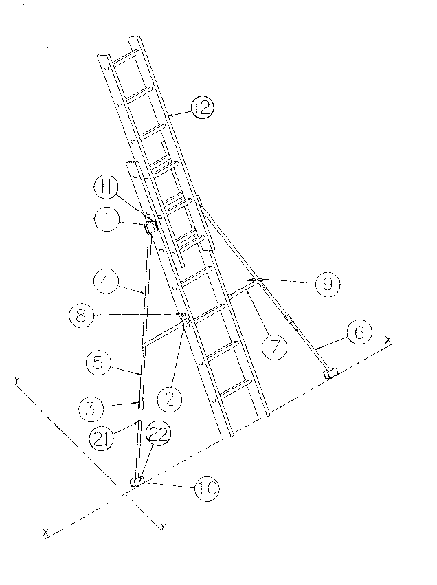
FIG. 1 is a perspective view of an extension ladder
incorporating the two leg supports assembly of the present
invention;
FIG. 2 is a drawing of the top support attachment for top tube
supports;
FIG. 3 is a drawing of the bottom support attachment for
straight lateral brace;
FIG. 4 is a detailed cross-sectional view of the adjustment
ring;
FIG. 5 is a drawing of the straight lateral brace and the
spring lock pin showing the connection with the telescopic
tube support.

21 18436
0 DESCRIPTION OF T~E PREFERRED EMBODIMENT
In accordance with the invention, to the ladder 12 in FIG. 1
is attached to the almost upper end of lowermost section of
the ladder a spacer template 11 for bolting pattern to the
ladder side rails and a first metal support attachment 1, the
detailed configuration of which is best seen on drawing in
FIG. 2.
Referring to FIG. 2, fitted into the U-shaped spacing of a
first metal support attachment 1 is a flattenned end of top
tubing 4 which is drilled for receiving a hinge pin 13 or bolt
connection to allow rotation only in one axis.
~eferring to FIG. 1 and 3, a second metal support attachment
2 is attached to the ladder side rails by bolting or riveting.
This support attachment has a hinge pin 14 or bolt to allow
vertical rotation of straight lateral brace 7, see details on
FIG. 5, which is also connected to the top 4 and bottom 5
telescopic tubes at the same time in the same hole using
spring lock pin 9. It is important to mention that spring lock
pin 9 is only installed by ladder user when using the ladder
for his own utility. FIG. 5 refers how this connection is
being assembled.
Further enhancing the ability to stabilize the ladder is the
use of non-sliding footpads 10 in Fig. 1, which will be
oriented at a perfect angle to allow a best friction grip on
the ground. The footpad is attatched to the bottom tube 6 by
the use of hinge pin 22 or one bolt connection to allow
3 rotation along the leg support space angle.
Now referring to FIG. 1 and 4, is the detailed drawing of
adjusting ring 3 for fine adjustment to the length of the leg
.~
`~

2 1 1 8 4 35
o support. The adjusting ring 3 is made of a threaded rod
coupler 15 and short threaded rods 16 and 17 which are
connected to tubing supports 5 and 6 by bolting or riveting.
Either short threaded rod 16 or 17 is to be glued with five to
six internal fillets from threaded rod coupler for secured
connection.
From mounting to storage position, spring lock pin 9 is first
removed from the three holes connection shown on FIG. 5, hole
18 from lateral brace 7, one of the holes 19 from top tube
10 support 4 and one of the holes 20 from the bottom tube 5. Then
lateral brace 7 and the leg support assembly 4, 5, and 6 in
Fig. 1 will collapse against the ladder rails. The tubing
support can be fastened to the ladder side rail using a third
metal support attachment 8 when being transported or stored.
15 The brace 7 which is then parrallel to support tubings 4, 5
and 6, is secured into support tubing 6 using spring lock pin
9 as locking mechanism in hole 21 of Fig.1.
This invention has been described herein to provide those
skilled in the art with the information needed to apply the
novel principles. Nowever it is to be understood that the
invention can be carried out by specially different equipment
and devices, and various modifications can be accomplished
without departing from the scope of the invention itself.
3o

Representative Drawing
A single figure which represents the drawing illustrating the invention.
Administrative Status

2024-08-01:As part of the Next Generation Patents (NGP) transition, the Canadian Patents Database (CPD) now contains a more detailed Event History, which replicates the Event Log of our new back-office solution.

Please note that "Inactive:" events refers to events no longer in use in our new back-office solution.

For a clearer understanding of the status of the application/patent presented on this page, the site Disclaimer , as well as the definitions for Patent , Event History , Maintenance Fee  and Payment History  should be consulted.

Event History

Description Date
Time Limit for Reversal Expired 2011-10-19
Inactive: Adhoc Request Documented 2011-07-21
Letter Sent 2010-10-19
Small Entity Declaration Determined Compliant 2007-10-17
Extension of Time to Top-up Small Entity Fees Requirements Determined Compliant 2007-10-11
Inactive: Office letter 2007-10-11
Inactive: Office letter 2007-07-13
Inactive: IPC from MCD 2006-03-11
Inactive: Late MF processed 2005-10-26
Letter Sent 2005-10-19
Inactive: Office letter 2005-10-17
Inactive: Office letter 2002-06-21
Change of Address Requirements Determined Compliant 2002-06-21
Grant by Issuance 1997-02-18
Application Published (Open to Public Inspection) 1996-04-20
Request for Examination Requirements Determined Compliant 1994-10-19
All Requirements for Examination Determined Compliant 1994-10-19

Abandonment History

There is no abandonment history.

Maintenance Fee

The last payment was received on 

Note : If the full payment has not been received on or before the date indicated, a further fee may be required which may be one of the following

  • the reinstatement fee;
  • the late payment fee; or
  • additional fee to reverse deemed expiry.

Please refer to the CIPO Patent Fees web page to see all current fee amounts.

Fee History

Fee Type Anniversary Year Due Date Paid Date
MF (patent, 4th anniv.) - small 1998-10-19 1997-08-21
MF (patent, 5th anniv.) - small 1999-10-19 1999-08-04
MF (patent, 6th anniv.) - small 2000-10-19 2000-10-15
MF (patent, 7th anniv.) - small 2001-10-19 2001-08-02
MF (patent, 8th anniv.) - small 2002-10-21 2002-08-16
MF (patent, 9th anniv.) - small 2003-10-20 2003-08-08
MF (patent, 10th anniv.) - small 2004-10-19 2004-08-03
MF (patent, 12th anniv.) - small 2006-10-19 2006-09-18
MF (patent, 13th anniv.) - small 2007-10-19 2007-08-02
MF (patent, 14th anniv.) - small 2008-10-20 2008-08-08
MF (patent, 15th anniv.) - small 2009-10-19 2009-08-25
MF (application, 2nd anniv.) - small 02 1996-10-21
Owners on Record

Note: Records showing the ownership history in alphabetical order.

Current Owners on Record
FRANCOIS CHARBONNEAU
Past Owners on Record
None
Past Owners that do not appear in the "Owners on Record" listing will appear in other documentation within the application.
Documents

To view selected files, please enter reCAPTCHA code :


To view images, click a link in the Document Description column. To download the documents, select one or more checkboxes in the first column and then click the "Download Selected in PDF format (Zip Archive)" or the "Download Selected as Single PDF" button.

List of published and non-published patent-specific documents on the CPD .

If you have any difficulty accessing content, you can call the Client Service Centre at 1-866-997-1936 or send them an e-mail at CIPO Client Service Centre.


Document
Description 
Date
(yyyy-mm-dd) 
Number of pages   Size of Image (KB) 
Abstract 1996-04-20 1 31
Cover Page 1996-06-10 1 14
Description 1996-04-20 7 266
Claims 1996-04-20 3 129
Drawings 1996-04-20 3 65
Claims 1996-06-13 3 129
Drawings 1996-06-13 3 65
Cover Page 1996-06-13 1 14
Abstract 1996-06-13 1 31
Description 1996-06-13 7 266
Cover Page 1997-02-18 1 12
Description 1997-02-18 6 266
Abstract 1997-02-18 1 35
Claims 1997-02-18 3 111
Drawings 1997-02-18 3 65
Representative drawing 1999-08-04 1 23
Notice: Maintenance Fee Reminder 1997-08-04 1 119
Notice: Maintenance Fee Reminder 1999-07-20 1 120
Notice: Maintenance Fee Reminder 2000-07-20 1 118
Notice: Maintenance Fee Reminder 2001-07-23 1 120
Notice: Maintenance Fee Reminder 2002-07-22 1 130
Notice: Maintenance Fee Reminder 2003-07-22 1 115
Notice: Maintenance Fee Reminder 2004-07-20 1 119
Notice: Maintenance Fee Reminder 2005-07-20 1 117
Maintenance Fee Notice 2005-11-02 1 173
Late Payment Acknowledgement 2005-11-02 1 166
Notice: Maintenance Fee Reminder 2006-07-20 1 119
Notice: Maintenance Fee Reminder 2007-07-23 1 121
Notice: Maintenance Fee Reminder 2008-07-22 1 122
Notice: Maintenance Fee Reminder 2009-07-21 1 119
Notice: Maintenance Fee Reminder 2010-07-20 1 123
Maintenance Fee Notice 2010-11-30 1 170
Second Notice: Maintenance Fee Reminder 2011-04-20 1 121
Notice: Maintenance Fee Reminder 2011-07-20 1 121
Fees 2003-08-08 1 66
Correspondence 2002-06-21 1 12
Correspondence 2002-05-29 1 30
Fees 2002-08-16 1 76
Fees 2000-10-15 1 74
Fees 2001-08-02 1 55
Fees 1999-08-04 1 69
Fees 2004-08-03 1 65
Correspondence 2005-09-23 1 27
Correspondence 2005-10-17 1 13
Fees 2006-09-19 1 61
Correspondence 2007-06-15 1 27
Correspondence 2007-07-13 1 12
Correspondence 2007-06-15 1 28
Correspondence 2007-10-11 2 34
Fees 2007-08-02 1 70
Correspondence 2007-10-17 1 27
Correspondence 2007-10-17 1 29
Fees 2008-08-08 1 60
Fees 2009-08-25 3 180
Fees 1997-08-21 2 96
Fees 1996-10-31 2 100
Fees 1995-10-02 1 30
Fees 1995-09-21 3 102
Prosecution correspondence 1996-08-20 4 213
Prosecution correspondence 1996-08-20 4 171
Prosecution correspondence 1996-08-06 2 74
Prosecution correspondence 1996-08-28 3 105
Prosecution correspondence 1995-12-21 3 94
Prosecution correspondence 1995-02-14 8 252
Prosecution correspondence 1996-05-28 5 231
PCT Correspondence 1994-11-16 2 66
Prosecution correspondence 1996-03-27 5 268
PCT Correspondence 1994-12-05 1 45
Courtesy - Office Letter 1996-03-18 1 29
Courtesy - Office Letter 1995-01-18 1 16
Courtesy - Office Letter 1995-01-18 1 15
Courtesy - Office Letter 1996-01-17 1 38
Courtesy - Office Letter 1996-09-13 1 22
Courtesy - Office Letter 1996-11-04 1 14
Examiner Requisition 1996-07-23 4 178
Examiner Requisition 1996-04-29 3 176
Examiner Requisition 1996-03-08 4 137