Note: Descriptions are shown in the official language in which they were submitted.
2 ~ 3 ~
8 P E C I F I C A T I O N
TI~LE :
~'~ETHOD AND APPARATU~ li'C)R SOLDERING ::
A COIL WINDIN~I WlE'cE ~1!0 A ~ERMINP~I. PIN"
~: 5 BACRGROUND OF l!llE INVENI'ION
The present invention generally relates to soldering.
More specifically, the present invention relates to soldering a
wire to a terminal pin with a noncontacting heat source. ;
;~ It is generally known to contact the terminal pins to
~ 10 the winding ends of coils, e.g., relay coils, by immersion of the
,
pinC respectively wound with the winding ends in a solder bath.
However, wi~h this method, a fluxing agent is re~uired in order
to assure~reliable soldering.
Unfortunately, fluxing agents and solder baths release
~15~ toxia vapors. Furthermore, fluxing agent residues can damage ~;
nelgh~oring contaat ~urraces. In t~e relay, Por instance, such
damage aan cause an outage o~ the relay during later operation,
Moreover, traditidnal solder baths have operating temperatures o~
approximately 350C and are, therefore, subject to pronounced
scaling o~ their sur~ace resulting in great quantities o~ waste
~older.
~,
In an effort to elimlnate the need for undesirable
fluxing agents, it i~ know to ~use winding ends to respective
terminal pin~ with light probe welding under a proteative
. .
atmosphere ~hereinafter referred to as "WIG" welding). Such a
method is disclosed in German published application 2 063 535.
~ Under certain circum tances, however, the high welding
; temperature sub~ect the a~sociated coil to an excessively high
thermal load.
Also, U.S. Patent No. 4,039,801 (which claim~ priority
based on German ~ublished application 2 301 094) relates to tha
use o~ a pre-tinplated ! terminal pin in a process of arc welding a
. ''
~` . 2118~Q~ , ~
section of wound wire thereto. A layer of solder is provided on
the pin. The solder, however, is used to position the wire. The
permanent contacting is the result of welding at a tin welding
temperature.
There~ore, a need exists for an improved method of
soldering a winding end to a terminal pin wikhout the use o~ a
~; fluxing agent. Furthermore, a need exists for such a method
.,
which avoids high welding temperatures with the corresponding
thermal load.
t~UMM~BY OF q!HE INV~NTION
The present invention provides a method for soldering ~;
. .
terminal pins to coil winding ends which does not require the
undesirable~use of fluxing agents. Furthermore, the present
invention provides a method for soldering which does not subject
~the~assoc1ated coil to excessively high thermal loads. To~this
end, in an embodiment, a method for soldering is provided
including: wrapping a winding wire around a terminal pin;
contacting the terminal pin with an amount of solder fres of
luxing agents; and melting the solder at soldering temperature
under a protective atmosphere by a heat source.
In the method of the invention, thus, the solder is
separately supplied and is then melted over the winding wire
; wound onto the terminal pin. The employment o~ a fluxing agent
is avoided due to the protective atmosphere. The heat source can
be a device used for traditional welding. However, according to
the present invention, only a solAering temperature is reached at
the terminal pin, for example, 300-400C.
In a preferred embodiment, heat is applied with an arc
under a protective atmosphere (WIG arc). The activation time of
the arc iB dependent on the thicknesses of khe materials -~
employed. For example, ~or a standard kerminal pins having a
diameter of 0.6 mm, an arc activation time o~ a approximately
-- . 2~
..... .. .
~ ..
100-200 msec i~ adequate g~lven an arc current of appraximately of ~
2 Amperes. Because the arc power is low and short arc time, ';
temperatures are lower than those reached during traditional ~-
welding. This results in lower thermal loads on the metal wire -
coil windings and the coil base, which can be plastic.
In an embodlment, the heat source a laser which direct~
a laser beam onto the terminal pin and soldering area.
According to the present invention, the solder can be
supplied in various ways after the wrapping of the winding wire.
~lG In an embodiment, the pin tips are briefly immersed into a solder
bath whose temperature lies only slightly above the melting point
of the solderO Practically no scaling occurs given such a low
temperature of the solder bath. ~ ;-
~he pins are dipped only slightly into the bath; the
: ",,
~ 15~ wrapped winding end is also not soldered during immersion.~ As a
: . - .
result, an su~ficient quantity of solder adheres to each immersed
; terminal pin end by cooling in the form of a drop. When the heat
is applled, this amount of solder flows in a bulbous mass over
the region o~ the wrapped wire. ~ -
Inianother"embodlment, the predetermined quantity of ~;
solder is provided in ring shape. Such a ring can be cut from a
tubular piece. The ring is placed onto the ~ree end of the
terminal pin. This solder ring can subsequently be melted by
application of a heat source under a protective atmosphere, as
set forth above.
In another embodiment, the solder is provided in the
form of a wire. A respective end section of the solder wire is ~-
brought into contact with the terminal pin and is then melted
o~f.
In a related embodiment, the solder wire can be
supplied via a special device provides the solder wire within a
guide tube. The device advances an appropria~e predetermined~end
--`- 2 ~ 3
,, ;~,
length of the solder wire which is brought into contact with the
terminal pin. The guide tube can have an extension that supports
a ~ide of the solder wire end section, but openly exposes the
; ~ solder wire to the terminal pin and the heat source.
Therefore, it is an advantage of the present invention
-~ to provide an improved method of soldering a winding wire to a
terminal pin.
Another advantage of the present invention is to
provide a method of soldering which does not generate high levels
"
of heat.
A ~urther advantage of the present invention is to
provide a method of soldering which avoids subjecting a coil to
; exces ively high thermal loads. ~'
Still another advantage o~ the present invention is to ~f
15;~ provide method o~ soldering wherein plastic o~ a coil base'is
only slightly stressed in comparison to a traditional welding
process. ;~
; Moreove~, an advantage of the present invention is to
provide a method of soldering wherein the electrode wear ls also
~; lowiin comparison to!known weldlng methods.
A ~till ~urther advantage o~ the present invention is ~;
to provlde a method of solderiny which avoids the use o~ a `~
luxing agent.
Yet another advantage of the present invention is to
provide an improved device ~or supplying, advancing and
contacting a predetermined length of solder wire agalnst a
terminal pinO
Additional features and advantages of the present
invention are described in, and will be apparent ~rom, the
detailed descrlption of the presently pre~erred embodiments and
from the drawings.
j 1~8~
, ,
BRIE:F DE~3CRIPTION OF TRE DRi~WINGB
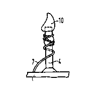
FIG. 1 is a perspective view of a relay coil which can
be soldered hy the method o~ the present invention.
FIG. 2 is an elevated front view of a terminal pin on
the coil oP FIG. 1.
FIG. 3 i~ an elevated side view of the terminal pin o~ -
FIG . 2 .
; FIG. 4a is an elevated side view of the terminal pin of
FIG 3 having a winding end wrapped therearound.
FIG. 4b is an elevated side view oP the terminal pin of
FIG. 4a wherein a tip of the terminal pin has a drop of soft --~
... . ......
solder applied thereon accordiny to a method of the invention.
FIG. 4c is are each~an elevated side view of the ;~;-
terminal pin o~ FIG. 4b where the solder drop has been melted to
5~ ; flow over~the wrapped winding end. '
FIG. 5a is an elevated ~ront view of a coil having
winding ends wrapped around respective terminal pins.
PIG. 5b~i6 an elevated front vlew the coil o~ FIG. 5a
, ;~: . ,
po~itioned above a solder bath a~ter tlps oP the terminal pins
haveidipped therein,,llaccording to a method of the present ~,f
invention.
FIG. 5c i8 an elevated ~ront view o~ the coll o~ FIG. ~,
5b, turned over, positioned proximally to a welding apparatus in
accordance with a method o~ the present invention.
FIG. 6 is a schematic illustration o~ a WIG soldering
arrangement wherein a solder wire is supplied through a guide
tube according to an embodiment o~ the present invention.
FIG. 7a is a sectional view taken general'ly along line
VIIa-VIIa o~ FIG. 6.
FIG. 7b is a sectional view taken generally along line
VIIIb-VIIIb o~ FIG. 6.
2 1 ~
FIG. 8 is a schematic top plan view generally from line
VIII-VIII onto the wire delivery mechanism of FIG. 6.
FIG. 9 is an elevated side view of a terminal pin
having solder supplied in ring form according to a method of the
present invention. ;~
pETAILED DE~CRIPTION OF ~HE
PREBENTLY PRE~R~ED FM~ODIM N~
In accordance With the invention described wherein lik~
numerals designate like parts, FIG. 1 shows a relay coil 50 a~ an ~ ~i
example of a type of relay coil with which the method o~ the ~- ;
invention can be applied. The coil 50 has a base 1 having two ~;
flanges 2 and 3. The base 1 can be plastic. The flanges 2 and 3
;~ each have a respective terminal pin 4 and 5 anchored therein. ;. ,~,' ''',.,! '
The colI me~ber 50 has a winding 6 in a spooled manner between
15~ the Planges 2, 3. A first winding end 7 o~ the winding 6 is ~-
wrapped and soldered to the upper end of the terminal pin 4. ~.
Similarly, the winding 6 has a second winding end 8 wrapped and
eoldered to an upper end o~ the terminal pin 5.
Referring to FIGS. 2 and 3, the end section of the
~20 términal pin 4 is shown anchored in the flange 2. The terminal
pin 4 is generally cylindrical, but is partially crimped ~olform
a flat zone 9. ~he terminal pin 5 is similarly shaped.
FIGS. 4a, 4b an~ ~c show dif~erent phases durlng
; contacting between the terminal pin 4 and winding end 7. In FIG.
4a, the wlnding end 7 is wrapped around the terminal pin 4,
particularly around the flat zone 9, with a few turns.
The winding end 7 is preferably wrapped in a manner
whereby~it remains anchored firmly in position and does not ~ndo
by itself. Next, as shown in FIG. 4b, a soft solder drop 10 o~ a
speaific predetermined quantity is then brought into contact with
the terminal pin 4. Application of the drop 10 occurs according
to an immersion operation illustrated in FIG. 5b, so that the
211~83
supplied quantity of solder remains adhering to the ~ree end o~
the terminal pin 4 as the solder drop 10.
The soft solder drop 10 is then heated to soldering
temperature, i.e., to approximately 300-400C, with a welding ~;
system under a protective atmosphere. When heated, the solder
~ drop 10 melts and flows over the region of the wrapped winding
; end 7. The solder cools and solidifies forming a bulb 17, as
shown in FIG. ~c. The insulatlng lacquer of the winding end 7
melts off during heating, so that the winding wire 6 is re}iably
mechanically and electrically connected to the terminal pin 4.
FIG. 5a again schematically shows a coil member 1
having the terminal pins 4 and 5 having the respectively wrapped
winding ends 7 and 8. -~
~5~ FIG. 5b illustrates a means of supplying the soft
solder drop 10 to the terminal pins 4 and 5. As shown, a ~older
; bath 11 is provided for this purpose, a so~t solder 12, for ~i-
example a lead-tin solder, being located therein. This solder 12
is maintained at a temperature only slightly above the melting -
point of the solder. For example, a Sn-Pb solder having a
melting po~in~ of 18~C is held at a temperature of approxlmately
186C in the solder bath 11. The solder 13 has an oxide-~ree
surfac0 at this low temperature and is there~ore espeoially
advantageous for ~oldering without a ~luxing agent. The low
processing temperature enables constant and long-duration yield,
so that praatically no solder wastes arise in the bath.
According to FIG. 5b, the coil 50 has the tips of the
terminal pins 4 and 5 dipped into the solder 12, as indicated by
the arrows. The soft solder 12 therein solidifies against the
cooler terminal pins 4, 5, forming the drops 10 thereon.
In an embodiment, as shown in FIG. 5c, the solder drops
10 are melted with a WIG welding torch 13. The welding torch 13
is used to heat the solder drop lo, terminal pin 5 and the
,
'~
winding end 8 to a temperature. A welding curren~, for example
on the order of magnitude of two amperes or more, is applied
between the electrode 14 and the terminal pin 5 in order to
ignite an arc having a duration of, ~or example, 200 msec.
At the same time, a protective gas or protective
atmosphere, e.g., argon, is blown onto the solder location via a
protective atmosphere nozzle 16. The protective atmosphere
prevents scaling and oxidation at the connecting elements despite
the relatively high soldering temperatures of the arc. During
lo the operation, the drop 10 flows to ~orm the bulb 17 as shown in
FIG. 5c at the terminal pin 4.
The actuation time o~ the arc can be between loo and
300 msec for a typical pin 4 where the arc has a power of 2
Amperes. However, depending on materials and thickness, the time ~;
andjor power can be selectively adjusted in order to reach,the
required-soldering temperature. As mentioned above, the
soldering temperature is usually around 300-400~C, or the
temperature su~ficient to melt the solder without damaging the
winding ends 7, 8 or terminal pins 4, 5. Pre~erably, the
soldering temperature is lower than the melting point of the
, ~ j , i I ` ;,
winding ends 7, 8 and terminal pins 4, 5.
In another embodiment, a laser 40 can be used as the
heat source. The laser 40 directs a laser beam onto the wrapped
; region to melt the solder at the soldering temperature.
FIGS. 6-8 show another embodiment o~ the soldering
method o~ the invention. In this embodiment, the solder i8
supplied in wire form instead o~ in a bath. As in the preaeding
exemplary embodiment, the terminal pin 4 has the wrapped winding
end 7 positioned proximal to a WIG welding torch 13 and the
electrode 14 thereof. In this case, too, a constant current
source 15 is connected for generating the welding current. Also,
23.i~4~
'"'''' ,~ ,' ' '' ~,
the protective at~osphere 18, such as argon, is blown onto the
solder location via a protective atmosphere nozzle 16.
The solder in the embodiment of FIG. 6 i5 supplied in
form of a solder wire 21. More specifically, the solder wlre 21
` 5 is provided via a guide tube 22 which holds the solder wlre 21
concentrically therein. The guide tube 22 includes an exten~ion
23 which project~ in an axial direction thereProm. The extension ~ ,
~; 23 is generally a quarter-section o~ a tube shape, as shown in
FIGS. 7a and 7b. The extension 23 can support an end section 21a
of the solder wire 21, a side o~ which is openly exposed toward -~;
the terminal pin 4 and is upwardly exposed toward the heat -
source. ~i-
T~e guide tube 22 is pivotally mounted to rotate around ;~-
an axis 24, as illustrated in FIGS. 6 and 8. The guide tube 22
;5~ Gan~thereby be rotated to press the end section 21a of the'solder ~ i~
wlre again~t the terminal pin 4. A spring 25, as illustrated in
F~G. 8, aan, ~or example, be used to bias the guide kube 22 to
rotate in this manner. Furthermore, the ~older wire 21 is pushed
through the guide tube 22 via a ~eed device 26 which can include
a plurality o~-rolle~s.~
; During the solderiny process, a respectively speci~ic
predetermined length o~ the solder wire 21 is pushed through the
guide tube 22 with the assistance o~ the feed device 26, so that
the solder wire 21 is po~itioned adjacent to the free end of the
terminal pin 4 and can be brought into contact with the pin 4 by
the spring 25. Vertical positioning between the terminal pin 4
and the end section 21a can also be adjusted i~ necessary to be
held slightly above the ~lat zone 9, as illustrated in FIGS. 6
and 7a. ;~
The electrode 14 o~ the WIG welding 'corch 13 is also
positioned proximal to the terminal pin 4 and generally above the
guide tube 22. As illustrated in FIG. 6, thelelectrode 14 has ~ ~;
''~'"
`` 2J.1~3 ~
":~"
its end offset somewhat in the direction toward the guide tube 22
relative to an axis of the terminal pin 4, so that an arc 18 i5 . ,
ignited at this side of the terminal pin facing toward the guide -
tube 22. The solder wire 21 is melted by the arc 18. The end ~ :
SeGtion 21a melts and adheres to the terminal pin 4 where it
cools to form the bulb 17, as shown in FI~. 4c. ~-
In order to avoid an adhesion of the remaining aolder
wire 21 to the terminal pin, the solder wire 21 is pulled back
through the feed device 26 during activation of the arc. For
lo~ example, the on-time of the arc can be approximately 300 msec for -
:~ :
a particular thickness of the terminal pin 4. Thus, the solder
wire 21 is praferably expediently retracted after ap~roximately,
200-msec on-~ime, whereas the arc continues to burn for
,
approximate~y 100 msec layer.
~ ~In a further embodiment, FIG. 9 schematically
illuskrates yet another means of applyiny a predetermined
quantity of solder to the terminal pin 4 wherein the solder is
provided in the ~orm of a ring 31. The melting then ensues in
the same way as in the preceding examples.
It~should!be understood that;variouslchanges and
modifications to the presently preferred embodimonts described
herein will be apparent to those skilled in the art. Such
changes and modi~ications may be made without departing from the
~; spirit and scope of the present invention and without diminishing ~;
its attendant advantages. For example, a laser can be used as
the noncontacting or nonconducting heat source in lieu of the
welding torch. Also, the method of soldering can be used on a
device having more or fewer terminal pins than shown in the
Figures. Furthermore, the invention is not limited to use on
coils~ It is, therefore, intended that such changes and ~-
modifications be covered by the appended claims.
",