Note: Descriptions are shown in the official language in which they were submitted.
. WO93/21593 ~ 9 PCT/US93/03590
!
,
~LF,~TRONIC CO~TRO~R FOR
A GLASSWARE FORMlNG MACHINE
BACKGROUND OF THE INVENTION
The present invention concerns a computer-based systeln
for synchronizing and controlling the operations of a
glassware forminy machi~le. The glassware forming maclline
includes a number of individual sections w}~ich receive molten
glass from a furnace or forehearth to be molded into a
particular glassware article. The article or ware is passed
by way of a transfe~ conveyor to a lehr for annealing the
glass. The present invention thus contemplates a
computer-based system for scheduling the operation of each
section and its m~chanical components, and for providing
access by the machine operator to modify the glassw~re
formin9 sequence an~ timing of events.
A typical glassware forMing machine includes a plurality
oi sections which are each capable of manufacturing glassware
by itself. The sections are operated in synchronism
: according to a particular phase relationship between each
section in order to permit the plurality of sections to
o~tain gobs of molten glass from a single source in an
ordered sequence. Each section then for~s these acquired
gobs of molten glass into a number of finished glassware
articles which are then delivered to an output conveyor,
again in sync~lronized fashion. While one section is
delivering glassware to the conveyor, another section may be
engaged in a different step in the formation of the glassware
article. When properly timed and phased, wholly formed
glassware articles are produced by each sèction and passed in
an orderly fashion onto the conveyor which transports tlle
glassware articles to a stacker, and ultimately to a lehr for
annealing.
.
WO93/21593 )~11 8 5 1 PCT/US93/03590 ~-~
The glassware forming machine, and each section includes
a n~lmber of functional componellts or mechanical devices which
perform each of the steps ill the glassware forming
operation. For instance, the machine includes a feeder for
acquiring moltell glass from the forehearth and passing tlle
molten glass to a gob distributor. A shear cuts the mol~en
glass illtO measured gobs. rhe gob distributor includes a
number of scoops which are used to convey tlle measured gobs
to one of the number of sections associated with the gob
distributor. Separate mo~ors are used to drive the feeder,
shear ana gob distri~utor.
Each section also includes a number of mechanical devices
which can ~e pneumatically, hydraulically or electrically
controlled. For instance, each section receives the molten
ylass and includes a component for moldiny the glass, or
blowing the glass, into a glassware article. The glassware
article is typically formed in a section and then transferred
to a dead plate which can include the component for blowing
cooling air onto the glassware article. A pusher assembly is
use~ to push the gla3sware article from the deadplate onto a
moving conveyor adja~ent the IS machine. Each sections may
` include means for forming more than one glassware article.
Thus, the pusher may also include a number of arms for
simultaneously pushing the number of glassware articles from
the deadplate onto the conveyor in unison. Each of the
mechanical devices of the IS machine is typically commanded
by a valve block which signals the operation of each of the
components in an appropriate timed sequence.
In a typical glassware ~orming machine, multiple sections
fee~ glassware articles onto a common conveyor. Each of ~he
s~ctions may produce up to four articles of glassware at a
time. Thus, throughout a single cycle of the glassware
forming system, multiple glassware articles can be produced
by the totality of the IS machine. These glassware articles
must be properly formed and properly passed to the conveyor
- WO93~1593 PCT/U~93/03590
`'~ ~ 1 g 5 9
so that no conflict results--that is, so that glassware
articles do not crasll inl;o each other as they en~er the
transport conveyor~ lhe operation of the glassware forming
system requires precise timing of each of the steps of the
glassware forming process includillg formation of the molten
go~, distribution of the go~ to each section, formation of
the g1assware article in each section, and tranfiport of the
finished article to the transfer conveyor and ultimately to
the lehr.
In past years, cwTIbersome systems of cams, drum timers
an~ echanical linkages were used to provide the proper
tilllin~ and se~uence of events for each of the mechanical
components of the glassware forming system. In recent years,
however, electronic timing has replaced the prior mechanical
systems, and solving many of the problems associated with
those systems. Electronic timing and synchronization
provi~es more accurate control of the glassware forming
process and greater flexibility in manipulating or changing
the s~qllence and timing of glassware forming events.
For the purposes of the following disclosure, a number of
terms will be defined which are frequently used in the
g~assware forming art. In the ar~, a C'shop" is a particular
glassware forming machine. This glassware forming machine
includes a multiple number of individual sections. A n shop
cycle" is the amount of time required for a complete cycle of
all events for all of the individual sections forming the
shop. For convenience, and configuration purposes, a
complete shop cycle has been defined in the art in terms of
degrees from 0.1 to 359.9 deg-ees, usually in 0.1 degree
incrementS.
~ n "event" is used to designate a step in the glassware
forming process. More specifically, an event is the
as~ociation of a particular output to change the state of a
mechanical devicP at a certain angle in the shop or section
cycle. Each event has an "on angle" and an "o~f angle" to
WO 93/215g3 ~ 1 1 8 ~ 1 g PCT/US93/03590 -. -
designate when the paLticu1ar event begirls and ends. For
each event, and more specifically for each particular outplit,
a signal is sent to a devi.ce controller which is used to
acti~ate or de-activate tlle motors, valves, solenoids, etc.,
driviny the actual mechanical components of the sho~. Each
mechanical device of eYery section of t~ie shop will have an
output associated with it, and the operation of each of these
componen~s will have a specific event associated with it.
Each of the IS machines is operated in a "firing order".
This firirlg order constitutes the order in which each section
receives gobs from tlle gob dist~ibutor. As each section is
activated in the firing order sequence, each section
commences operation at a different angle in the shop cycle.
This angle is known as a "section differential offset" which
represents the delay from the beginning of the shop cycle
befnre the individual section begins its OWIl glassware
forming cycle. Each section also operates in a cycle from
receiving the glass gob to forming the glassware article to
pushing the ar~icle onto the transfer conveyor. Each section
cycle ha.s the same duration as the shop cycle so that
synchronization is important between the shop and section
cycles .
1,
WO93/~lS93 PCT/US93/03590
' 1 .tX~19
--5--
B~IE~ I~E~CRI~ITION OF 'lHE DR~WING~
FIG. 1 is a pictorial representation of t~le ~asic
components of the timing an~ control s~rstenl for a ~lassware
forming machille in accor~a~lce witl~ tl~e present invention.
~IGS. 2A and 2B are pictorial represerltations of tlle
t iming and control system of the pr~sent invention confiyured
for single sho~ and multiple shop control, respec~ively.
FIG. 3 is a depiction of the primary menu screen
implemented by software in the timing and control system of
the present invention.
FIG. 4 is a depiction of anvther menu screen iln~)lemented
by ~he invention and particularly showing a help feature of
t~e system.
FIG. 5 is a depiction of another menu screen implemented
~y the inventive system permitting user configuration of the
glassware forming shop.
FIG. 6 is a depiction of another menu screen permi~:ting
user configuration of the stop states of mechanical
componen~s of a mac}line section.
FIGS. 7A and 7B are depictions of menu screens which
permit user input to change or jog on and off angles for
event groups or specific events in the glassware forming
cycle.
FIG. 8 is a depiction of a screen display in which timing
25 information ~or a shop is graphically represented.
FIG. 9 is a depiction of a menu screen implemented by t~le
present inverltion to implemerlt con~lict testing and detection
procedures within tlle system software.
FIGS. 10A and 10B are graphs illlsstrating the conflict
G 30 testing protocol implemented by the present invention witl
E'IG. lOA showing a timing configuration resulting in no
. .
corlflict and FIG. 10B showing a modified timing configuratios
resulting in a conflict ~etection.
FIG.ll is a depiction of a screen displayis~g productior~
W093/21~93 PCT/US93/03S90 -~
~1 ~8519 -6-
re~ort inforlnation concerni11g ~he performaJlce of a glassware
fornlin~ shop.
E'IGS. 12A~ aIe flowch~rts showing e~ch ~f the
su~routines implemented by software wi~hin the timiny and
control system of the present invention.
FIG. 13 is a block representation of the configuration of
mernory locations in the present invention utilized to
provided linked lis~s of events which impleme11t the sequence
and timing functions of the timing and control system of the
10 p~esent in~ellLion.
_ W093/21~93 PCT/US93/03590
.~ `3
DESCRIPTION 0~ lHE ~REFERRED EMBODIMENT
For tlle purposes of promoting an understan~ y o~ the
principles of the inventioll, reference will now be nlade to
the em~odiment illustrated in tlle drawin~s and specific
language will be used to descri~e the same. It will
nevertlleless be understood that no limitation of ~he scope of
the inventioll is ~hereby intended, sucll alterations and
fur~her modifications in the illustrated device, an~ such
further applications of tlle principles of the inven~ion as
illustrated therein being contemplated as would normal~y
occur to one skilled in the art to which the inventiQn
relates.
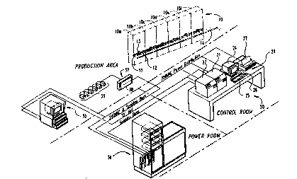
FIG. 1 shows the b3sic components of one embodimellt of
the timing and control system for a glassware forming systern
~ the p~esent invention. FIG. 1 shows a typical
configuration for one shop 10 which is made up of six
sections lOa-lOf. The shop also includes a ~orehearth for
producing molten ylass, a ~eeder, a shear, a gob distributor,
a ~ransfer conveyor, a stacker, and a lehr, althougll these
components have not ~een depicted in FIG. 1. The timing an-
~sequence of operation of these shop ~evices is pre~erably
controlled by the timing and control system of the pres~nt
invention.
The ~eadplates 11 for each section have been shown, as
well as a pusher assem~ly 12 which includes a num~er of arms
13 ar transferring finished glassware articles from the
deadplate 11 to a movirly col-veyor 14. Each section as well
as the ~emaining gLassware handling mechanical devices of t~le
shop can be constructed as known in the art. It is
l~ 30 understood tllat tlle timing and control system of the presellt
i ~ inven~ioll can be adapte~ fnr use in controlling a variety of
- shop configurations and IS machine components.
l'l~e central component o~ tlle timiny and control system o
the present inventioll is the shop computer system 20 which is
WO93/21~93 PcT/uS93/03590 -
situated within a control room separate from the mechanical
glassware forminc~ component:s or the shop itself. Il~
accordance wi~h the preferred embodiment, t~e S~IOp cvmputer
20 includes a master computer 21 and a shop control computer
22~ Each of ~hese computers 21 and 22 may be an
IBM-compatible microcomputer, such as a 4~6 compu~er operated
at 33 Mhz. The function of the master and ~ontrol computers
21 and 22, respectively, will be described more fully
herein. Inclllded with the shop computer is a user-interface
~3 which includes a monitor 24, a keyboard 25, a "mo~se" or
¦ ~trackball" 26 and a printer 27. Each of these latter
components provides a user-friendly interface for entering
new information for controlling the timing and sequence of
events, for receiving information concerning the status of
th~ operation of the glassware forming shop and for the
passage of other in~ormation such as for pr~paring reports
concerning the performance of the shop.
The timing and control system further includes a power
distribution panel 30 which resides in a power room that can
~e separately environmentally controlled. The power
dis~ribution panel provides power to all of the components of
the timing and control system, as well as to all of the
mechanical devices of the IS machine. Preferably, the power
distribution panel 30 is configured to proviae 220 volts to
the components of the shop computer system 20, and 24 volts
to the device controllers and mechanical devices. In
addition,-the power di~stribution system include a battery
backup which allows continued operation of the IS machine
mechanical devices after loss of AC power. This battery
back~tp can be operable for a sufEicient time to allow all of
the Inolten g]ass to be purged from t~le IS machine and to
allow the mechanical components of the machine to be moved to
a predetermined state in the event of a power loss.
A third component of the timing and control system of the
presellt invention is the hot end display 35. The hot end
WO93/21593 PCT/US93/03590
. ~
,~',t ~8~1g
display is essen~ially a gra~ ics console situated on the
sllop floor or in ~he product.ion area near the particular
g]assware formill~ machine l0. The hot end display preerably
includes a "toucll screen" feature (as described more fully
llerein), w~icll facilitates tl~e entry of data by the operator
and is very user-friendly ior the environment wi~hin which
t~le display resides.
The next link of the system is the I/O junction box 37.
This I/O junction box provides power and control si~nals to
the various device controllers and mechanical devices of the
IS nlachines. Preferably, signals received from the shop
computer system 20 and the power distribution panel 30, are
fed to a junction box 3~ which then relays the signals to a
number of serial multiplexer modules 3~ associated with each
section. The use of the serial multiplexers 39 reduces the
wiring requirements and provides a more efficient means of
providing power and control signals to each of the mechanical
components of all sections. This particular feature of the
present system is described more fully in co-pending patent
application Serial No. 654,296 ~iled on Feb. 12, l99l in the
name of inventor Anthony Clark and assigned to the assignee
of the present invention. As described more fully in that
application, ~he junction box 37, and particularly the serial
Illultiplexers 39, greatly reduce the wiring requirements and
complexity from prior electronic timing and control systems.
'i The disclosure of application S.N. 65~,246 concerning this
serial multiplex~er ! .system is incorporated herein by re~erence.
One significant benefit of the present invention is tlle
abi'~ity to con~igure the shop computer system 20 into a S}`lOp
network. For example, a typical glass plant will include a
number of glassware forming shops. These shops may be
forming 'the same o~ different glassware articles. It is
- often desirable to provide a link hetween each shop, for
exa~nple, to ~rovide common set-up data between a number of
35 different shops. In addition, linking eac~l of t~le several
WO93/2l593 ~1 ~ 8 5 ~ 9 PCT/USg3/03~90-~
--10--
shops of a glass ~lant provides a ready means for producillg
production reports for the entire plant.
By way of example wi~l reference first ~o FIG. 2A, th~
control system of t~le present inve~ltion is shown in the
absence oE a shop network. It can be seen that three
diferent shops can include tlleir OWIl COrrespOndilly Cetltral ::
computer and hot end display with an individual disk drive
providing storage capability for each indîvidual shop. On
the other hand with reference to FIG. 2~, a master set-up
computer can be provided (which corresponds to master
computer 21 shown in FIG. 1) which interfaces withl a single
disk drive and a single operator console. In this
configuration, the single master set-up computer communicates
with a number of indi~idual control computers associated with -;
each S}lOp. Each shop still retains its own section control
computer and hot end display; however, information that may
~e common among each of the shops is provided to and from the
master set-up computer and its associated disk drive. This
greatly reduces the amount of computer hardwa~e and software
required for a particular glass plant.
The function of each of the specific components of the
system of the present invention will now be described. The
shop computer system 20, and particularly t~le section
control computer 22, is the main controller for the system
which performs the shop control funct~ons. Tlle s~lop computer
system also provides shop configuration information, as well
as jo~ informatiQn. This job information constitutes all o~
the informatioII necessary to configure ~he shop to pro~uce a
particular type of ware. Job inEorma~ioll can be stored on
the hard disk of the master computer 21 or retrieval at any
time. It is ~ypical ill a glass plant t~lat specific glassware
articles are produced regularly throughout the year. Thus,
the particular timing and control necessary to produce that
g~assware article may be repeated several times for a given
shop. It is therefore preferable to store job setup
.
W093/2l593 Pcr/usg3/o3590
--1 1--
informatiol~ so that the timillg and control of ~le IS machine
for t~le particular job can be ~eadily achieYed by sim~ly
retlieving the job setup inormation, loading it into the
timing an~ control routirles within the shop control comput:er
22 and implemelltirlg th~se routilles.
The shop master computer 21 include a programmable
security lock feature. l'his security lock feature permits
~ersorlnel at the glass plarlt to assign security access levels
for each of the individual control but~ons corresponding to
specific fllnctions of the timing ~nd control system. A
particular shop may have varyiny degrees of security levels
ranging from the operator to a master key level. At the
operator security level, only certain functions o the timing
arld control s~stem can be accessed or actuated by the
operator on the shop floor. For example, a security lock may
prevent the shop operator from being able to char.ge the
overall Liming oE each of the sections of the shop, while
permitting the operator to make modest ~hanges in the timing
of a specific mechanical device of an IS machine. At another ~;
security level, a "setup level", certain personnel of the
glass plant can be permi.tted to input or change information
concerning the initial setllp o~ the ~hop itsel. rl'his setup
in~ormation can include data concerning the physi~al aspects
of ~he IS machin~.
Additional security levels can be provided for the shift
su~ervisor and the production su~ervisor for the glass
plant. At each of!these securi~y levels, the respective
supervisor may be permitted to increase the speed of the
glassware forming system, or more parti~ularly each shop
cycle. ln addi~ion, eacll of the supervisors may ~e permitted
to generate cer~ain report data concerrling the operation of
~he glassware forming machine ~uring a given shift, or during `
a longer period oE time as an indication of the perormance
of the glass plant. Fillally, the master key is designated
~or the ultimate security level. This master key permits
WO93/21593 ~ 5~9 PCT~S~3/03590-..
-17.-
access to all of ~he information controlled by a master
computer 21. In addition the master key provides access for
the plant manager for example ~o determine ~he security
access levels for other employees o the glass plant. It is
contemplated with the present invention that each operator
and supervisor or other rel~vant employees of the glass plant
are provided with a key sized security key. T}lis security
key includes all of the relevant security access information
digitally stored within the key. The key holder can insert
t~1e key into a reader associated wit~l either the shop
computer system 20 or the hot end display 35 which then
reads the information from the digital key to determine the
security access level permitted for that key holder.
Both the user interface 23 and the hot end terminal 35 :.
are tied to the section control computer 22 of the shop
computer system 20. The hot end terminal 35 is used by the
operator on the shop floor. In this instance a touch screen.
display is highly preferable to facilitate the use of the
termillal by the operator. The touch screen display is
implemented by a monitor device known in the computer art
which permits data entry by simply touching a locativn on the
display screen itself. Since the number oE functions that
would need to be accessed by the operator is limited and
since the data entry that would normally be made by the
operator is mi.nimal a touch screen provides the necessary
degxee of flexibility of access hy the operator to the timing
and control fun~tions of~ the system.
On the other ~land in the control rooM the personnel
accessing the user interface 23 will typically need to input
a greater amount of information to the master computer 21.
Consequently, a keyboard 25 and a mouse 26 is provided. It
: is contemplated that personnel in the control room will be
providing information concerning the configuration of the
particular shop and the setup of a particular job. The
software implemente~ by the master and section com~uters and
W093/21~93 PCT~USs3/03590
1 9
-13-
more particularly the section computer 22, provides user
interEace to the timing and control sequences by way of a
rlumber oE diE~ereIIt display screens. Certairl of ~lle display
screens can be accessed only in t~e control room to control
access to cer~ain }?rocedures wi~hin the timing and control
system.
In accordance with the present invention, the timing and
control is implernented by so~tware stored in the master an~
sectior) computeLs. The software is menu driven to simplify
user illput and the direction of the process. Eacll menu
corresponds to cer~ain functions, or subroutines, execute~ by
the timiny and control system. The primary display screen 40
is shown in FIG. 3. This rnain screen 40, or start-up screen,
displays a number of "buttons" which can be "pushed" by way
of the toucll screen ~eature or by use of the mouse and cursor
associated with tl~e nlouse. Graphics software can be used to
- give ea~h button the appearance of being up or down, that is
pushed or unused. From the main screen, pushing any of the
buttons will then direct graphics software to pull up a new
screen according to the particular button activated and will
direct the timing and control routines accordingly.
ln one novel feature of the invention, a "help" button,
such as button 41, is provided with each s~reen displayed on
the monitor. Pushing this "help~ button 41 can produce a -
display such as shown in FIG. 4, in wllich a "text balloon~' 42is drawn that includes information concerning the fun~tion of
a particular screen button. For example, as s~lown in FIG. 4,
~he console operator had pushed the llelp button and then the
button labelefl "Graphic Visplay" to provide th~ text balloon
~2 pointing to the graphics display button and informing the
user of the fun~tioll of this particular button.
When a particular glassware shop begins operation, t~le
- irst essential .step in using the timing and control systeln
~L the present inven~ion is to configure the shop. This
conf~guration step can be commenced by pressing the configure
WO93/21593 PCT/~S93/03~90
l g `.
shop bllttoll 43 on the rnain screcn 40 tllat is au~omatica1]~
disp~ayed when the shop compuLer system 2~ is turned on. A
sample screen 44 is ShOWIl irl FIG. 5 ~hich is pl1lled llp wherl
the configure S~lOp b~lt~OII 43 is actlla~ed. A~ ~his staye, tlle
control room user can enter speciic data when the shop is
first installed or when the shop configuration is to be
physically changed. This information can include a name for
the shop, ~he numher of sections in t~le shop ~that is the
number of sections associated with the shop~ and the number
1~ o glass,gobs that will be provided to each section.
addition, shop configuration data can include the maximum
nunlber of events anticipated for each section, or in ot~ler
words, the number of actual outputs that are to le provided
to each section for control of the section's mechanical
devices. In the preferred embodiment, np to 72 events carl be
provided for each section correspondiny to up to 72 outputs
fed to the shop and IS machine device controllers.
As can be seen in the lower right portion of the screen
49, a keypad display 45 is provided which allows the user to
input numeric data by using the touch screen or the mouse.
Thus, a specific hardware keyboard is not required for data
entry. This keyp3d display 45 can be provided on subsequent
menu screens where numeric input is required.
C~nfiguration of the specific sllop also requires
designation of the number of bottles per minute which are to
be produced by the shop. This bo~tles-per-minute (~PM) entry
determines the shop's cyclic rate, or the speed at which the
shop will operate to produce glassware articles. The range
of speeds for the present invention is preferably 2 to 20
cycles per minute. The number of bottles yielded per minute
can be obtained by the product of the cycle speed times the
number of gobs per section times ~he number of sections per
shop. The range of speeds for the present invention can
yield a minimum of 2 * no. gobs * no. sections and a maximum
of 20 * no. gobs * no. sections per minute. Thus, for a six
WO93/21593 ~ r 1~ PCTIUS93/03590
section machine with each section receiving three 90~5, at a
ra~e of 20 cycles per minute, the BE~M would be 20*3*6 or 360
bottles ~er minllte. For a shop operating at 20 cycles per
minute, the shop will rut1 through its complete c~cle in 3.0
seconds.
The sho~ rate vallle cleriv d from the BPM entry is used to
pre-set a CPU level irlterrupt timer to occur at precise time
increments representing O.l degrees of a shop cycle. The
interrupt software is used to accurately synchronize all of ,'
the individual I.S. machines in the shop. The cycle speed
determined hy the BPM entry during the shop configuration
step also provides the timing signal for all of the timing
aspects of the system. In other words, at 20 cycles/minute
- the shop computer 22 generates signals to cycle the shop
every 0.9 minutes. These signals are typically referred to
as synchronization signals and are fed to each of the
sections to ensure that all of the co~ponents of the
~lassware forming system are'in pr~per synchronization. The
firing order serves to provide means of timing the individual
I.S. machines together so that each machine delivers its
completed ware onto the common transfer conveyor in an
orderly fashion without interfering with ware already on the
conveyor or with ware that will subsequently be placed on the
conveyor. The section differential oEfset provides a means
to further adjust the timing between the I.S. machines to
compensate for factors such as qob delivery rate. The effect
of these, two timing façtors is to offset the start of the
machine cycle of each individual I.S. machine relative to
other machines.
In operation, t~1e timi11g between the various I.S.
' mac~ es in a particular shop is dictated by two factors.
T~le first factor is the section firing order, and the second
i5 the section differential offset. The firing order serves
to ~rovide means oE tinling the individual I.S. machines
toyether so that each machine delivers its completed ware
onto the conunon transfer conveyor in an orderly fashion
WitllOU~ intererill9 WJ t.h ware alrea~y on ttle conveyor or with
WO93/215g3 i ~ PCT/US93~0359
-16-
ware that will subsequently be ~laced on the conveyor. The
section diferen~ial offset provides ~ means to fl~rt}ler
adjust the timing betweerl the I~S. machines to compensate for
factors such as gob delivery rate. ~r~e e~ect o~ these two
timing factors is to offset the stalt of the machine cycle of
eacll individual l.S. machine relative to other machines.
Alternatively, the pre.sent inventiorl contemplates
receiving a timing signal from an external source. In this
case, the BPM value would not be used to set the cycle time.
For example, a signal provided from the gob a sect:ion from
distributor can be used to indicate the start of a l~ew IS
machine cycle. Thus, when molten glass is provide~ to a
section from the distributor, the shop can be notified that a
new cycle should begin. The shop computer will provide all
the timing and synchronization in~ormation based upon Ieceipt
of the signal from the gob distributor.
In a further aspect of the shop conf iguration step in
implementing the timing and control system of the present
j invention, a stop configuration button ~6 provides arcess to
a screen 47 shown in FIG. 6. This screen allows the SIIOp
operator to set the particular state of each of the
mechanical devices of the glassware forming machine once the
operation of tlle shop is stopped, such as after a programmed
stop. Once the operation of the glassware forming machine is
resumed, each of the mechanical devices can return to their
normal state when the shop cycle is re-initiated. However,
the stop configuration input of screen 47 allows the sl-op
operator to predetermine the angle in the section cycle at
which the section will stop and the state of its mechanical
devices ~t that stop location. As shown in FIG. 6, the stop
configuration oE the particular section is set at 125 degrees
of tlle section cycle, while the state of the associated
devices, such as the gob distributor, is "hold", which means
that t~e device remains in that position until the shop cycle
3~ resumes. The state of the component can also be maintained
"on" or "of~" as required under ~he circumstances.
~ WO93/21~93 PCT/l~S93/1)3590
~t~9
Tlle configure shop menu screen 49 also includes a button
~8 whi~h allows access to atlo~ler sc~een providing io~ input
of the sectiol~ firing order. In one ~nbodiment, a plurality
of predetermined firin~ orders is stored in memory wllich can
s be accessed as required for the shop con~iguration. In
addition, any of the prede~ermirled firing orders can be
edited to customize tlle iring or(~er oE each of t~le sectiolls
as reyuired for a paL~icular job setup. Menu screen 44 in
Fi~. 5 also includes a s~acker control button 49 wllich is
provided to permit configuration of the stacker control
sequence. This feature allows changin~ the number of
glassware articles collected at the stacker for a given
c~cle. These articles will eventually be pushed inl:o t~
lehr for annealing. This number of bottles is typically
determined by the capabilities of the lehr itself.
Further steps in the configuration of the shop provide
additional screens for entry of bottle spacin~ data. Bottle
spacing concerns the distance ketween the centers of lead
bo~tles for adjacent sections on the conveyor. In addi~ion,
the distance between the leading edge of the section to the
point where ware can be rejected is provided. This distance
information allows the system controller to determine when a
particular defective bottle has reached the ware-reject
station for manual or automatic rejection. Other data that
can be entered includes the number of ~lassware articles to
be rejected at the end of a manual swab cycle, the num~er of
shop cycles during which gob delivery to the sections is
disabled following a section restart, and the number of shop
cycles to continue section operatio-l after the stop button
has been pressed and gob delivery has been stopped. This
latter feature sets the number of shop cycles required to
: ~ purge glassware articles that is in process in each of the
sections wher, the section has been normally stopped.
Finally, an additional data entry is permitted for the number
of mold/blank cooling cycles in which cooling equipmellt is
disabled a~ter a cold star~ of a given section.
W O 93/21593 2 1 1 ~ S 1 9 Y(~r/U5~3/03590 .~
--1~-- ..
An a~itional screen provides the capa~ility or
ident;~ying specifi~ events and event ~rcups for each
section~ In accordance with the present inven~ion, it has
been determined that certain events can be arranged into
grollps for which the timing changes can be Inade uniformly
withirl the group. For instance, a particular IS section may
include events for yob intercept, tong close, baffle and
blank open. Each of these events occur at differerlt an~les
iI~ the shop cycle. }lowever, when the on/off angles for one
o~ the events within this group of events is changed, the
remailling events in the group must also llave their event
times changed accordingly. Certain events which work in
conj~lnction with other events must have t~leir on~'off angles
or times changed in unison and by the same amount to ensure
proper function in the glassware formin~3 ~rocess. It should
be understood, however, that each of the events within a
group may have different on and off angles. All that is
req~lired is that each event in the group be dependent upon
the other events in the group so that any change in the
on/off angles must be carried through each event in the grcup.
It has been found that identification of event groups
greatly facilitates timing changes in a particular shop
setup. In the past, timing changes required "jogging" or
incrementing the particular angle on/off angle for every
event o a section, which often led to significant errors in
setting up the timing of a given shop. For example, in these
prior systems,~the amount that each of the events was jogged
could be inadvertently changed between given events.
Moreover, one event that should normally have been jogged
with other events in a group could be overlooked, thereby
destroying the sequence of operation in the glassware ~orming
process. With the present invention, designation of event
groups eliminates a significant amount of work for the shop
operator. With this feature, all that is required is that
the operator be aware that a certain group of events, SUC~l as
events associated with the distribution of the gob to the
blank mol~, needs to have its timing changed with respect to
WO~3/21593 PCT/US93/0359~
--19--
the shop cycle. The shop compllter ~hen Inakes all the
Lemailling changes necessary to t-lle other events in tlle g~oup.
The present inventioll coIItelll~lates the a~ility ~c jog
event groups or to jog events se~aratel~, as shown by the
screeIIs 50 and 51 in FI~S. 7A and 7B, respectively. In FIG.
7A, the screen 50 allows for jogging event groups. The
buttons at the right side of the screen allow jogging of the
particular ~n and o~f degree angles. The first button 52
indicates the number of degrees ~y which each of 'the
identified on or of~ angles will be incremented w]hen the
operator presses either the "sooner" button 53 or the "later"
button 54. ~ressing the sooner button 53 decreases the
on/off angle degrees, thereby causing the palticular event
j group to ~egin earlier ~ZI the shop cycle. Conversely, the
¦ 15 later button 54 increases t~e on/off angles so that the
particular events in the group happen later in the shop
cycle. To facilitate the jogging step, the button ~2 can be
toggled to permit angle changes of 0.1, 0.5, 1.0 and 2.0
degrees as required to fine tune the sequence of operations
of ~he system.
Similarly, the screen 51 shown in FI~. 7B permits jogging
individual events, rather than event groups. For example, it
may be discovered by the operator that the timing of one
event within a ~roup is slightly o~f. In that instance, the
j 25 operator can pull up screens 51 and individually jog the
¦ ~iming of ~he specific event within the group. The same
~ sooner/later buttons are provided ~o correct the event timing.
¦ Menu screen 51 in FIC.7B also depicts an additional
Il feature of the present invention, namely, the capability of
j 30 progralnming two sub-events for a particular machine
component. Certain mechanical devices of a section must
Perform more than one on/off sequence in a single shop or
.
machine cycle. In prior devices, each on/off seguence
reguired designation of a separate event with an output from
the computer corresponding to each event. Thus two outputs,
and therefor two electrical wiLes, were required to convey
the on/off signals for two events in the cycle of a single
W~93/21593 PCT/~S93/0359~ -
5 ~ 9
-20-
mechanical device. However, with the present inve~ltion, up
to two separate sub-events may be used to deine t}~e on al1d
off angles for each sequence for eacll particular device.
()n:l.y a single OUtpllt is ~:equired to interf ace tlle sl~op
computer system 20 to the mechanical device. Four signals, 2
"on" and 2 "off", will be transmitted from the out;put to tlle
device controller. Again, this facilitat~s modification of
the job confi~llration by the master operator who need only
un~erstand that a given component may perform two steps or
events witllin a shop cycle. With the present invention, the
shop operator need only call u~ the particular components in
order to find its two sub-events, while witll prior devices,
the shop o~erator must remember that the particular component
is associated with two different events separated by a number
lS of degrees in the shop cycle.
~ nce the shop has beel1 configured and once each of the
events for a ~articular job has been input, the job
information can be saved onto permanent memory on hard disk
in the mas~er computer system 20. A library of job setups
~arl be developed in the glass plant so that setups in the
shop and in each individual section can be readily
accomplished by pulling a job file from memory and permitting
the shop computer to automatically read this information into
the shop control software.
The shop computer system 20 of the present invention also
provide~ a graphic display of the timing of each of the
components of the IS machine in the shop. Referring to FIG.
8, it is seen that a menu display 55 is generated by the
control software whic~l includes A number of rows 56
corresponding to several devices of a particular IS machine
section. A scroll bar 57 allows scrolling up or down to
e~:~ose other components of the machine section. In each row
it is seen tha~ a black bar extends part way across the row.
For e~ample, in tl~e last row corresponding to the blow head,
row 5B, a black bar 59 extends from about 280 degrees to
about 330 degrees. This black bar corresponds to the time
over which the particlllar functional mechanical devices i~
._ WO93~21~93 PCT/US93/03590
1 9
-21-
operatin~. Thus, the earlies~ angle, 280 degrees,
corresPon~s to the on angle of tlle ~low ~lead component while
the later angle, 330 degrees, corresponds to the of~ angle
for that device. This display 55 graphically s~lows the cn
and o~E angles for all of the section devices as well as a
relati~.~e depiction of tllese angles for all of t:he components
of tlle IS machine. In addition, a vertical line ~0 is
pro~ided ~orresponding to the stop degree for tlle sect:ion.
In tiliS case, the particular sec~ion shown on the figure has
a stop angle o~ 265 de~rees which means that upon a
programmed stop this section will colltinue to cycle up to 265
degrees o~ its cycle before stopping.
Anotller important feature of the present inventioll is
represented in FIG. 9, and particularly the display screen fi2
referring to a collision list menu. After a particular shop
or IS machine is configured, it is frequently necessary to
~,ine-tune the timing of the operation of each of the devices
of the system, or "jog" the on ~nd off angles of those
components. Any time the on and off angles of a device is
- 20 chaLI~e~ relative to other devices of the shop, ~here is a
risk o~ conflic~ or collision between the movements of the
devices. In some instances, the devices themselves can
collide while in other instances, the glass gob or newly
formed ~lasswa~-e article can collide with components of the
IS machine or with other newly formed glassware articles. In
prior mechanical and early electronic control systems, these
potential conflicts or collisions were ascertained by trial
and error in which the timing of a particular device was
modified and the shop run thro~ at least one cycle to
determine whether any con1ict or collision would occur.
Fre~uently, problems caused by a timing c}lange would not
surface for several cycles. This trial and error process was
often time con~uming and reslllted in the loss of newly formed
gl3ssware articles. La~er electronic control systems have
been desigrled to recognize a collision while the machine is
operating and prevent tlle potentially colliding components
from mo~ing.
W O 93~21593 P ~ /US93/03590 L9
-22-
What is needed, llowever, is a com~uter hased system which
can recognize potential collisions before the angle changes
are made to prevent an improper configuration of the IS
machine. This feature is ~rovided by the preserlt invelltion
through tlle cvllision list proceduL-e accessible througll the
menu display 62 of FIG. 9. Eor any event, such as the event
shown in llock 63 of the display 62, a number of other
events, SUC~I as in the list G4, can be identi~ied that could
potential]y cause a conflict or a mechanical inter~erence or
collision if activated at nearly the same time. These
potential collisions could occur relative to an om angle or
oEE angle of any sub-event associated with the identified
device. In accordance with the present inven~ion, a conflict
testing and detection process is acromplished by identifying
a ~locking pulse defined by two angles in the shop or machine
cycle. Once a blocking pulse is identified for a particular
device or event, and a list of possibly conflicting events i5
. ~
identified, the software within the control computer 22 can
ascertain whether a new angle or a particular event will
fall within that blocking pulse. If so, the so~tware re~urns
a warning message to the operator and refuses to enter the
particular angle change.
The blocking pulse and its effect is illustrated
grapllically in FIGS. 10A and 10~. ~s shown in FIG. 10A, two
events, event A and event B, are shown which correspond to
activation and de-activation of the mechanical device. The
on and off angles for event ~ are 150 degrees arld 200
degrees, respectively, while the angles for event B are 2~5
, and 265 de~rees, respectively. The ~locking pulse for the
¦ 30 ancJle of event A is set at -20 degrees and ~30 degrees from
the on angle of 150 degrees. Thus, any device that ~egins
its movement at a time ~hat falls within this range 130-180
presents the potential for a conflict and that particular
angular relationship is disallowed by software Withill the
control computer.
The software of the ~resent invention perrnits the machine
or shop o~erator to assigrl a separate blocking p-llse ~o the
~WO93/~1593 ,~1 1 8 S I 9 PCT/US93/03590
-23-
on ang:Le and to tlle off angle for ever~ device in ~he shop.
ln accordance wi~l1 the invention, the software pre~erably
compares ol1 ang]e blocking pulses with other on angle
blocking pulses, and lilcewise for the off angle blocking
pulses of devices being tes~ed for conflicts. With this
approach, overla~ between the on ang~e blocking pulse of one
~evice wi.th t~le on angle blocking pulse of another device
will yield a conflict determination. In the specific example
depicted in FIG. lOA, event B a11d its on angle blocking pulse
are well removed from t~e blockiny pulse of event .A and the
particular angle configuration is permit~ed. }~owever,
referring to FIG. lO~, it can be seel1 that event B after it
has been jogged to change its on and off ang].es does pose a
collision problem. More specifically, a blocking pulse for
event B after it has been jogged, or decremented from 225 to
170 ~egrees, falls wi~hin the blocking pulse range for event
~, as depicted by the da~hed lines extended down between the .
two figures. The software within the computer system
recognizes this overlap between the blocking pulses and
disallows the requested jog to the on and off angles for
event B.
In operation of the collision prevention feature, the
blocking pulse or the event identified in menu display block
63 in FIG. 9 is compared to the blocking pulses for each of
the events shown in the event list 64 on the display 62. It
is understood that the even~s in the event list 64 may
themselves have their OWIl collision list for comparison with
other events in the same list or Witll new events in a
differel1t list. The high-speed computing capability of the
control computer 22 permits very rapid consideration of the
collision list for all of the events for a section, even up
to the maximunl allowed 72 events. The computing capability
of this control computer can readily handle 72 events, each
preferably having up to lO events in i~s collision list,
although typically, only a few components are at risk for
conflict or col1.ision.
WO93/21593 P~T/US93/03590~
~ ~ 1 8 ~ 2~-
~ eferrirlg again to FIG. l~A it can be seen ttlat tl1e
~]oc~ing ~)ulse for event ~ is offset by 20 degrees froln the
on anyle of 15~ degrees for the event. This 20 degree
clifference operates as a kin~ of collision bu~fer based upon
t~le ulldeLstandirly tl1~t there Illay ~e some i~ ereTIt del~y
between the time that a signal from the device controller
¦ changes state asld the actual physical resp~nse of the
~ associated mec~lani~Al device. ln some instances the timing
j of specific everl~s In~y in fact overlap Oll the display of FIG.
¦ l0 8 b~lt due ~o t~lis dolay tilne no actual c~nflict would
result. lden~ ca~ion of a blocking pulse can accourlt for
this inherent time delay and consequently the collision
testing and d~tecLion software only refers to the ~locking
pulses ra~ler tllal~ ~o the specific on and off angles for a
giverl evet~t.
Vuring the system and shop con~igllration steps performed
in ~he control r~om by a control operator each section of
the shop is con~igur~d. I~eally each section will have the
same con~iguration and timing sequence once a gob is received
al: the particular IS machine section. With this in mind an
operator can simplify the configuration and setup process by
arranging the coniguration for one section and then copying
that configuration illtO the events list and collision list
for other sections h~ving an identical configuration. This
fea~ure 9reatly simplifies and speeds up the operator s task
of conEi~uring a shop. The software is also capa~le o~
filling i~entical infor~nation into all events for the current
.section. For examp~e if the stop state of all tlle
co~n~onents of a given section is a hold condit~n one
¦ 30 keystroke is all that is required to copy this state of
~ondi~ion for all the remaining even~s for ~he section.
In addition to the setup screens shop computer system 20
is also capable of produciny production reports to depict the
performance of t~e particular shop. One such report is shown
in FIG. ll. The display 68 can include a variety of
information including the number of gobs cut an~ delivered
ware rejected for each section and the total ware rejected
~W093/2159~ PCT/~'Sg3tO3590
1 3
-25-
for t~le shop, ~ottles transfer~ed to the stacker and the
total ware transferred to the lehr for annealing. The
produc~io~l report can be ~ased UpOII a particll]ar work shi~t
or totaled for an entire day or any pOltiOIl of a day. ~he
reports can be isolated as ~o a specific sec~ion or in t~le
case of a networked sy~tenl, a p~rticular shop or the sections
within that: par~icllar shop. Coun~ers or proximity sensors
at several statiolls along the shop and each IS machine can
provide signals necessary to count each step in ~he glassware
forming pLocess.
~ ach o the foregoing features, in addition to further
features of t~le timing and control system of the present
invention, is described furt~ler in tlle flow charts 12A-12D.
In the first flow chart of FIG. 12A, it is seen that
immediately upon program start of the software contained
within the shop computer 20, the main display shown in FIG. 3
is brought up on the monitor screen. Tlle main display
includes a number of buttons which can be activated by the
operator to send program control to any one of a number of
subroutines, such as the routine for configuril~g the shop
shown in block B2. The shop con~iguration subroutine
iden~i~ied in block 82 also references additional su~routines
for generating the section fiIing order 83, stacker control
84, event group setup 85, preparing the collision list 86,
and preparing the stop configuration 87 for eacll section and
each component of tl-e sectio~l. The main display 81 also
provides access Lo a subroutine 88 for jogging event groups
and subroutine 89 for de~ermining syst:em security features.
Additional subro-ltines for creatillg sub-even~.s, step 9~, and
for acknowledging alarm messages, ste~ 91, are provided. In
step 91, al~rms me~sages generated ~y software within the
systern controller can be rea~ and printed. As eac~ alarm
- message is read, ~he color oL the message on the screen is
changed to indicate that it has alread~ been read so that it
will not be confused with newly generated alarm mèssages.
The main display is also used to access subroutines foL
jo~ ~etup and edit, which is shown in more det.ail in FIG.
... . . .. , .. .. . . ~
WO93/21~93 PCT/US~3/03590-~;
5 1 9
-2~-
12B. As described above, in the jo~ setup an~ edit portion
of the system control, each speciEic attribute of each
section and each event can be created and edited. In
addition, the job setup and edit subroutine includes
subroutines 93 for disp]ayin~ E)articular events. The events
can be displayed for each sec~ion, or or a sE~ecific ~vent
among all sections can l~e displayed. In addition, displays
of any combillation of events and sllb-events can also be
displayed, depending up~n the re~uirements of the operator.
10A subroutine 93 can be accessed througA the main display
to jog specific events. As described above, the events can
be jogged in multiple or partial de~ree increments, either to
activate the on and off angles sooner or later in the shop
cycle. In addition, a continuous jog feature is provided in `
wllich tl~e particular event is jogged wit.h each successive
maclline shop cycle. This particular feature can be of value ::
when an operator is trying to fine-tune the operation of the .
glassware forming system. For example, if the event
c~rresponds to activation of the pusher arm for transferring
the glassware articles from the deadplate onto the conveyor,
continuously jogging the timing of the operation of the
yusher can allow the operator to mak~ sure that glassware
from a particular section falls in proper sequence and
spacing relative to glassware fed to the conveyor from tlle
other sections. Once the operator is satisfied wi~h the
and off angles for the particular event, the continuous jog
feature can be disabled and the particular timing sequence
stored in memory for the remaining cycles of operation of the
shop. In addition to jogging particular events, certain
offse~s for the system can be joyged, incremented or
decremented. For instance, offsets for ~he start times for
-each:section can be mo~ified relative to the zero ~ngle of ~:
the machine shop cycle. Other off.sets for the stacker
control or other ComE~ollellts of t~le IS machine can also be
in~reased or decreased.
The present invention also contemplates a notepad feature
gs w~lich allows arl operator to leave messages for subsequent
~W093/21~3 ~ 9 PCT/US93tO3590
-27-
sl1ift operators. ~nother ~ubrouti11e 9~ allows a system
oper~tor to generate a variety of production reports as
described above. A furt1ler su~routine 97 allows access to
existing job setup information or ~ermits ~n operator to
store job management inormation on hard disk Cor ~ ure
use. A diagnostics subroutine i5 also provi~ed, WhiCll is
shown in more detail in FI~. 12D. This diagnostic subroutine
provides information concerning t11e status of the XO
components of ~he system, ~he network to other shops if
present, and the status o~ the printer in the sho~ conlputer
sys teln .
It is understood that each of the subroutines accessible
from the main display 8l operate in the background in the
operatiorl of the shop computer system 20. The present
invention also contemplates software that operates in the
foreground for per~orming the basic timing and
synchronization fw1ctions of t11e system. Typically, these
fore~round routines read the timing iI1formation from the
v~riety of user inputs, and specifically from the job setup
information, to determine when "on" (activ3tion) or "of~"
(de-activation) signals are to be sent to the specific device
c~ntrollers of the IS machine and shop. For examp~e, the
foreground routir1e mai.ntair1s the shop cycle time an~
generates a synehronization signal once every shop cycle. On
the other hand, when the timin~ and control system is
opera~ed in a slave mode, the background routines can read a
signal from an encoder separate from the shop computer to
determine the sync11ronization an~1 timing of the IS machines
i.n t}1e shop. For example, an encod~r can be mounted to the
gob distributor, shear cutter or feeder to generate a pulse
eacl1 time molten glass is provided to the shop. This encoder
. signal can be l1sed to.deterlnine tl1e real time for a.
particular shop cycle in a manner described previously. The
operation o~ tl1e IS machine is then s~nchronized to this
external encoder signal.
The foreground timing routines also monitor specific
components o tl1e shop to determine synchronization
WO93/21593 PCTIUS93/03~9~
&~;~9
-2~-
sta~ilit~ or exalnple, t~le gob distributoL, shear c~ltter or
g-,b fee~ers can be moni~ore~ to ascertain whether ~hey are
provitling tll~ molten glas~ to the individ~al sections is
accvrdanc~ with the an~icipated shop cycle.
The foreground timing and c~-ntrol routines within the
shop computer system 20 access the on and off sub-event data
poirlts for each o~ the components of each sectivn of the
S~IOp~ The rotation cycle of the lS mac~line is emulated
digitally in 0.1 degree resolution increments. Each 0.1
degree increment corresponds to a storage locatior~, in a run
tilne data base maintained by the shop computer. ~'hus, for a
~ull cycle of operation of the shop, that is 360 clegrees,
3,G0~ storage locations are utilized. In accordance with the
present invention, 3,600 storage locations are provide~ for
"on" times for the first sub-ev~nt and 3,600 storage
locations are provided for the on angles for the second
sub-event. Likewise, ~he,"of~" times for first and second
sub-eYents are also provided with 3,600 storage locations
each. Each separate array of 3500 storage locations can be
referre~ to as a "link table" in accordance with the present
invention.
A separat~ single storage location is provided ~or a
current angle poin~e~. This current angle pointer is
setluential].y inc~em~nte~ throllgh each of the 3,600 storage
locations for all four link tables. This current angle
pointer corresponds to the instantaneous time or angle in the
shop c~cle. For, e~ample,~if the curr~nt angle pointe~ is
pointing to storage location 1800 in each of the link tab]es
for the two on and two off times for the sub-events, this ~`
!30 corresponds to an angle in the shop cycle of 180 degrees.
Each o the Eour link tables provide el~ry points for
accessin~ linkabl,e records contained in memory. The storage
location in the link tables can contain an address of the
first linkable record "linked" to or associated with tlle -~
particular storage location or specific angle in the cycle.
~ach li.nkable record contains two pieces of in~ormation. The
~irst is an identi[ication of ~ p~rticular device or event
-~W~93/21593 PCT/US93/03590
5 1 9
-2.9-
wllose output is to be updated at tlle specific angle pOillt of
tlie cy~le. Tlle event ouLput will be t~lrned on or activate~
for an on su~-evellt linl~ rccord and will be turned off or
de-activated for an of sub-event record.
~he second piece of ir~forina~iorl contairled in each
linkabie recold is ~t~e memory ad~res~ o~ ano~her record to be
lirlked to the particular angle. This other record references
another device or event that is to change state at the
angle. Tlllls, th~ present invention contemplates a ~daisy
chain" of evel~t lillkable records queued together from a
~artic~llar storage location in t~le linked list representing
the 360~ of tlle machine or shop cycle. Software in the
control computers read the storage locations in the link
tables to determine i an event is associated with the angle
represented by the s~orage location. If not, the pointer
moves to 1he next storage location in the link table. If so,
the software reads t}~e storage location to find the first
linkable record. The contents of the first record are read
and the state signal (on or off) is sent to the appropriate
device identified in the linkable record. The software also
looks in the record to ascertain if another lin~able record
has been linked and the program flow passes accordingly.
This important feature of the present invention is shown
~ diagxammatically in FIG. 13. In this figure, it can be seen
! 25 that four link tables 100, 101, 102 and 103 are provided.
The first link table corresponds to on times ~or the first
sub-event, whil~ link table 102 corresponds to tlle off time
for that sub-event. Likewise, link tables 101 and 103
correspond to the on and off times for the second sub-event.
It should be borne in mind that ~he present inven~ion
contemplates that each component of t~le IS machine may
operate more than once during a cycle, in one or two
- sub-everlts. Thus, the link records 101 and 103 acknowledge
the possibility of having a second sub-event for the
particular component. As can be seen from FIG. 13, each of
the link tables 100-103 for tlle sub-event on and off times
includes 3~00 address or storage locations which co~respond
WO93/21~93 PCT/US~3/0359~ ~
~I~8~1~
-30-
to every 0.1 degree increment in the shop or machine cycle.
T~le currellt angle pointer 105 is shown pointing to location 8
in each of the link ta~les 100-103. Thus, the current angle
poin~er in this specific example is pointing to a
ccrres~onding angle in the cycle of 8xO.l, or .8 degrees.
Refel-ring more specifically to the first link table 100
correspondiny to the on times for the firs~ sub-event, it can
be seen that addresses storage locations 1-5, 7-8, 10-3597
and 3599-3600, include no records linked thereto. However,
at addresses 6, 9 and 35-98, seyarate records are "lirlked" to
these particular addresses. For example, at location 6 in
the link table, corresponding to a cycle time of 0.6 degrees,
a linkable record 107 is linked thereto which includes the
nulnber of a particular component of the IS machine to change
state at the angle. In the specific example, the device 13
could correspond to, for example, an electronic pusher, a
scoop, a mold closing mechanism, or other functional
component of the IS machiIle. T~lis record is read and the
particular device identified in that record, device 13, is
turned on or activated in accordance with the link table
100. It can be seen that at that same time or address
location 6 in the remaining link tables 101-103 no other
linka~le record is connected to any of the other link
tables. Thus, at tllat particular instant in the cycle, no
other device will change state, either activated or
deactivated, except for component 13 represented by linkable
record 107.
Advancing to location 9 just past the illustrate~
position of the current an~le pointer 105, it can be seen
tlat three records 108, 109 and 110 are associated with that
particular curr~nt angle storage location in the link table.
Thus, when the current angle pointer 15 advances to location
9, the software will se~uentially read the three records
10~-110 ~o ascertain that IS machine devices 3, 9 and 1 are
to change state.
Referring next to t~le link ta~le 102 for the off tilnes
for the first sub-event, it is seen that at location 8
-`~WO93/21593 PCT/~S93/035gO
corre~poIIdillg to ~he illus~rated location of t}le angle
pointer 105 a linkable record 112 is associa~ed with that
particular location. The component identifie~ in that record
112 is component 13 WhiC}l was turned Oll at location ~ in
accordarlce with ~he lir~k ta~le 100. Thus, ~he system
controller will direct that this same device be turned off,
or cle-activate~, once the currerlt angle poillter reaches
location 8.
Referring again to t~le link ta~le 100, there are several
records 115 depicted as not heing configured. This rneans
that the particular devices identified in these re!cords are
not identified linked to a particular angle in the link
t~le. However, the operator can identify any one of these
records during the job set-up steps by specifying event
angles for the devices identified in the non-linked records.
So~tware will then digitally "link" that record to an
appropriate link list storage location.
lt should be apparent that the linkable records, such as
l.inkable records 108-110 associ~ted with a specific angle or
tirne, can be iden~i~ied as an event group. SimJ.Iar].y,
~inkable records at di~ferent locations, such ~s linkable
recor~l 107 and 109 can also constitute a particular event
group, with the understanding that tllese two components must
have their on and off angles incremented or decremented
concurrently and equally in accordance with the eYent group
philosop~y. Chang.ing the event items linked to a storage
~ocation in the link table is accomplished by a run time
editor ~hich accesses the linkable records in real time
durln~ the operation of t}le I~ machirle. The run time e~itor
i.n effect "unhooks" the linkab:le record for a particular
sub-e~Jent from its entry ~oint to the link table and hooks
~llat recor~ OlltO a difÇerent entry point or angle location.
For example, the linkable recor~ 107 corresponding to device
13 can be moved from its entry point location 6 to entry
35 pC'ill~ location 4 iIl response to jogging t~le on time for
comporlent 13. Changing the location of the linkable record
wi~ll respect to the link table 100 then means that this
WO93/21593 ,~ 9 PCTJUS93/0359
-32-
linkable record 107 ~e accessed 0.2 degrees earlier by t~le
current angle pointer 10~. In instances where mul~iple
records, such as records 108-110 are associated with a
particular entry point loca~:ion, removal o~ a particlllar
linkable recold may lequire patclling the remainîng records
back to~ether~ For instance, if record 109 is to be removed,
a new link Inust be esta~lished b~tween recor~ 108 and 110
since t~lese records are illtended to remain at the particular
entry point ~.
As previous].y described, the present invention
conteln~lates control of up to 72 cornponents per section.
lhus, each of the sub-event on and off link tables can
include 72 linkable records. ~11 72 linkable records could
b~ associated with a single entry point corresponding to a
single angle in the shop cycle time, or some or all of the 72
r~cords can be dispersed to different ones of the 3600 entry -:
points correspondi~g to the full 360 degrees of the section .
cycle. It is furth~r understood that each section of the
S}lOp includes its own collection of link tables 100-103. A
current angle pointer 105 is unique to each section.
The cycle through the li~k tables ~or each section is
initiated with respect to the overall shop timing provided by
the shop computer system 20. As previous]y expressed, the
shop cycle is determined by the bottles per minute, the
number of sections and the number of gobs per section, or
alternatively is determined based upon an external signal
such as ~rom the gob dis~tributor. At any rate, this signal
from the main computer synchronizes each of the section
cycles based upon angle offsets for the beginning of each IS
machine section cycle. In otller words, each individual
section commences its particular run cycle at a different
angle in the overall shop cycle. Thus, the first section of
a six-section IS machine sectionmay begin at the zero angle
o~ the shop cycle, while the next adjacent cycle can begin at
the 30 degree point in the shop cycle. This 30 degree value
corresponds to a section differential offset which can be
il~pUt by th~ operator during the shop configuration step.
WO93/21593 ~1 1 8 ~ i 9 PCT/US93/03590
~33-
Eacll section ~ill tyuically ha~e a different section
difelerltial o~fset so that each sec~ioll is begirlni-l~ it:s
individual section cycle at di~erent absolute times in the
shop cycle. ~y this approach, the operation of each sec~ion
and particularly the on ancl oEf angles for each of the
components of each section, can be identical for all
sections. In other words, the link tables 100-103 can be
identical for ever~ section. However, the absolute time in ;~
the shop cycle at which these link tables are commenced can ~--
vary based upon the section differential ofEset. It should
be understood, however, that the current angle pointer 105
for each section is advanced at 0.1 degree increments
simultaneously for every section in synchronization with the
shop cycle pointer maintained by the master computer.
Whi~e the invention has been illustrated and described in
detail in the drawings and ~oregoing description, the same is
to be considered as illustrative and not restrlctive in
character, it being understood that only the preferred
embodiment has been shown and described arld that all changes
and modiications that colne within the spirit of the
invention are desired ~o be protected.
~ ,V , '.'A. . , ~ . _, . . ..