Language selection

Search

Patent 2118923 Summary

Third-party information liability

Some of the information on this Web page has been provided by external sources. The Government of Canada is not responsible for the accuracy, reliability or currency of the information supplied by external sources. Users wishing to rely upon this information should consult directly with the source of the information. Content provided by external sources is not subject to official languages, privacy and accessibility requirements.

Claims and Abstract availability

Any discrepancies in the text and image of the Claims and Abstract are due to differing posting times. Text of the Claims and Abstract are posted:

  • At the time the application is open to public inspection;
  • At the time of issue of the patent (grant).
(12) Patent: (11) CA 2118923
(54) English Title: ADJUSTABLE STEERING COLUMN ASSEMBLY
(54) French Title: COLONNE DE DIRECTION REGLABLE
Status: Expired and beyond the Period of Reversal
Bibliographic Data
(51) International Patent Classification (IPC):
  • B62D 1/18 (2006.01)
  • B62D 1/181 (2006.01)
(72) Inventors :
  • HANCOCK, MICHAEL THOMAS (United Kingdom)
(73) Owners :
  • TORRINGTON COMPANY LIMITED (THE)
(71) Applicants :
  • TORRINGTON COMPANY LIMITED (THE) (United Kingdom)
(74) Agent: SWABEY OGILVY RENAULT
(74) Associate agent:
(45) Issued: 1995-09-26
(86) PCT Filing Date: 1992-10-16
(87) Open to Public Inspection: 1993-05-13
Examination requested: 1994-08-10
Availability of licence: N/A
Dedicated to the Public: N/A
(25) Language of filing: English

Patent Cooperation Treaty (PCT): Yes
(86) PCT Filing Number: PCT/GB1992/001906
(87) International Publication Number: WO 1993009015
(85) National Entry: 1994-03-11

(30) Application Priority Data:
Application No. Country/Territory Date
9123656.2 (United Kingdom) 1991-11-07

Abstracts

English Abstract


A steering column assembly for a vehicle incorporates a powered facility to adjust it in a vertical plane (E-E) and this is
achieved by a prime mover (motor 13) pivoted (at 14) to part (5) of the steering column (1), the primer mover reciprocating an arm
(12) pivotably linked to one end (6B) of a bell crank lever (6), the other end (6A) being pivotably linked to the steering column
part (5) and an intermediate portion of the lever being able to pivot about a fixed part (8) of the vehicle.


Claims

Note: Claims are shown in the official language in which they were submitted.

4
The embodiments of the invention in which an exclusive
property or privilege is claimed are defined as
follows:
1. An adjustable steering column assembly for a
vehicle, comprising a steering column incorporating a
prime mover pivotably mounted on a part of the steering
column assembly for the tilting adjustment of the
steering column, there being a pivot linkage connecting
the prime mover and the steering column and
incorporating a bell crank lever connecting the prime
mover with an outer steering column member, one end of
said bell crank lever being pivotally coupled to said
outer steering column member, and the other end of the
bell crank lever being pivotally linked to said prime
mover, which has a reciprocating arm to turn the bell
crank lever about its intermediate pivot, characterized
in that said steering column is pivotable at an end of
its major longitudinal extent remote from a steering
wheel thereof to allow the column to be tiltably
adjusted and an intermediate part of the bell crank
lever is pivotally mounted to a fixed part spaced from
said steering column.
2. An assembly according to claim 1, wherein said
prime mover is an electric motor.
3. An assembly according to claim 1 and being
arranged such that the steering column is adjustable in
a vertical plane through which the major axis of the
column passes.
4. An assembly according to claim 1, 2 or 3,
wherein a pivotable coupling in the form of a universal
joint is provided at said end of the column remote from
said steering wheel.

Description

Note: Descriptions are shown in the official language in which they were submitted.


`-- 2118923
A W USTABLE STEERING COLUMN ASSEMBLY
This invention relates to an adjustable steering column
assembly for a vehicle.
s
According to the present invention, there is provided an
adjustable steering column assembly for a vehicle,
comprising a steering column incorporating a prime mover
pivotably mounted on a part of the steering column assembly
for the tilting adjustment of the steering column, there
being a pivot linkage connecting the prime mover and the
steering column and incorporating a bell crank lever
connecting the prime mover with an outer steering column
member, one end of said bell crank lever being pivotally
coupled to said outer steering column member, and the other
end of the bell crank lever being pivotally linked to said
prime mover, which has a reciprocating arm to turn the bell
crank lever about its intermediate pivot, characterised in
that said steering column is pivotable at an end of its
major longitudinal extent remote from a steering wheel
thereof to allow the column to be tiltably adjusted and an
intermediate part of the bell crank lever is pivotally
mounted to a fixed part spaced from said steering column.
Preferably, the prime mover is an electric motor. The
motor can be pivotably mounted on a part of the steering
column.
Preferably, the pivot linkage incorporates a bell crank
lever connecting the prime mover with an outer steering
column member. In a particular embodiment, the arrangement
is such that the steering column is adjustable in a
vertical plane through which the major axis of the column
passes.

211892
1a
For a better understanding of the invention and to show how
the same may be carried into effect, reference will now be
made, by way of example, to the accompanying drawing, in
which:-
s
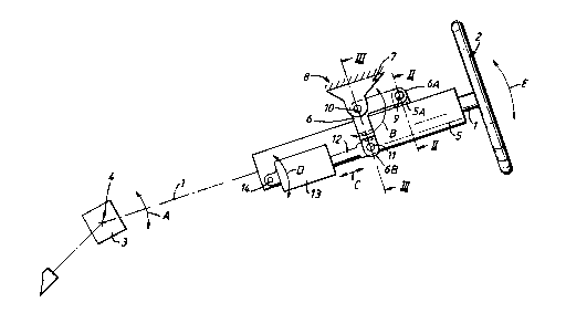
Figure 1 is a diagrammatic side view of an adjustablesteering column assembly for a vehicle comprising a
steering column incorporating a prime mover for the
. ~u.e....e of el~- ct-er~ng
/
/

WO93/09015 PCT/GB92/01906
.
- 2 - 211~923
Figure 2 is a diagrammatic sectional view taken on the line
II-II in Figure 1, and
Figure 3 is a view similar to Figure 2 taken on the line
III-III in Figure 1.
The drawing shows a vehicle steering column 1 with a
steering wheel 2 at a free end thereof. At the other end
of the major longitudinal axial extent of the steering
column 1 there is a pivotable coupling 3, which can be, for
example, in the form of a constant velocity universal
joint, another type of universal joint or a rubber
coupling. By this means, the steering column can pivot
about a pivot axis 4 in the direction indicated by the
arrows A. The steering column 1 extends through an outer
column 5, which itself is linked via a bell crank lever 6
to a steering column channel-shaped mounting bracket 7
which itself is mounted to a part 8 of the vehicle, which
part 8 is fixed relative to the steering column when fitted
for use.
One end 6A of the bell crank lever 6 is provided with a
pivot 9 about which the outer steering column 5 can pivot
via a mounting bracket 5A secured thereto. That end 6A of
the bell crank lever 6 is forked as shown in Figure 2.
The centre pivot axis of the bell crank lever 6 is provided
with a pivot 10 about which the mounting bracket 7 is
mounted. Accordingly, the lever 6 can pivot about the
pivot 10, which it does in the direction of the arrows B.
The opposite end 6B of the bell crank lever 6 is also
forked and is mounted about another pivot 11. Between the
forks is pivotably mounted one end of an arm 12 which can
reciprocate in the direction of the arrows C. The other

WO93/09015 2118 9 2 3 PCT/GB92/01906
_ - 3 -
end of the arm 12 is coupled to an electric motor 13 which
itself is mounted about a pivot 14 so that the motor can
pivot in the direction of the arrows D. The pivot 14 is
connected to the outer column 5. The motor 13 incorporates
a lead screw mechanism or gearing to convert rotary motion
to reciprocating motion for the arm 12.
It will be appreciated that operation of the motor 13
reciprocates the arm 12, thereby operating the bell crank
lever 6 which in turn raises and lowers the outer steering
column 5 and thus the main steering column 1 and this
provides vertical adjustment of the steering wheel 2 in the
direction of the arrows E.
If required, a sensor or sensors can be provided to give a
programmable capability to the electric motor drive.
The lever system provided by the present invention provides
a very rigid and robust action which enables the electric
motor to move the steering wheel satisfactorily without
unacceptable backlash, play or friction in the system.
This has advantage over known use of worm and wheel
arrangements and sliding slipper designs, which can give
excessive flexure and backlash.

Representative Drawing
A single figure which represents the drawing illustrating the invention.
Administrative Status

2024-08-01:As part of the Next Generation Patents (NGP) transition, the Canadian Patents Database (CPD) now contains a more detailed Event History, which replicates the Event Log of our new back-office solution.

Please note that "Inactive:" events refers to events no longer in use in our new back-office solution.

For a clearer understanding of the status of the application/patent presented on this page, the site Disclaimer , as well as the definitions for Patent , Event History , Maintenance Fee  and Payment History  should be consulted.

Event History

Description Date
Inactive: IPC from MCD 2006-03-11
Time Limit for Reversal Expired 1998-10-16
Letter Sent 1997-10-16
Grant by Issuance 1995-09-26
Request for Examination Requirements Determined Compliant 1994-08-10
All Requirements for Examination Determined Compliant 1994-08-10
Application Published (Open to Public Inspection) 1993-05-13

Abandonment History

There is no abandonment history.

Owners on Record

Note: Records showing the ownership history in alphabetical order.

Current Owners on Record
TORRINGTON COMPANY LIMITED (THE)
Past Owners on Record
MICHAEL THOMAS HANCOCK
Past Owners that do not appear in the "Owners on Record" listing will appear in other documentation within the application.
Documents

To view selected files, please enter reCAPTCHA code :


To view images, click a link in the Document Description column. To download the documents, select one or more checkboxes in the first column and then click the "Download Selected in PDF format (Zip Archive)" or the "Download Selected as Single PDF" button.

List of published and non-published patent-specific documents on the CPD .

If you have any difficulty accessing content, you can call the Client Service Centre at 1-866-997-1936 or send them an e-mail at CIPO Client Service Centre.


Document
Description 
Date
(yyyy-mm-dd) 
Number of pages   Size of Image (KB) 
Cover Page 1995-09-26 1 16
Abstract 1995-09-26 1 42
Description 1995-09-26 4 126
Claims 1995-09-26 1 40
Drawings 1995-09-26 1 21
Representative drawing 1998-07-21 1 8
Maintenance Fee Notice 1997-11-13 1 178
Fees 1995-09-29 1 54
Fees 1996-09-16 1 41
Fees 1994-03-11 1 45
Prosecution correspondence 1994-08-10 1 45
Prosecution correspondence 1994-11-14 2 65
Examiner Requisition 1994-09-26 1 38
PCT Correspondence 1995-07-17 1 35
Courtesy - Office Letter 1994-09-13 1 46
Courtesy - Office Letter 1994-08-31 1 59
International preliminary examination report 1994-05-11 8 235