Language selection

Search

Patent 2119338 Summary

Third-party information liability

Some of the information on this Web page has been provided by external sources. The Government of Canada is not responsible for the accuracy, reliability or currency of the information supplied by external sources. Users wishing to rely upon this information should consult directly with the source of the information. Content provided by external sources is not subject to official languages, privacy and accessibility requirements.

Claims and Abstract availability

Any discrepancies in the text and image of the Claims and Abstract are due to differing posting times. Text of the Claims and Abstract are posted:

  • At the time the application is open to public inspection;
  • At the time of issue of the patent (grant).
(12) Patent: (11) CA 2119338
(54) English Title: SELECTIVE MUSCLE EXERCISER
(54) French Title: EXERCISEUR POUR MUSCLE SPECIFIQUE
Status: Expired and beyond the Period of Reversal
Bibliographic Data
(51) International Patent Classification (IPC):
  • A63B 21/065 (2006.01)
(72) Inventors :
  • WINSTON, EDITH (United States of America)
(73) Owners :
  • EDITH WINSTON
(71) Applicants :
  • EDITH WINSTON (United States of America)
(74) Agent: BORDEN LADNER GERVAIS LLP
(74) Associate agent:
(45) Issued: 1999-12-14
(22) Filed Date: 1994-03-17
(41) Open to Public Inspection: 1995-05-13
Examination requested: 1995-11-20
Availability of licence: N/A
Dedicated to the Public: N/A
(25) Language of filing: English

Patent Cooperation Treaty (PCT): No

(30) Application Priority Data: None

Abstracts

English Abstract

An exercising device with side-by-side external weights that are movable relative to each other so as to permit the device to assume a circular curvature in encircling relation about a limb of the user, this assumed curvature being used to advantage to position the device in overlying relation to a selected specific muscle for development of that muscle rather than for merely gross limb motion exercises as now results from a wrist, ankle or waist location.


French Abstract

Un dispositif d'exercice avec des poids externes côte à côte qui sont mobiles l'un par rapport à l'autre afin de permettre à l'appareil d'assumer une courbure circulaire dans une relation encerclant un membre de l'utilisateur, cette courbure étant mise à profit pour positionner l'appareil dans une relation recouvrant un muscle spécifique sélectionné pour le développement de ce muscle plutôt que pour les exercices grossiers de mouvement du membre tels que ceux résultant d'un placement sur les poignets, les chevilles ou la taille.

Claims

Note: Claims are shown in the official language in which they were submitted.

CLAIMS:
1. A generally circular shape-assuming exercising device for selective
positioning
on a user in encircling relation about a limb of said user comprising a body
having an
exterior ply means bounding plural gussets therealong for receiving individual
weights
sized to have an operative inserted position in each said gusset in side by
side relation to
each other and on an exterior side of said body such that adjacent weights are
adapted to
partake of relative movement resulting in a circular configuration, flap means
of neoprene
construction material having an operative folded condition against an interior
side of said
body so as to have an interposed position between said weights and said user
to contribute
to comfort in the wearing use of said exercising device, and a band of
neoprene
construction material extending laterally of said body having an operative
position in
encircling relation about a limb of said user, said laterally extending band
being of a
dimension long enough that in a stretched condition there is formed at least
one closed loop
thereof about said limb, whereby said encircling position is effective in
applying the
weights for the exercising of muscles located at said position.
8

Description

Note: Descriptions are shown in the official language in which they were submitted.


2119338
Selective Muscle Exerciser
The present invention relates generally to improvements for
plural weight-embodied exercising devices, the improvements, more
particularly, enabling advantageous use of the exercising device
for specific muscle development, as results from the direct appli-
cation on the user to specific muscle locations such as, by way of
example, the biceps, triceps, quadriceps, hamstrings, to mention
but a few.
Examples of the Prior Art
Weights are useful~in exercise routines, a common example
being the use of hand-gripped dumbbells for arm and upper torso
exercises. Instead of hand-gripped weights, there is also common
use of wrist weights, using one or more inserted weight bars, as
exemplified by the "wrist weight" of my prior patent U.S. Des. 339,838
issued on September 28, 1993 which, in use, as best shown in Fig.
2, is worn in encircling relation about the wrist. Whether hand-
gripped or conveniently worn on a wrist, an ankle, or even around
the waist, the benefits of the exercise are not advantageously
applied to specific muscle development, but rather mass development
of a limb. Stated otherwise, the location of the exercising weight
is selected more for gross motion and convenience in the fitting of
the exercising device to the user, rather than in biceps, triceps,
quadriceps, hamstring or other specific muscle development.
Broadly, it is an object of the present invention to provide
an exercising device overcoming the foregoing and other shortcom-
ings of the prior art. More particularly, it is an -object to

s'
2119338
enable the device to be used in overlying position to a specific
muscle, and not be necessarily limited to gross limb motion as
results from a wrist, ankle or waist location.
The description of the invention which follows, together with
the accompanying drawings should not be construed as limiting the
invention to the examples shown and described, because those
skilled in the art to which this invention appertains will be able
to devise other forms thereof within the ambit of the appended
claims.
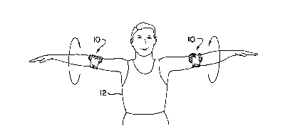
Fig. 1 is a perspective view of the within inventive device
being used for arm exercises;
Fig. 2 is an exploded view of the device of Fig. 1 better
illustrating the component parts thereof;
Figs. 3 and 4 are assembled views of the exercising device in
plan and bottom perspectives respectively;
Fig. 5 is an enlarged scale side elevational view in cross
section taken along line 5-5 of Fig. 3;
Fig. 6 is a view similar to Fig. 1, but of the within inven-
tive device being used for leg exercises;
Fig. 7 is an exploded view similar to Fig. 2, but of the
larger-sized device of Fig. 6;
Figs. 8 and 9 are views of said larger-sized device similar to
Figs. 3 and 4; and
Fig. 10 is an enlarged scale side elevational view in cross
section taken along line 10-10 of Fig. 8.
Underlying the present invention is the use of an exercising
2

. . ~ 21 19338
device embodying a select number of weights and applied specific-
ally for development of specific muscles, thereby serving function-
ally as a brachialis weight 10 in Fig. 1 and a rectus femoris
weight 110 in Fig. 6 as used by the exerciser 12 in these figures.
Structurally, the exercising weights 10 and 110 are very similar,
being only sized appropriately to be worn in encircling relation
about the arm and leg locations in overlying relation to specific
selected muscles, as already enumerated by way of example, of the
user 12.
Referring to the brachialis exercise routine as shown in Fig.
1, the within inventive device 10, worn about the upper arm just
above the elbow, is used in a variety of exercise routines to
develop the noted muscle. When device 10 is in use, the weight
pocket assembly 14 is held in place by an attached elastic neoprene
strap section 16. Strap section 16 is comprised of a Velcro hook
patch 18 and a stretchable neoprene strip 20.
Pocket assembly 14 is made with a rectangular body panel 22 of
fabric-covered foam which has a weight-inserting opening 24 and
four angularly cropped corners 26. On the outside of panel 22 a
plural gusset-forming fabric panel 28 is top stitched at spaced
intervals 30, as best seen in Fig. 3, to form pockets or compart-
ments 32 to receive in inserted operative positions cooperating
weights 36. The bottom edge 34 of panel 28 is folded before
stitching, as best seen in Fig. 5, to thus provide a double thick-
ness reinforcement against rupture as might be caused by the
weights 36 at the lower end of each pocket 32.
3

2119338
For both devices 14 and 110 the respectively used individual
weights 36 and 136 are preferably of one half pound and sized
appropriately for embodiment in the devices. In Figs. 1-5, each
pocket 32 is sized so as to be adapted to receive a single weight
36, but a double sized or gusset pocket 132 could also be used as
with the rectus femoris exerciser 110 of Figs. 6-10.
It is to be noted that on the outside of panel 22 are appro-
priately stitched or adhesively secured Velcro loop swatches 38
which cooperate with Velcro hook patch 18 to form a closed loop of
the device 10. Another Velcro hook patch 40 is included within
piping 42 at the lower edge of panel 22, and is used to hold in
place a flap assembly 44 which also is included within piping 42
when the upper edge of panel 22 is sewn. Flap assembly 44 is used
both as a closure over panel opening 24 to retain the weights 36
within the pockets 32 and also, by virtue of its interposed posi-
tion, as a cushioning pad between the weights 36 and the user's
arm. To this end, flap 44 consists of an inner layer 46 of fabric
covered foam, a middle layer 48 of heavier denier material of
appropriate construction material to strengthen the flap and
provide backing to foam sandwiched between it and outer layer 50
which is a composite rubber neoprene with a velvet underside.
Layers 46, 48 and 50 are attached along the bottom and side edges
with piping 52 to form a composite flap 44 foldable along one side.
Layer 46 will be understood to have the characteristic of adhering
readily to Velcro hook material 40 and layer 50 to have a non-slip
characteristic.
4

. . ~ 21 19338
In use, the weight pocket section 14 with the weights 36 in an
external position is placed over the upper arm of the user 12 and
strap section 16 brought around and pulled tight and secured by
Velcro patch 18 against either of the Velcro patches 38 depending
on the arm size of the user. It is significant at this point to
note that generally the shape assumed by the device 10 is corres-
pondingly circular and thus conforms to the shape of a limb,
whether an arm or leg, and this thus readily permits the device 10,
as well as device 110, to be selectively applied for exercising use
to a limb muscle. The assumed circular shape is in turn a result
of the use of plural side by side gussets, individually and collec-
tively designated 28, allowing relative movement at the attaching
seams 30 between adjacent weights 36. Stated otherwise, adjacent
weights 36 progressively assume positions of contact against the
user's circular arm, or leg as the case may be, and thus are of an
arcuate or generally circular shape conforming to the underlying
limb shape on which the exercising device 10 is positioned.
Referring now to device 110, this device is shown worn about
the upper leg just above the knee, preparatory to exercising the
rectus femoris, and is, of course, movable to an overlying position
to exercise other muscles incident to being used in a variety of
exercise routines to develop the legs and lower body as shown in
Fig. 6.
Device 110 has a weight pocket assembly section 112 held in
position by an attached elastic strap section 114. Section 114 is
comprised of a Velcro hook patch 116 and an elastic neoprene strip

. ~ 21 19338
118 which is combined with a similarly sized elastic strip of
velvet neoprene 120.
Pocket assembly 128 consists of a rectangular body panel 122
made of fabric covered foam which has a weight-inserting opening
124 and four angularly cropped corners 126. To the outside of
panel 122 a "corrugated" gusset-forming fabric panel 128 is
stitched as at 130, as best seen in Fig. 8, to form in this in-
stance plural increased double weight-receiving gusset pockets 132.
The bottom edge 134 of panel 128 is folded before stitching, as
seen best in Fig. 10, to provide a reinforcement against rupture as
might be caused by the weights 136 at the lower end of each weight
pocket 132.
As with the construction previously described with respect to
panel 22, on the outside of panel 122 use is made of adhered Velcro
loop swatches 138 to cooperate with the Velcro hook patch 116 in
looping device 110 about the user's thigh. Another section of
Velcro hook material 140 is included within piping 142 at the lower
edge of panel 122 during the sewing finishing steps. Velcro hook
patch 140 is used to hold against body panel 122 the flap assembly
144 which is included within piping 142 when the upper edge of
panel 122 is sewn. Flap assembly 144, like its counterpart flap
44, is used to retain weights 136 within the pockets 132 and also
act as a cushioning pad between the weights 136 and the user's leg.
Flap 144 consists of a layer 146 of a fabric-covered foam, a layer
148 sandwiched between layer 146 and layer 150 which is a composite
rubber neoprene with a velvet underside. Layers 146, 148 and 150
6

2119338
are attached along the bottom and side edges of piping 152 to form
a composite unit 144.
In use, the weight pocket section 112 is placed generally
above the user's knee in overlying relation to a specific muscle to
be exercised and strap section 114 is brought around and pulled
taut by being secured using the Velcro patch 116 against either of
the Velcro patches 138.
While the different sized exercise devices 10 and l10 having
specific application for development of specific muscles herein
shown and disclosed in detail are fully capable of attaining the
objects and providing the advantages hereinbefore stated, it is to
be understood that they are merely illustrative of the presently
preferred embodiments of the invention and that no limitations are
intended to the detail of construction or design herein shown other
than as defined in the appended claims.
7

Representative Drawing
A single figure which represents the drawing illustrating the invention.
Administrative Status

2024-08-01:As part of the Next Generation Patents (NGP) transition, the Canadian Patents Database (CPD) now contains a more detailed Event History, which replicates the Event Log of our new back-office solution.

Please note that "Inactive:" events refers to events no longer in use in our new back-office solution.

For a clearer understanding of the status of the application/patent presented on this page, the site Disclaimer , as well as the definitions for Patent , Event History , Maintenance Fee  and Payment History  should be consulted.

Event History

Description Date
Time Limit for Reversal Expired 2014-03-18
Letter Sent 2013-03-18
Grant by Issuance 1999-12-14
Inactive: Cover page published 1999-12-13
Inactive: Final fee received 1999-09-09
Small Entity Declaration Determined Compliant 1999-09-09
Pre-grant 1999-09-09
Notice of Allowance is Issued 1999-06-04
Letter Sent 1999-06-04
Inactive: Cover page published 1999-06-01
Inactive: Adhoc Request Documented 1999-06-01
Inactive: Prior art correction 1999-06-01
Inactive: Status info is complete as of Log entry date 1999-06-01
Inactive: Application prosecuted on TS as of Log entry date 1999-06-01
Inactive: Approved for allowance (AFA) 1999-05-11
Request for Examination Requirements Determined Compliant 1995-11-20
All Requirements for Examination Determined Compliant 1995-11-20
Application Published (Open to Public Inspection) 1995-05-13

Abandonment History

There is no abandonment history.

Maintenance Fee

The last payment was received on 1999-02-23

Note : If the full payment has not been received on or before the date indicated, a further fee may be required which may be one of the following

  • the reinstatement fee;
  • the late payment fee; or
  • additional fee to reverse deemed expiry.

Please refer to the CIPO Patent Fees web page to see all current fee amounts.

Fee History

Fee Type Anniversary Year Due Date Paid Date
MF (application, 4th anniv.) - small 04 1998-03-17 1998-01-28
MF (application, 5th anniv.) - small 05 1999-03-17 1999-02-23
Final fee - small 1999-09-09
MF (patent, 6th anniv.) - small 2000-03-17 2000-02-22
MF (patent, 7th anniv.) - small 2001-03-19 2001-02-21
MF (patent, 8th anniv.) - small 2002-03-18 2002-01-22
MF (patent, 9th anniv.) - small 2003-03-17 2003-02-20
MF (patent, 10th anniv.) - small 2004-03-17 2004-01-30
MF (patent, 11th anniv.) - small 2005-03-17 2005-02-02
MF (patent, 12th anniv.) - small 2006-03-17 2006-03-07
MF (patent, 13th anniv.) - small 2007-03-19 2007-02-06
MF (patent, 14th anniv.) - small 2008-03-17 2008-01-28
MF (patent, 15th anniv.) - standard 2009-03-17 2009-02-24
MF (patent, 16th anniv.) - standard 2010-03-17 2010-01-26
MF (patent, 17th anniv.) - standard 2011-03-17 2011-03-02
MF (patent, 18th anniv.) - standard 2012-03-19 2012-02-28
Owners on Record

Note: Records showing the ownership history in alphabetical order.

Current Owners on Record
EDITH WINSTON
Past Owners on Record
None
Past Owners that do not appear in the "Owners on Record" listing will appear in other documentation within the application.
Documents

To view selected files, please enter reCAPTCHA code :


To view images, click a link in the Document Description column. To download the documents, select one or more checkboxes in the first column and then click the "Download Selected in PDF format (Zip Archive)" or the "Download Selected as Single PDF" button.

List of published and non-published patent-specific documents on the CPD .

If you have any difficulty accessing content, you can call the Client Service Centre at 1-866-997-1936 or send them an e-mail at CIPO Client Service Centre.


Document
Description 
Date
(yyyy-mm-dd) 
Number of pages   Size of Image (KB) 
Representative drawing 1998-05-21 1 5
Representative drawing 1999-12-06 1 4
Abstract 1995-10-28 1 52
Cover Page 1995-10-28 1 62
Description 1995-10-28 7 389
Claims 1995-10-28 1 49
Drawings 1995-10-28 4 229
Description 1999-04-28 7 269
Claims 1999-04-28 1 30
Cover Page 1999-12-06 1 24
Commissioner's Notice - Application Found Allowable 1999-06-04 1 165
Maintenance Fee Notice 2013-04-29 1 171
Correspondence 1999-09-09 1 30
Fees 1997-03-03 1 39
Fees 1996-03-06 1 39
Prosecution correspondence 1995-11-20 1 23
Prosecution correspondence 1999-03-25 3 86
Examiner Requisition 1999-01-14 2 50
Prosecution correspondence 1998-10-29 1 29
Examiner Requisition 1998-05-29 1 27
Prosecution correspondence 1998-04-09 3 89
Examiner Requisition 1998-01-30 1 31
Prosecution correspondence 1996-03-11 2 29
Prosecution correspondence 1996-09-30 1 27
Courtesy - Office Letter 1995-12-06 1 49
Prosecution correspondence 1994-03-17 5 197