Language selection

Search

Patent 2119347 Summary

Third-party information liability

Some of the information on this Web page has been provided by external sources. The Government of Canada is not responsible for the accuracy, reliability or currency of the information supplied by external sources. Users wishing to rely upon this information should consult directly with the source of the information. Content provided by external sources is not subject to official languages, privacy and accessibility requirements.

Claims and Abstract availability

Any discrepancies in the text and image of the Claims and Abstract are due to differing posting times. Text of the Claims and Abstract are posted:

  • At the time the application is open to public inspection;
  • At the time of issue of the patent (grant).
(12) Patent Application: (11) CA 2119347
(54) English Title: TOOL BIT RETAINING ASSEMBLY
(54) French Title: DISPOSITIF DE RETENUE POUR OUTIL
Status: Deemed Abandoned and Beyond the Period of Reinstatement - Pending Response to Notice of Disregarded Communication
Bibliographic Data
(51) International Patent Classification (IPC):
  • B25B 15/00 (2006.01)
  • B25B 15/02 (2006.01)
  • B25B 23/00 (2006.01)
(72) Inventors :
  • MARKWART, RONALD (Canada)
  • MARKWART, LESLIE (Canada)
(73) Owners :
  • INNO-WARE ENTERPRISES LIMITED
(71) Applicants :
  • INNO-WARE ENTERPRISES LIMITED (Canada)
(74) Agent: NEXUS LAW GROUP LLP
(74) Associate agent:
(45) Issued:
(22) Filed Date: 1994-03-17
(41) Open to Public Inspection: 1994-09-18
Availability of licence: N/A
Dedicated to the Public: N/A
(25) Language of filing: English

Patent Cooperation Treaty (PCT): No

(30) Application Priority Data:
Application No. Country/Territory Date
08/032,495 (United States of America) 1993-03-17

Abstracts

English Abstract


ABSTRACT
A tool bit retaining assembly for a tool of a type
having a tool bit receptacle and a spring receiving region with
a hole opening into the receptacle and a tool bit insertable into
the receptacle. The tool bit has a transverse groove proximate
an insertion end thereof, and includes a ball bearing with a
diameter only slightly larger than that of the hole such that
upon being pressed against the hole the ball bearing extends
through the hole into the receptacle and engages the transverse
groove in said tool bit. A split ring spring having a split
extending from one end to the other with a portion transverse to
the axis thereof is positionable around said spring receiving
region such that the transverse portion of the split is opposite
the ball bearing. The spring also has a hole on a side opposite
the split of a diameter smaller than that of the ball bearing,
such that with the hole in the spring against the ball bearing,
the latter is pressed against the hole in the tool and engages
a tool bit groove of a tool bit positioned in the receptacle.


Claims

Note: Claims are shown in the official language in which they were submitted.

- 6 -
I CLAIM:
1. A tool bit retaining assembly for a tool of a type having
a tool bit receptacle and a spring receiving region with a hole
opening into the receptacle and a tool bit insertable into
receptacle and the tool bit having a transverse groove proximate
an insertion end thereof, comprising:
(a) a ball bearing having a diameter only slightly larger
than that of the hole such that upon being pressed against the
hole the ball bearing extends through the hole into the
receptacle and engages the transverse groove in said tool bit;
(b) a split ring spring having a split extending from one
end to the other with a portion substantially transverse to the
axis thereof and positionable around said spring receiving region
such that the transverse portion of the split is opposite the
ball bearing, said spring also having a hole on a side opposite
the split of a diameter smaller than that of the ball bearing,
such that with the hole in the spring against the ball bearing,
the latter is pressed against the hole in the tool and engages
a tool bit groove of a tool bit positioned in the receptacle.
2. An assembly according to claim 1, such that the split has
the transverse portion midway along the length of said spring.
3. An assembly according to claim 1, including a handle, a
nosepiece inserted into said handle, with the tool bit receptacle
located in an end of said nosepiece, and the spring receiving
region located on the nosepiece proximate a distal end thereof.
4. An assembly according to claim 3 wherein a surface of the
spring receiving region is roughened with tiny sharp protrusions

- 7 -
so as to impede said spring from turning around a surface of said
region.
5. A tool having a tool bit receptacle, comprising:
(a) a spring receiving region on said tool having a hole
opening into the receptacle;
(b) a tool bit insertable into the tool bit receptacle and
having a substantially transverse groove near an insertion end
thereof;
(c) a ball bearing having a diameter only slightly larger
than the hole such that upon being pressed against the hole the
ball bearing extends through the hole into the receptacle and
engages the transverse groove in said tool bit;
(d) a split ring spring having a split extending from one
end to the other with a portion transverse to the axis thereof
and positionable around said spring receiving region such that
the transverse portion of the split is opposite the ball bearing,
said spring also having a spring hole on a side opposite the
split of a diameter smaller than that of the ball bearing, such
that with the spring hole in the spring against the ball bearing,
the latter is pressed against the hole in the tool and engages
a tool bit groove of a tool bit positioned in the receptacle.
6. A tool according to claim 5, wherein said spring
receiving region has a roughened surface to restrain said spring
from turning.
7. A tool according to claim 6, wherein the transverse
portion of the split is midway along the length of said spring.
8. A tool according to claim 5, including a handle and a

- 8 -
nosepiece inserted into said handle and said receiving region is
a region of slightly narrower cross sectional dimensions than a
surrounding region of said nosepiece.
9. A tool having a handle, a nosepiece inserted into said
handle and a tool bit receptacle in an end of said nosepiece,
comprising:
(a) a spring receiving region on said nosepiece having a
nosepiece hole opening into the receptacle;
(b) a tool bit insertable into the tool bit receptacle and
having a transverse groove near an insertion end thereof;
(c) a ball bearing having a diameter only slightly larger
than the nosepiece hole such that upon being pressed against the
nosepiece hole the ball bearing extends through the nosepiece
hole into the receptacle and engages the transverse groove in
said tool bit;
(d) a split ring spring having a split extending from one
end to the other with a portion substantially transverse to the
axis thereof and positionable around said spring receiving region
such that the transverse portion of the split is opposite the
ball bearing, said spring also having a spring hole on a side
opposite the split of a diameter smaller than that of the ball
bearing, such that with the spring hole against the ball bearing,
the latter is pressed against the nosepiece hole in the tool and
engages a tool bit groove of a tool bit positioned in the
receptacle.
10. A tool according to claim 9, wherein said spring
receiving region has a cylindrical outer surface of slightly
smaller diameter than the width of the remainder of the nosepiece

- 9 -
and the outer surface of said region is roughened to impede any
tendency of the spring to turn.
11. A tool according to claim 10, wherein said transverse
portion of the split is midway along the length of said spring
and aligned transversely with the spring hole.
12. A tool according to claim 9, wherein said spring split
includes a longitudinally extending split on either end of said
spring joining opposite ends of the transverse portion of the
spring.

Description

Note: Descriptions are shown in the official language in which they were submitted.


- TOOL BIT RETAINING ASSEMBLY 2 ~ 4 7
BACRGRO~lND
: .
The present invention relates to an assembly for
retaining a removable tool bit in place while at the same time
allowing it to be manually removed against a biasing force
applied to the tool bit by the assembly.
Removable tool bit assemblies must be capable of
accommodating rapid insertion and removal of the tool bit without ,-
the need for screwing and unscrewing locking assemblies or
imparting any other time consuming operation in order to retain
and remove the tool bit. One solution as disclosed by U.S.
Patent 4,924,733 is to use a magnet in ths nosepiece abutting an
end of the tool bit when inserted. However, the magnet
constitutes and additional expense and assembly step to install.
Moreover, magnets can 106e their strength and become ineffective,
particularly when the make contact only with the pointed end of ~ ;-
the bit.
Another common arrangement, is a receptacle in a shaft
or nose piece into which the bit is ins~rted until a notch in the
tool aligns with a hole in the shaft. A ball bearing slightly
larger than the hole in the shaft is held against the hole and
extends through the latte'r to engage the notch by a spring that
is held against the ball bearing. The spring is in the form of
a split ring with a hole opposite the split so as to impede
movement of the ring relative to the ball. One problem with such
a device is that the ring often slips off of the ball bearing and
turns to the degree that the split straddles the ball bearing.
At the latter point it is often the case that the ball will
squeeze through the split, drop to the ground and become lost.
The screwdriver thus becomes inoperative.
: ~
Accordingly, it is an object of the invention to
provide an improved assembly for releasably holding a tool bit
in place.
,, ~,,

, - 2 - 211~47
~MaRY OF THE ll~VENTION
According to the invention there is provided a tool bit
retaining assembly for a tool of a type having a tool bit
receptacle and a spring receiving region with a hole opening into
the receptacle and a tool bit insertable into the receptacle.
The tool bit has a transverse groove proximate an insertion f~nd
therèof, and incl~des a ball bearing with a diameter only
slightly larger than that of the hole such that upon being
pressed against the hole the ball bfearing extends through the
hole into the receptacle and engages the transverse groove in
said tool bit. A split ring spring having a split extending from
one end to the other with a portion substantially transverse to
the axis thereof is positionable around said spring receiving
region such that the transverse portion of the split is opposite
the ball bearing. The spring also has a hole on a side opposite
the split of a diameter smaller than that of the ball bearing,
such that with the hole in the-spring ayainst the ball bearing,
the latter is pressed against the hole in the tool and engages
a tool bit groove of a tool bit positioned in the receptacle.
i
I Preferably the split has the transverse portion midway
I along the length of said spring. P~lvantageously, the tool
includes a handle, a nosepiece inserted into the handle, with
the toofl bit receptacle located in an end of said nosepiece. The
spring receiving region may be located on the nosepiece proximate
f a distal end thereof.
.
The transverse portion of the split may be midway along
the length of said spring. Moreover, a surface of the spring
receiving region may be roughened with tiny sharp protrusions so
f as to impede said spring from turning around a surface of the
I region.
.
, ?
i ;~
':`',. ;'.,: ,, " . . ' ` : . . '

_ 3 _ 2~3~7
BRIEF DESiCRIPTIO~ OF T~E DRAWINGS :
The novel features believed charactexistic of the
invention are set forth in the appended claims. The invention
itself, however, as well as other features and advantages : ~:~
thereof, will be best unders~ood by reference to the detailed ~:
description which follows, read in conjunction with the
accompanying drawings, wherein:
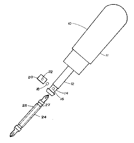
Figure 1 is an elevation view of a screwdriver with the
tool bit and tool bit retainer assembly exploded;
l Figure 2 is an end view of the nosepiece end of the
-' screwdriver;
.~J Figure 3 is a partial sectional view of the nosepiece
.~ of the screwdriver;
.
~1
.i~ Figure 4 is a perspective view of a conventional
retainer spring;
Figure 5 is a perspective view of the opposite side o~
the retainer spring shown in Figure 4;
:~ Figure 6 is a perspective view of a preferred
.~ embodiment of the spring of the present invention; and
Figure 7 is a perspective view of the opposite side of
the spring shown in Figure 6.
.`.. 'i DEq~AILED DE~;CRIPTION WITH REFE~RENCE TO THE DR~WINGS :
'
Referring to Figure 1 there is shown a screwdriver 10
'i"31 having a handle 11 into one end of which is affixed a nosepiece
12. The nosepiece 12 has a recessed portion 14 of narrower
diameter near the end thereof. As shown in Figure 2, a hexagonal ~ ;
~! :
... ~

2 ~
receptacle 34 is formed in the nosepiece for receiving a tool bit
24 having a hexagonal shank 25. The tool bit 24 has a transverse
groove 27 near an end thereof. The recessed portion 14 has a
roughened surface and a hole 16 opening into the receptacle 34.
A ball bearing 18 is dimensioned to fit into the hole 16 and when
pressed against the latter extends into recepta~le 34 ~nd engages
groove 27. Spring 20 has a hole 22 smaller in diameter than the
ball bearing ~8. With the spring fitted over the recess 14 with
hole 22 aligned with the ball bearing 18 and the latter
positioned against hole 16, the tool bit 24 when inserted is held
in place by the spring pressure against the ball bearing 18.
A more detailed view of the positioning of the spring
20, the ball bearing 18 vis-a~vis the nosepiece 12 is seen in
Figure 3.
Figures 4 and 5 show a conventional split ring spring
26 having a split 28 parallel to an axis of the spring 26 and a
hole 30 on an opposite side of the split 28. In this case if the
hole 30 slips away from the ball bearing 18 it will shift until
split 28 aligns with the ball bearing ~8. At that point the
pressure of the spring against the ball bearing will cause the
split to widen and permit the ball bearing 18 to fall out.
Figures 6 and 7 show a preferred embodiment of the
spring in accordance with the present invention. The split 32
in this case has a serpentine shape with a transverse portion 33
along the centre joining two ganerally vertical portions 35 and
37. In this case if the spring were to shift so that hole 22
slid past ball bearing 18 even if the transverse portion 33 of
the split were to align against the ball bearing, the space
between the edges of the transverse portion 33 of the split would
not widen. They would merely move parallel and in opposite
directions to each other. Thus, the ball bearing would not fall
out.
,~ ;.. ,. ,~ . , . ............. ,, : ,
if.. ~. ` . 1, ~. ,." : ; . i . , ', ',, . ,, . ' ~" , ' , :
~'~ ' ' ' . : ' ' . . : ' ' ' : ' ': . ' ; ' : : , . ', .,

- 2~1~3~7 ;:
Accordingly, while this invention has been described
with reference to illustrative embodiments, this description is
not intended to be construed in a limiting sense. Various
modifications of the illustrative embodiments, as well as other
embodiments of the invention, will be apparent to persons s~illed
in the art upon reference to this description. It is therefore
contemplated that the appended claims will cover any such
modification or embodiments as fall within the true scope of the
invention.
,
. .: .
,..
:
,
.?~ i. . .. , ' .,. "~, ,j ","~, . ,, . " "" , ,~,,";" , ~ " ", ;

Representative Drawing
A single figure which represents the drawing illustrating the invention.
Administrative Status

2024-08-01:As part of the Next Generation Patents (NGP) transition, the Canadian Patents Database (CPD) now contains a more detailed Event History, which replicates the Event Log of our new back-office solution.

Please note that "Inactive:" events refers to events no longer in use in our new back-office solution.

For a clearer understanding of the status of the application/patent presented on this page, the site Disclaimer , as well as the definitions for Patent , Event History , Maintenance Fee  and Payment History  should be consulted.

Event History

Description Date
Inactive: Agents merged 2011-07-06
Inactive: IPC from MCD 2006-03-11
Time Limit for Reversal Expired 1996-09-17
Application Not Reinstated by Deadline 1996-09-17
Deemed Abandoned - Failure to Respond to Maintenance Fee Notice 1996-03-18
Inactive: Adhoc Request Documented 1996-03-18
Application Published (Open to Public Inspection) 1994-09-18

Abandonment History

Abandonment Date Reason Reinstatement Date
1996-03-18
Owners on Record

Note: Records showing the ownership history in alphabetical order.

Current Owners on Record
INNO-WARE ENTERPRISES LIMITED
Past Owners on Record
LESLIE MARKWART
RONALD MARKWART
Past Owners that do not appear in the "Owners on Record" listing will appear in other documentation within the application.
Documents

To view selected files, please enter reCAPTCHA code :


To view images, click a link in the Document Description column. To download the documents, select one or more checkboxes in the first column and then click the "Download Selected in PDF format (Zip Archive)" or the "Download Selected as Single PDF" button.

List of published and non-published patent-specific documents on the CPD .

If you have any difficulty accessing content, you can call the Client Service Centre at 1-866-997-1936 or send them an e-mail at CIPO Client Service Centre.


Document
Description 
Date
(yyyy-mm-dd) 
Number of pages   Size of Image (KB) 
Drawings 1994-09-18 3 172
Cover Page 1994-09-18 1 92
Abstract 1994-09-18 1 73
Claims 1994-09-18 4 269
Descriptions 1994-09-18 5 316
Representative drawing 1998-08-17 1 8
PCT Correspondence 1995-03-15 1 30
Courtesy - Office Letter 1994-11-17 1 25
Prosecution correspondence 1994-11-02 2 68