Language selection

Search

Patent 2119439 Summary

Third-party information liability

Some of the information on this Web page has been provided by external sources. The Government of Canada is not responsible for the accuracy, reliability or currency of the information supplied by external sources. Users wishing to rely upon this information should consult directly with the source of the information. Content provided by external sources is not subject to official languages, privacy and accessibility requirements.

Claims and Abstract availability

Any discrepancies in the text and image of the Claims and Abstract are due to differing posting times. Text of the Claims and Abstract are posted:

  • At the time the application is open to public inspection;
  • At the time of issue of the patent (grant).
(12) Patent: (11) CA 2119439
(54) English Title: RETRUDER
(54) French Title: EXTRUDEUSE BIDIRECTIONNELLE
Status: Expired and beyond the Period of Reversal
Bibliographic Data
(51) International Patent Classification (IPC):
  • B29B 7/48 (2006.01)
(72) Inventors :
  • ZIMMERMANN, ANTON (Switzerland)
(73) Owners :
  • ANTOGI AG
(71) Applicants :
  • ANTOGI AG (Switzerland)
(74) Agent: BORDEN LADNER GERVAIS LLP
(74) Associate agent:
(45) Issued: 2000-06-06
(86) PCT Filing Date: 1993-07-23
(87) Open to Public Inspection: 1994-02-03
Examination requested: 1996-06-27
Availability of licence: N/A
Dedicated to the Public: N/A
(25) Language of filing: English

Patent Cooperation Treaty (PCT): Yes
(86) PCT Filing Number: PCT/CH1993/000186
(87) International Publication Number: WO 1994002303
(85) National Entry: 1994-03-18

(30) Application Priority Data:
Application No. Country/Territory Date
02321/92-7 (Switzerland) 1992-07-23

Abstracts

English Abstract


A retruder (re-verse ex-truder) is provided herein. The retruder is for the
continuous mixing and kneading of media under increased pressure and includes
a drive,
at least one casing, and at least two counterrotating intermeshing reversing
screws. Such
reversing screws move the medium in the conveying direction and in the reverse
direction. In this way, the medium is transported from a loading point to a
discharge
point of the casing, which is disposed vertically to the conveying direction.


Claims

Note: Claims are shown in the official language in which they were submitted.

Claims
1. A retruder comprising:
a housing having an inlet port for receiving material being processed and an
outlet
port for discharging material spaced from the inlet port along the length of
the housing;
a pair of elongated screws in said housing for rotating in opposite
directions;
each said screw having a helical thread thereon and running in opposite
directions
from a point along the respective screw, said threads mutually meshing and
conveying
material being passed from the inlet along the length of the screws toward the
outlet and
then in a reverse direction back toward the inlet.
2. Retruder for the continuous mixing and kneading of media under increased
pressure comprising:
a drive;
at least one casing; and
at least two counter-rotatable intermeshing reversing screws for moving said
medium in the conveying direction and in the reverse direction, such that said
medium
is transported from a loading point to a discharge point of said casing, which
is disposed
vertically to the conveying direction.
3. Retruder according to claim 1 or claim 2, wherein the pitch of the thread
of a screw increases and decreases progressively along the length of the screw
in
dependence on the direction of conveying of the material.
4. Retruder according to claim 1, claim 2 or claim 3, wherein each of said
screws is made in one piece as a monobloc.
5. Retruder according to claims 1 to 4, wherein the pitch of the thread of
each of said screws is different in the direction of conveying of material and
in the
reverse direction.
6. Retruder according to claims 1 to 5, wherein said reversible screws are
mounted at only one end of said housing or casing.
7. Retruder according to claims 1 to 5, wherein said reversible screws are
mounted at each end of said housing or casing.

7
8. Retruder according to claims 1 to 7, wherein the depth of a channel
between the outer edge and the root of the threads of said reversible screws
tapers off
in the respective direction of material conveying.
9. Retruder according to claims 1 to 8, wherein said housing or said casing
has at least one cooling jacket.
10. Retruder according to claims 1 to 8, wherein said housing or said casing
has at least one heating jacket.
11. A retruder as in claims 1 to 10, wherein said housing or said casing
outlet
port is generally transverse to the longitudinal axes of the screws.
12. Retruder according to claims 1 to 11, further comprising a
continuously-variable drive for said screws.

Description

Note: Descriptions are shown in the official language in which they were submitted.


,x.21 1 94 39
1
(a) TITLE OF THE INVENTION
RETRUDER
(b) TECHNICAL FIELD TO WHICH THE INVENTION BELONGS
The invention relates to a retruder, i.e., a reverse extruder for continuously
conveying, mixing and/or kneading media at elevated pressure. The term
"extruder" has
become established for apparatus of a similar type. Since this term is
fundamentally
incorrect for the present invention, because of the reversal of the direction
of conveying,
instead of a circumlocution the abbreviation retruder (re-verse ex-truder) is
used herein.
(c) BACKGROUND ART
Continuous conveying, mixing and/or kneading of media is part of the basic
operations of process engineering. The material for mixing and/or conveying
can be
very different substances. The chemical and physical properties of these
substances, their
state of aggregation and their behaviour under pressure and heat can be
correspondingly
different. The solutions provided by the chemical engineering of the prior
art, which
extend from kneading chocolate compositions, producing semifinished plastics
by
extrusion and processing flowable plastics granules with a glass fibre content
for injection
moulding, to the disposal of biologically active waste, correspond to this
variety. For
all these tasks there are known machines which have, depending on the
requirements,
cooled or heated housings and at least two rotating, mutually meshing
conveying screws
which produce a pressure build-up by forcibly conveying the medium in the
individual,
closes windings of the screw channel, without having a reactive effect on the
mass
transport. The seals and the bearings are the weak points of these
constructions, since
the conveying pressure produces high axial pressures. In particular, this
disadvantage
becomes important when processing abrasive media, or when the high pressures
in the
medium for the purpose of increasing the frictional forces in the medium are
themselves
advantageous. This is the case with kneading tasks if the efficiency of
kneading is
increased or, for example, in the case of a frictional reactor which is to be
operated as
a thermo-mechanical process unit for preparing biomass, at high operation
pressures.

21 1 94 39
2
(d) DESCRIPTION OF THE INVENTION
An object of one broad aspect of the present invention is to enable an to
increase
the pressure build-up and the frictional forces within the medium of a machine
having
at least two rotating, mutually meshing conveying screws forcibly conveying
the medium
in the screw channel without the disadvantageous consequences for the bearing
seals and
for the bearings.
By a first broad aspect of this invention, a retruder is provided comprising a
housing having an inlet port for receiving material being processed and an
outlet port for
discharging material spaced from the inlet port along the length of the
housing, a pair of
elongated screws in the housing for rotating in opposite directions, each
screw having a
helical thread thereon and running in opposite directions from a point along
the
respective screw, the threads mutually meshing and conveying material being
passed
from the inlet along the length of the screws toward the outlet and then in a
reverse
direction back toward the inlet.
By a second broad aspect of this invention, a retruder is provided for the
continuous mixing and kneading of media under increased pressure, comprising a
drive,
at least one casing, and at least two counterrotating intermeshing reversing
screws which
move the medium in the conveying direction and in the reverse direction, such
that the
medium is transported from a loading point to a discharge point of the casing,
which is
disposed vertically to the conveying direction.
By a first variant of the first and second broad aspects of this invention,
the pitch
of the thread of a screw increases and decreases progressively along the
length of the
screw in dependence on the direction of conveying of the material.
By a second variant of the first and second broad aspects of this invention
and/or
the above variant thereof, each of the screws is made in one piece as a
monobloc.
By a third variant of the first and second broad aspects of this invention
and/or
the above variants thereof, the pitch of the thread of each of the screws is
different in the
direction of conveying of material and in the reverse direction.

. 2119439
3
By a fourth variant of the first and second broad aspects of this invention
and/or
the above variants thereof, the reversible screws are mounted at only one end
of the
housing or casing.
By a fifth variant of the first and second broad aspects of this invention
and/or
the above variants thereof, the reversible screws are mounted at each end of
the housing
or casing.
By a sixth variant of the first and second broad aspects of this invention
and/or
the above variants thereof, the depth of a channel between the outer edge and
the root
of the threads of the reversible screws tapers off in the respective direction
of material
conveying.
By a seventh variant of the first and second broad aspects of this invention
and/or
the above variants thereof, the housing or casing has at least one cooling
jacket.
By a eighth variant of the first and second broad aspects of this invention
and/or
the above variants thereof, the housing or casing has at least one heating
jacket.
By a ninth variant of the first and second broad aspects of this invention
and/or
the above variants thereof, the housing or casing outlet port is generally
transverse to the
longitudinal axes of the screws.
By a tenth variant of the first and second broad aspects of this invention
and/or
the above variants thereof, the retruder further comprises a continuously-
variable drive
for the screws.
The advantages achieved by the retruder of aspects of this invention reside
substantially in the increase in the kneading output, the service life and the
availability
of forcible conveyors for existing tasks and moreover the possibility of
providing new
processes, thanks to the increase in the permissible conveying pressure in
accordance
with the prior art.
(e) DESCRIPTION OF THE DRAWINGS
In the accompanying drawings,
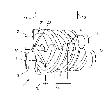
Fig. 1 shows the perspective illustration of the screws of a retruder.

~ 21 1 94 39
4
(t~ AT LEAST ONE MODE FOR CARRYING OUT THE INVENTION
The retruder 1 in Figure 1 is illustrated without a housing and only shows the
two
mutually-meshing reversible screws 2, 3. The term "reversible screw" indicates
the
particular property of these screws, since both reversible screws change their
direction
14 of conveying to the reverse direction 15 by the inversion of the pitch
angles, which
are a function of the pitch 5 and the circumference of one of the two
reversible screws
2, 3, in the region of the reversing points 20, 21 and/or 30, 31. The absolute
values of
the pitch in the region of the direction 14 of conveying and the pitch of the
reverse
direction 15 can be different depending on requirements. A further important
property
of the two reversible screws 2, 3 is the fact that they rotate in opposite
directions 12, 13
and in a meshing manner. In the region of the reversing points 20, 30 and 21,
31 of the
reversible screws 2, 3 the meshing is performed such that the reversing
windings of the
reversible screws 2, 3 roll on one another in the manner of double helical
gearwheels.
The depth of the screw channel (the difference between the external radius and
the core radius of the reversible screws 2, 3) and the flank angle 4 form the
cross-section
of the screw channel as a function of the pitch angle. The cross-section of
the screw
channel can decrease with the flank angle 4 in the direction 14 of conveying
and cause
an increasing compression of the medium.
From charging 10, the medium passes into the screw channel of the reversible
screws 2, 3 and is conveyed as a result of the rotation in opposite directions
forcibly in
the individual turns, which are closed by the windings of the screw channel,
the housing
inner wall and the meshing screw, as far as the reversing points 20, 30 and
21, 31 in
accordance with the direction 14 of conveying. The mass transport conveyed in
the
reverse direction 15 presses against this mass flow from the plane of rotation
of the
common reversing points 20, 30, and 21, 31. Depending on the counter-pressure
of the
reverse direction, the frictional force in the medium is increased and the
axial load on
the screw bearings is reduced. The progressively-decreasing flank angles of
the reverse
direction 15 allow the mass transport of the medium to advance to the removal
point 11.
Because of the counter-pressure in the reverse direction 15, the pressure on
the seals of

21 1 94 3g
s
s
the adjacent bearings is considerably reduced so that the risk of damage to
the bearings
is correspondingly lessened.
The mass flow of the retruder 1 permits charging 10 and removal 11
perpendicular to the reversible screws 2, 3. Depending on requirements, the
housing of
the retruder 1 can be provided with a casing which is common and/or divided as
desired
and which permits heating and/or cooling of the retruder. Finally, the
possibility of
forming the reversible screws as a monobloc should also be pointed out. Thanks
to this
robust construction of the retruder, common sense will set the limits on
output.

Representative Drawing
A single figure which represents the drawing illustrating the invention.
Administrative Status

2024-08-01:As part of the Next Generation Patents (NGP) transition, the Canadian Patents Database (CPD) now contains a more detailed Event History, which replicates the Event Log of our new back-office solution.

Please note that "Inactive:" events refers to events no longer in use in our new back-office solution.

For a clearer understanding of the status of the application/patent presented on this page, the site Disclaimer , as well as the definitions for Patent , Event History , Maintenance Fee  and Payment History  should be consulted.

Event History

Description Date
Inactive: First IPC assigned 2021-10-27
Inactive: IPC expired 2019-01-01
Inactive: IPC from MCD 2006-03-11
Time Limit for Reversal Expired 2005-07-25
Letter Sent 2004-07-23
Grant by Issuance 2000-06-06
Inactive: Cover page published 2000-06-05
Pre-grant 2000-03-08
Inactive: Final fee received 2000-03-08
Notice of Allowance is Issued 1999-09-09
Letter Sent 1999-09-09
Inactive: Approved for allowance (AFA) 1999-08-12
Inactive: Application prosecuted on TS as of Log entry date 1999-05-20
Letter Sent 1999-05-07
Reinstatement Requirements Deemed Compliant for All Abandonment Reasons 1999-02-26
Reinstatement Request Received 1999-02-26
Reinstatement Requirements Deemed Compliant for All Abandonment Reasons 1999-02-26
Inactive: Status info is complete as of Log entry date 1998-09-02
Inactive: Abandoned - No reply to s.30(2) Rules requisition 1998-08-03
Deemed Abandoned - Failure to Respond to Maintenance Fee Notice 1998-07-23
Inactive: S.30(2) Rules - Examiner requisition 1998-02-03
All Requirements for Examination Determined Compliant 1996-06-27
Request for Examination Requirements Determined Compliant 1996-06-27
Application Published (Open to Public Inspection) 1994-02-03

Abandonment History

Abandonment Date Reason Reinstatement Date
1999-02-26
1998-07-23

Maintenance Fee

The last payment was received on 1999-07-22

Note : If the full payment has not been received on or before the date indicated, a further fee may be required which may be one of the following

  • the reinstatement fee;
  • the late payment fee; or
  • additional fee to reverse deemed expiry.

Please refer to the CIPO Patent Fees web page to see all current fee amounts.

Fee History

Fee Type Anniversary Year Due Date Paid Date
MF (application, 4th anniv.) - small 04 1997-07-23 1997-07-22
MF (application, 5th anniv.) - small 05 1998-07-23 1999-02-26
Reinstatement 1999-02-26
MF (application, 6th anniv.) - small 06 1999-07-23 1999-07-22
Final fee - small 2000-03-08
MF (patent, 7th anniv.) - small 2000-07-24 2000-07-17
MF (patent, 8th anniv.) - small 2001-07-23 2001-07-16
MF (patent, 9th anniv.) - small 2002-07-23 2002-07-23
MF (patent, 10th anniv.) - small 2003-07-23 2003-07-16
Owners on Record

Note: Records showing the ownership history in alphabetical order.

Current Owners on Record
ANTOGI AG
Past Owners on Record
ANTON ZIMMERMANN
Past Owners that do not appear in the "Owners on Record" listing will appear in other documentation within the application.
Documents

To view selected files, please enter reCAPTCHA code :


To view images, click a link in the Document Description column. To download the documents, select one or more checkboxes in the first column and then click the "Download Selected in PDF format (Zip Archive)" or the "Download Selected as Single PDF" button.

List of published and non-published patent-specific documents on the CPD .

If you have any difficulty accessing content, you can call the Client Service Centre at 1-866-997-1936 or send them an e-mail at CIPO Client Service Centre.


Document
Description 
Date
(yyyy-mm-dd) 
Number of pages   Size of Image (KB) 
Cover Page 2000-05-15 1 31
Representative drawing 2000-05-15 1 10
Representative drawing 1999-05-12 1 13
Abstract 1999-08-11 1 13
Description 1999-08-11 5 217
Claims 1999-08-11 2 58
Cover Page 1995-05-20 1 33
Abstract 1995-05-20 1 31
Description 1995-05-20 4 184
Drawings 1995-05-20 1 44
Claims 1995-05-20 2 61
Description 1999-02-26 5 222
Abstract 1999-02-26 1 13
Claims 1999-02-26 2 60
Courtesy - Abandonment Letter (Maintenance Fee) 1998-08-20 1 189
Courtesy - Abandonment Letter (R30(2)) 1998-09-28 1 171
Notice of Reinstatement 1999-05-07 1 173
Commissioner's Notice - Application Found Allowable 1999-09-09 1 163
Maintenance Fee Notice 2004-09-20 1 173
Correspondence 2000-03-08 1 31
Correspondence 1999-02-26 14 470
PCT 1994-03-18 16 551
Correspondence 1994-04-19 10 332
Fees 1999-02-26 1 37
Fees 1997-07-22 1 39
Fees 1998-08-20 3 195
Fees 1999-07-22 1 31
Fees 1995-09-18 2 61
Fees 1996-06-27 1 45
Fees 1995-07-19 2 55
Prosecution correspondence 1999-07-29 5 122
Courtesy - Office Letter 1996-07-30 1 42
Prosecution correspondence 1994-03-18 8 301