Note: Descriptions are shown in the official language in which they were submitted.
CA 02119769 2004-05-12
METHOD AND SYSTEM FOR POINT BY POINT MEASUREMENT OF
SPATIAL COORDINATES
The present invention relates to an opto-electronic system for point by point
measurement of spatial coordinates. More specifically, the invention relates
to a
method and system for point by point measurement of spatial coordinates, where
a
touch probe comprising a minimum of three point sized light sources at known
coordinates relative to a local probe fixed coordinate system and with a touch
point at
a known location relative to said local coordinate system, is brought into
contact with
the point for which the coordinates are to be determined.
Said system is based on the use of opto-electronic angle sensors calibrated
for
measurement of angles in two dimensions (spatial direction) towards active
light
sources or diffuse light reflexes, e.g. as described by the inventors in
Norwegian
Patent No. 165046.
The present invention proposes a system solution using one angle sensor in
1 S combination with a measurement probe as described by the inventors in
Norwegian
Patent 169799, and in Swedish Patent No. 456 454.
A system according to the invention described in Norwegian Patent No. 165046
allows registration with high precision of the position, orientation and or
surface
geometry of objects, either static or dynamic. This is only to a limited
extent possible
by existing non-contact measurement techniques. The flexibility and
transportability
of the system makes it applicable for measurement tasks that can not be solved
by
conventional mechanical coordinate measurement machines. Such machines are
large
and complex, expensive and less flexible. The system is optimized for high
accuracy.
~VtD 9/07443 P(: C/ld~92100167
~ ~.19'~ 6 9 ~ ~~:v
As one angle sensor alone gives the information of the
direction towards a point only, conventionally two or more
angle sensors are used in combination. The spatial coordinates
of a point are calculated by a so called intersection tech- . ,
pique. Starting from known coordinates of 'the angle sensors,
as well as the measured spatial directions, the,co~ordina-tes are .
calculated for the point where the lines o~ sight~from the
individual angle sensors intersect. In the case of using two
angle sensors the intersection angle shall be as close to 90
degrees as possible to obtain optimum accuracy in all three
dimensions (~, y,,z). This introduces high requirements for
free sight, since..:all measurement points have to be seen from
at least two elifferent directions. This may be a problem in
indtastrial applications, since the object to be measured is
often partly or completely hidden by robots or other production
equipment.
The present further development suggests a simplified system
based on one angle sensor and a special made touch probe.
Spatial coordinates can be determined by the use of only one
angle sensor, if the touch probe is equipped with a minimum of
three measurement points at l~nown locations relative to the
touch point of the probem The use of a, touch probe eliminates
sighting problems, both by the fact that the measurement point
itself must not be seen b~ the angle sensor as long as all of
the measurement points of the probe are seen; ana that tho Line
~~ sight requirements are reduced to hat of one angle sen~c~r
only. This Leads to d: simplified satrap of the angle sensor,
better' access to difficult areas, better transportability, and
so increased me~sur~men~t ~peed.~
Normallg, a system based on dne angle sensor only, will not
give the same accuracy in spatial coordinates as systems b~.sed
on a plurality of angle sensors of corresponding type
Especially this is the case for the direction of depth relative
to the angle sensox. However, there are a number of geometry
measurement tasks where the fle~zibility and measurement speed
VVQ 93/07443 ffT/1~1092d00167
requirements are higher than the accuracy requirements.
Furthermore, there are a number of industrial measurement
problems where a. high accuracy is required in two dimensions,
but less in depth, e.g. the determination of the straightness
and roundness of an aircraft fuselage.
Norwegian Patent No. 165046 describes a fullyautomatic and
accurately calibrated angle sensor as shown in fig. 1. That
sensor is developed to measure the direction towards points
o like active light sources or points illuminated by active light
sources. This ensures secure measurement point identification,
and hence allows automatic operation, as well as ensures a very
high signal to noise ratio and hence contributes to high
accuracy.
The angle sensor mainly comprises a camera housing 1, a lens
unit 2 and a two dimensional array (matrix ) 3 of photosensi rive
elements 5. The lens unit is a camera lens with standard,
spherical optics, having a focal distance mainly given by the
o field of view requirements. Posaibly, the lens may have an
anti-reflection coating or optical filter, which has to be
matched to the spectral distribution of the light sources to
be used. The photosensitive elements mad e.g. be of CC~ (Charge
Coupled device) or CII3 (Charge Tn~ected device) type. Due to
~5 the accuracy requirements, nqr~~.lly matrices of maximum
resolution will be applied. If the system speed is of main
importance, matrices having fewer elements dill be applied.
~~.gh accuracy is ensured by the use of accurate pr~cedure~ to
calibrate the angle sensor: This is described in N~rwsgi~,n
o Patent No. 165046.
Figure 2 shows the principle for spatial direction measure-
ments. The fully a~xtomatic function of the angles sensor is
based on the use of active light sources, e.g. light emitting
~5 diodes 6. The image of the light emitting point b given by the
lens system 2 is an illuminated spot 7 on the array of
photosensitive elements 3. The image illuminates a number of
CA 02119769 2004-05-12
4
elements 5 with an intensity distribution given by the size of the emitting
point, and
the resolution of the lens system. The position of the illuminated spot is an
unambiguous measure of the spatial direction towards the imaged point. The
spatial
direction is given as two angles ~ and 13. 13 is the angle between the spatial
direction
and the horizontal plane of symmetry of the angle sensor, « is the angle
between the
optical axis 4 and the directions towards the projection of the light emitting
point into
the horizontal plane of symmetry. Both angles « and 13 have values 0 at the
optical
axis.
In the present invention, it is suggested to use one angle sensor in
combination with a
touch probe equipped with a minimum of three light sources in known
coordinates
relative to a local, probe fixed coordinate system. In addition, the touch
probe has a
touch point (reference point) which as an example can have a shape of a needle
tip.
By knowing the location of this point relative to the local coordinate system,
the
position of the touch probe can be related to this point.
Essentially, the touch probe will function as described in Swedish Patent No.
456 454,
and may have exchangeable tools as described in Norwegian Patent 169799.
Figure 3
illustrates a probe for determination of the coordinates of a point. The probe
comprises a body 8, three light sources 9 - 11, and a touch point 12 shaped as
a needle
tip.
According to the present invention, the method is characterized in that a
single opto-
electronic angle sensor designed to measure the spatial direction to point
sized light
sources, is located such that its field of view / working area basically
covers the object
to be measured, and such that the light sources of said touch probe will be
visible to
the angle sensor for all measurement points in question, that spatial
direction for each
of the light sources of said touch probe are registered simultaneously, and
that the
position and orientation of the touch probe relative to said single angle
sensor are
wo ~~io~~w3 ~cri~o9zioo~6~
_ 5 ~~~9769
computed from the registered spatial directions, and such that
the position of the touch probe is related to its touch point
with the measured object.
Further the system of the invention is characterized in a
single opto-electronic angle sensor designed,_to measure the
spatial direction -to point sized light sources,~and means for
computation of the position and orientation of the touch probe
relative to said single angle sensor based on the knowledge of
o the position of said light sources relative to the touch point
of the probe and the measured directions from the angle sensor
to the individual light sources, and such that the position of
the probe is related to said touch point.
5 According to further features of the system, according to the
invention, the system touch probe is connected to the data
processor of said system such that illumination time and
intensitg for each individual probe light source can be
controlled from the signal level that is at any time registered
20 ~y the ~.ngle sensor.
Also, said light sources exhibit a well defined and known
spectral distribution, and that the angle sensor has an
optical filter that matches 'this distribution.
Further features of the meth~d are suggested, wherein the
coordinates of a set of object poi~.ts are measured repeatedly,
usi~ag different locations ef the angle sensor relative to the
o'b~ect, and all measured coordinates are combined by a least
o squares analysis or bundle ~.d~ustment calculation to improve
-~he~ ~verall boordinate accuracy.
Further features of the invention are given in the following
description of examples being non-limitative to the invention,
~5 with references to the accompanying drawings.
VVt9 93/07443
P~'/N092/00167
_ 6 ,
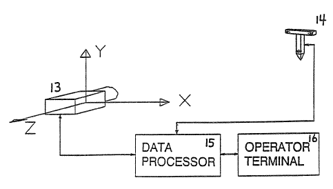
Figure 4 illustrates a system based on one angle sensor and
a touch probe.
Figure 5 illustrates a touch probe having 5 light sources.
Figure 4 illustrates a complete system for, point by point -
coordinate measurement. The system comprises an angle sensor
13, e.g. of the-same type as described in Norwegian latent No.
16504, a touch probe 14, a data processor 15, and an operator
~o terminal 1'b''~A coordinate measurement is made by bringing the
touch probe into contact with the object to be measured, such
that its touch point 12 touches the object in the point of
interest. The spatial direction towards each of the individual
light points of the probe are registered by the angle sensor
~5 13. All light emitting points are registered simultaneously,
such that for each registration there will be a number of
intensity magimas registered by the sensor's array of photosen-
sitive elements, corresponding to the number of light sources
in the touch probe.
The system's data processor 15 is responsible for the acquisi-
tion of measurement data from the angle sensor, and the
analysis of the data. The data analysis mainly includes:
2S - measurement~timing and exposure time control to optimize
the s~.,gnal to noise ratio,
identification of the individual light sources, i.e.
deiter~nina~tion of which spot in the i~ag~ that correspands
to which light source;
-- calculation of the spatial direction for each individual ,
light sou~°ce, based on the image information,
calculation of spatial coordinates for the touch probe.
WO 93!07443 PC I'/1~1~92/00167
The calculation of the spatial coordinates of the touch probe
is based on the known location of the individual light sources
relative to a probe fixed, local coordinate system. The
calculation principle may be based on conventional resection
s technique, or photogrammetric calculation methods. by the use
of photogrammetry technique, the projection of ,the light- points
into the array of photosensitive elements of the angle sensor
is evaluated. The pro~ect.ion can be described by a rotation and
translation matrix giving the position and orientation of the
touch probe relative to the angle sensor. The computation is
based on minimizing errors (least squares anal~rsis) by
utilizing redundant information. The necessary mathematical
basics can be found in H.M. Eamara (Ed.): Non-topographic
photogrammetr~r. Second Edition, 1987, page 37-55.
To do the computation it is essential to identifg the individu-
al light sources, i.e. which of the registered light spots in
the image corresponds to which of the light sources. This is
necessary for two reasons: to relate the measured directions
zo for each light point to the correct local coordinates for- that
point relative to the probe fixed coordinate system, and if it
is needed to adjust the light intensity or exposure time of one
of the l~.ght sources, to known which one. The touch probe will
be held manuall~r b~ an operator. 'fence it i~ important that all
Zs light s~urces are imaged simultaneousl~'to avoid errors due to
probe motions. This mans that the identification can not be
made b~ turning the light sources on in a sequence. Ths
identification procedure depehds on the shape of the t~u~h
probe : Furthermore , 1t should be possible to identify the l fight
points even if one or mare points are pissing in the rage,
e.g: if party of the probe is occluded by objects within the
fl.eld of view.
To achieve optimum accuracg, it is important to have as high
3s signal to noise ratio as possible. .~ method to achieve this is
to c~nnect the individual light sources of the touch probe to
the data processor such that the exposure time and / or current
P(:TllV~9~/00~ 67
.i
..
levels can be adjusted to optimum conditions based on the
measured intensity values for each light source. This method
makes the system very flexible with respect to the allowed
distance between the angle sensor and the touch probe.
The general ambient light or other light ,sources,-in the
measurement field may give the measurements a significant noise
contribution. To reduce this contribution, light sources of a
well defined spectral distribution can be used, and additional-
o ly the angle sensor can be equipped with an optical filter that
removes all light outside this spectral range.
Using the procedure as described, the calculated coordinates
will be given relative to a coordinate system defined by the
position and orientation of the angle sensor. The measurements
can be related to any coordinate system, as long as there is
a minimum of three points having well defined coordinates in
that coordinate system. Measuring the global coordinates of
these points, gives the necessary data to transform all
ao measured coordinate values to the local coordinate system.
Improved 3D coordinate measurement accuracy can be obtained by
combining measurements of the same points made from different
angle sensor locations around the object. The measurement data
25 can be analyzed ~~si.ng a least squares analysis or bundle
adjustment, 'based on the same mathematical concepts as used foa°
theodolite measurement data analysis. ~3y this method, the paor
accuracy in the depth direction relative to the angle sensor
is substituted by high accuracy measurements from other sensor
30 locat~.ons. '
If the system described in the present patent application is
used in combination ~rith a system based on two angle sensors
as described in ~dorwegian Patent No. 15046, it w~:11 be an
advantage first to position a number of au~il3.ary reference
points and to measure their accurate position relative to a
relevant coordinate system by the use of multiple angle sensor
WU 93/p7d43 PCI'/N0~2/OaA67
0
locations. Then, by using one or two angle sensors to measure
only a small part of the overall object, these auxiliary
reference points can be used to relate all measurements to the
correct coordinate system.
An operator terminal ib consisting of monitor,and keyboard is
connected to the data processor for the operator to communicate
with 'the system. This unit can as an example be used for
continuous and final presentation of measurement results.
The use of only one angle sensor to determine spatial coordi-
nates strongly restricts the shape of the touch probe. The
accuracy of the calculated coordinates depends on the shape and
size of the measurement probe relative to the distance to the
5 angle sensor. and the field of view of the sensor. The minimum
number of light sources is three, but this may give ambiguous
results and poor accuracy. In figure 5 a touch probe having 5
light sources is proposed, three ~pf these defines a plane, the
last two is separated from thi.: plane. Such a shape gives
2o significantly improved accuracy, as well as relatively simple
and secure identification of each light source.
Angle sensors as described in Norwegian Patent No. 165p46 are
assumed above. These can be replaced by other types of angle
2~ sensors, e.g. automatic theodolites. Normallg; th~adolites can
not register multiple light sources simultaneously, making the
data acquisition time consuming.
Tn the present context the term angle sensors shall include
so electro-optieal sensors'based on photogrammetric technique. In
ph~togramm~try a point is considered to be im~.ged through the
projection center of a lens system, and the direction is given
as the image coordinates of the rage of the point in the image
plane. The inner ~rientation of the camera, i.e. the parameters
35 describing the relation between spatial direction and the image
point have to be known.
'1~V0 9~/07g143 PC.T/N~92/00167
...~i ',.,~
The measurement system as described above solves a number of
measurement problems where at present no practically applicable
methods exist:
alignment and adjustment of industrial production cells,
where theodolites can not be used due to insufficient
s i gh t ; ~...~-
- crash tests in the automotive industry: how is the car
interior deformed? Theodolite systems and conventional
photogrammetry can only be used for determination of the
exterior deformation of the car body;
- surveying of the interior geometry of aircraft and
helicopter fuselages;
- determination of the dynamic behavior of an object, by
attaching the touch probe to the object to have a fi~ed
relation between, the inter°nal probe fixed coordinate
20 system of the probe and a local, object fixed coordinate
system.
Due to the automatic operation, the flexibility arid the simple
setup of the measurement system, it is quite compet~.tive
is relative to conventsozaa.l use of theodolites for ~. number of
applications:
surveying of the exterior geometry of aircrafts, helicop-
hers, cars etc, wl2ere the accuracy requirements are x~~t
~o as high in all ~pa,tial'dimonsions, e.g. straightness ~.nd
roundness of an aircraft fuselage;
- measurement of deformat~.on downward flexing) of e.g. an
aircraft wing;
~5
- high precision, large volume measurements using multiple
angle sensor locations; this can be applied to check the
a
WC9 9~/07~:i fC'1'/~1~92/00167
1 ~ 2 ~. .~ ~ ~ ~a~',
coordinates of a number of well defined control points,
or to establish a set of accurate reference points 'to be
used when measurements are made within smaller parts of
a large object.
. ..
--
~o
2U