Note: Descriptions are shown in the official language in which they were submitted.
W093/~37 ~ PCT/US92/08026
Title: PROCESS VARIA8LE MEASURING AND DISPLAY DEVICE
Field of the Inventlon
This invention relates to the field of pr~cess
variable measuring and d~splay devices. This invention
can be used to measure and display a process variable or
indicia, lncluding pressure, temperature, volume, and flow
rate. Speclf$cally, this invent~on relates to an elec-
tronic process variable measuring device electronically
coupled to a process variable display device which dis-
plays both a bar graph trend indication of the process
varlable and a digital display of the process variable.
. .
Descri~tion of the Prior Art
The measurement of process variables or parameters,
including but not limited to flow, volume, temperature,
~nd pressure, has long been important in industrial facil-
ities where fluid is stored, pumped, heated, and/or pres-
sur1zed. Such industries include petrochemical, power
generation, geophysical exploration and production, and
` food processing.
~- 25 In many industrial applications, it is desirable to
display the measured process variable at a location remote
from where the process variable is measured. Accordingly,
process instrumentation has evolved into process measuring
and display de~ices wherein the display device is remotely
- 30 located from the measuring device. In many applications,
adverse environmental conditions necessitate having a
process display device remotely located from the process
;' measuring device.
Early process instrumentation was mechanical in
nature. Examples of mechanical process instrumentation
included floats for measuring level, pitot tubes to
measure flow rate, and hydraulic devices for measuring
pressure. Such mechanical devices have limited accuracy
and are subject to phenomena such as hysteresis and
- SUBSTITUTE SHEET
W093/~37 PCT/US92/08026
temperature effects, whlch further limits their depend-
ability.
Another drawback of mechanical process variable
measuring devices is the limitation upon how remotely they
can be located from a transducer. For instance, in the
case of a bourbon tube for measuring pressure, the inter-
nal volume of fluid in the bourbon tube places a practical
limit upon the distance between the bourbon tube and its
associated transducer. Safety concerns may also limit the
degree to which mechanical process variable measuring
devices such as bourbon tubes may be separated from
process variable display devices. In many applications,
the process variable measuring device and the process
variable display device are connected by ~ressurized lines
or hoses. Such pressurized lines or hoses present safety
hazards in certain instances.
Environmental transients, such as changes in tempera-
ture, can also affect the accuracy of instrument readings
wherein a pressurized line or hose of hydraulic flu~d
connects the process variable instrument to the trans-
ducer.
Prior art process variable display devices have
appeared in the form of gauges wherein an analo~ reading
~s given by a needle, such as by a D'arsonval movement.
Such needle gauge displays tend to give an unsteady or
erratic reading, particularly during the measurement of
dynamic processes such as discharge pressure at the outlet
of a positive displacement pump. The reading on such
needle gauges is also affected by other dynamic phenomena
such as hysteresis and are generally slow in response due
to the inertia of the movement itself.
With the advent of liguid crystal display (LCD) tech-
nology, the needle gauge has been replaced in some appli-
cations with a multi-segment bar graph, each segment com-
3S prised of a liquid crystal element~ Such LCD analog dis-
plays, when coupled with mechanical process variable
measuring devices, are subject to many of the same inaccu
SUBSTITUTE SHEET
W093/ ~ 37 ~ l ~ Y ~l a PCT/US92/08026
racies and l~mltations as needle gauges. The resolution
of multi-segment bar graph display~ using LCD technology
ls a function of the number of LCD segments ln the display
for a given process variable range. The greater the num-
Sber of segments in the multi-segment display, the greater
the resolution of the display. Prior art mult$-~egment
bar graphs have utilized multiplexing in order to minimize
the number of electrical connections that must be input
into the multi-segment bar graph display. Although multi-
10plexing reduces the number of electrical connectlons, it
also reduces voltage contrast. For instance, in a tri-
plexed, multiplexed syætem, the voltage contrast is
reduced by a factor of three.
Digital displays have been used with process variable
15measuring devices to give a more precise indication of the
magnltude of the process variable being measured. When
coupled with mechanical process va-iable measuring devic-
es, such dlgital displays are inaccurate and unstable,
partlcularly durlng the measurement of dynamic processes.
20~Digital displays utilizing both LCD and LED technolo-
gy have become more common in recent years;. Electricity
- is necessary to power such displays. Many prior art
- instruments using LED'S or LCD's have relied upon AC power
supplles or house current. Such reliance is often unde-
25sirable in environments where house current may be inter-
rupted due to adverse environmental conditions such as
lightning strikes, earthguakes, or tornados. This is
particularly undesirable on offshore drilling and produc-
tion platforms where lightning strikes and other inclement
30weather conditions are common.
In many applications, it is highly deslrable that
process variable display devices be visible with the human
eye in less than optimal light conditions or from distanc-
es in excess of 35 feet. The visibility of multi-digit
35LCD displays is enhanced by increasing the size of the
dig~ts and by increasing the color contrast of the LCD
display. In order to increase both the size and color
~ :
SUBSTITUTE SHEET
WOg3/~37 X ~ 3 1 0 PCT/USg2/08026
contrast of LCD digits, the voltage contrast input into
the multi-digit LCD must be increased.
The magnitude of voltage contrast needed to power LCD
digits that would be visible by the human eye from a dis-
tance of over 35 feet is greater than the voltage contrastproduced in multiplexed systems. Thus, prlor art process
variable display devices have failed to combine both
multi-segment bar graphs and multi-digit ~CD's visible by
the human eye from a distance of over 35 feet, because the
voltage contrast requirements of each display are differ-
ent.
SU~A~Y OF THE INVENTION
The present invention relates to a process variable
measuring and display device with superior accuracy,
vers~tility, dependability, and display capabilities.
Superior accuracy is achieved by using an electronic
process variable measuring device rather than a mechanical
process variable measuring device. The electronic process
variable measuring device of the present ~nvention is not
sub~ect to the distance, accuracy and sensitivity limita-
tions of hydraulic devices. The electronic process vari-
- able measuring device of the pre~ent invention does not
require pressurized lines or hoses and thus avoids the
safety problems inherent with such pre~surized lines and
hoses.
The electronic process variable measuring device of
the present invention is more versatile than mechanical
measuring devices such as hydraulic lines. It can be used
to measure pressure in high pressure environments, such as
the choke manifold on a drilling rig. The electronic
process variable measuring device of the present invention
is not adversely affected by rapid temperature or pressure
changes as are hydraulic process variable measuring
devices.
The dependability of the present invention is superi-
or to that of the prior art due to the ability of the
SUBSTITUTE SHEET
WOg3/~37 ~ 9 1 ~ PCT/USg2/08026
present invention to run on battery power rather than AC
power or house eurrent. AC power supplies may be lnter-
rupted by adverse environmental eondit~ons. The present
lnventlon eomprises a portable power supply or portable
power paek whleh i8 sealed in a eaQlng eapable of proteet-
ing the power supply from ~dverse environmental eondition~
8uch as wind, rain, seawater, and abras~ve or eorrosive
ehemieals. The proeess variable measuring deviee of the
present invention operates on low eurrent, thereby permit-
ting the use of a portable power supply whieh, in a pre-
ferred embodiment, ean provide normal operating power for
at least 20 months.
The superior display eapabilities of the proeess
variable display deviee of the present invention are
aehleved by using both a muiti-segment bar graph display
~ to indieate the trend of the proeess variable being
- ~easured and a multi-digit LCD to provide an aeeurate
reàdln~g of the proeess variable being measured. The
stability and aeeuraey of both displays is superior to
that of prior art instruments whieh rely upon meehanieal,
rather than eleetrieal, proeess variable measuring devie-
es. The multi-segment bar graph display and the multl-
digit LCD of the present invention are eonfigured sueh
~ that t~ey ean be read with the human eye from a distanee
; 25 of over 35 feet. This superior display eapability is
aehieved by providing high color eontrast on both the bar
graph and multi-digit LCD displays and by providing large
digits on the multi-digit display. Both of these displays
are eontained within a housing along with the portable
`~ 30 power supply.
The present invention overcomes the problem of com-
bining a multiplexed display with a multi-digit LCD
requiring a large voltage eontrast by utilizing eustom
designed analog to digital convert~rs (ADC's) for eaeh
display.
Specifically, the proeess variable display device of
the present invention eomprises a first ADC with digit
~ SUBSTITUTE SHEET
wo g3/06437 ~ 0 ~ t.
drive capabilities configured to recelve a process vari-
able input signal from a proce~s var~able measuring
device, a second ADC with bar graph drlving capabllities
configured to receive a process varlable input slgnal from
S a process variable measurlng devlce, a multi-diglt LCD
electronically coupled to rece~ve an input signal from the
flrst ADC, and a multi-segment b~r graph electronlcally
coupled to recelve an input signal from the second ADC.
Thus, each dlsplay is separately driven by an ADC that is
configured to receive a process variable input signal from
a process variable measuring device.
A preferred embodiment of the present invention com-
prlses a portable power supply operatively coupled to
supply power to the first and second ADC's, the multi-
dlgit LCD, and the multl-segment bar graph. The portable
power supply also provides power to the sensor components,
lncluding a Wheatstone bridge. ~his power supply ls -apa-
ble supplying power to these components for at least 20
months. Thus, this preferred embodiment of the present
~nvention is superior to all prior art process variable
display devices that are dependent upon AC power or house
current for reasons previously discussed herein.
In another preferred embodiment, the process variable
display device of the present invention is housed in a
substantially cylindrical body with a removable display
face through which the multi-segment bar graph display and
the multi-digit LCD can be read. ~his cylindrical body is
dimensionally configured such that it can easily fit into
spaces in commercially available instrument panels where
prior art process variable display devices are presently
installed. Thus, the process variable display device of
the present invention is configured to easily replace
prior art process variable display devices without requir-
ing a replacement or modification of existing instrument
panels.
The present invention is also directed toward a
process variable measuring and display device comprising
~ SUBSTITUTE SHEET
W093/~37 ~ Q PCT/US92~08026
a process variable measuring device capable of producing
an electronic process variable input signal that is
proportlonal to the magnitude of the m~8ured process
variable, a dlrect drive ADC electronically coupled to
S receive an electronic process variable input signal from
the process variable measuring device, a multiplexed ADC
electronically coupled to receive an electronic process
variable input signal from the process variable measuring
device, a multi-digit LCD electronically coupled to
receive an input signal from the direct drive ADC, and a
multi-segment bar graph display electronically coupled to
receive an input signal from the multiplexed ADC.
, :
BRIEF DESCRIPTION OF THE DRAWINGS
FIGURE 1 is a block diagram of several embodiments of
the present invention. FIGURE 1 also includes FIGURES lA-
lJ which depicts the display drive waveforms, FIGURES lA-C
the direct drive and FIGURES lD-J the multiplexed wave-
forms.
FIGURE 2 is a schematic diagram of several embodi-
~ ments of the present invention depicting a physical
-~ embodiment of the multi-segment bar graph display and the
multi-digit LCD.
FIGURE 3A is an exploded front view of the process
variable display device.
FIGURE 3B is an exploded side view of the process
variable display device in its housing.
FIGURE 3C is a cutaway top view of the portable power
pack of the present invention.
FIGURE 4A is an isometric view of the process vari-
able measuring device in it casing.
FIGURE 4B is a side cutaway view of a preferred
embodiment of the process variable measuring device.
FIGURES 5 and 6 depict a block diagram of a fully
digital embodiment of the sensor and display units,
respectfully, of the present invention.
SUBSTITUTE SHEET
W093/~37 ~ n PCT/US92/08026
DESCRIPTION OF A PREFERRED EMBODIMENT
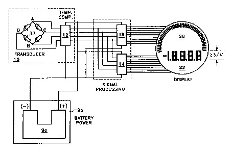
As shown in FIGURE 1, the process varlable measuring
device of the present inventlon comprises a first ADC with
dlglt drive capabilities 14 configured to receive a
S proce~s variable input signal from a process varlable
measurlng device 10, a second ADC wlth bar graph dr~ve
capabilitles 18 conflgured to receive a process variable
lnput signal from a process varlable measuring devlce 10,
a multi-digit LCD 22 electronically coupled to receive an
~0 input signal from the first ADC 14, and a multi-segment
bar graph 26 electronically coupled to receive an input
signal from the second ADC 18~
FIGURE 1 also includes FIGURES lA-lJ which depicts
the display drive waveforms, FIGURES lA-C the dlrect drive
and FIGURES lD-J the multiplexed waveforms. Figure lA
depicts the backplane waveform of the direct drive cir-
cu$t, while FIGUr~ES lB and lC depict the "ON" and ~OFF"
egment waveforms, respectively. The waveforms of FIGURES
lA-C cooperate to make ~CD segments visible or non-visible
ln a manner known in the art.
FIGURES lD-F depict the ~ON,~ nOFF,~ and ~UNIQUE~
backplane waveforms. The ON and OFF backplane waveforms
cooperate in a manner similar to that described with
regard to FIGURES lA-C to "activate" (make visible) indi-
vidual segments of the multi-segment bar graph display and
the UNIQUE backplane waveform ensures that all segments
from zero to the maximum segment activated remain visible.
The "ON" and "OFF" segment waveforms of FIGURES lG-H pro-
vide variations in contrast of the multi-segment bar
graph. This configuration minimizes pin overhead from the
bar graph driving ADC. Finally, FIGURES lI-J are included
for completeness but are not used in the display 26; they
may be uæed, for example, in activating indicators or
enunciators, such as low battery vo}tage.
A preferred embodiment of the present process vari-
able display device is depicted in FIGURE 2. As shown in
FIGURE 2, the multi-segment bar graph 26 has at least 42
Sll~ST~ r S~_
W093/~37 ~ PCT/US92/08026
segments. In the most preferred embod~ment, the multi-
segment bar graph 26 has 101 segments. As further shown
in FIGURE 2, the multi-digit LCD 22, comprises at least
three digits, each of which are at least 3/4 n hlgh. Thls
display permits v~ewing the process varlable from at least
about 35 feet. This display provides an additlonal advan-
tage in that it i8 viewable from about 30 elther side of
an axis perpendicular to the plane of the dlsplay. Assume
that the face of the display is the face of a clock. If
the display is tilted toward the viewer (i.e., viewing
from 12 o'clock), the display is viewable up to 15 of
tilt. If the display is tilted back away from the viewer,
to the left, or to the right, (i.e., viewing from 6, 3,
and 9 o'cIock respectively), the display is viewable up to
30 of tilt, with the optimum viewing angle at 6 o'clock.
As further shown in FIGURE 2, the second AD~ 18 is
multiplexed. The first ADC 14 is a dlrect drive ADC, as
shown in FIGURE 2. In a preferred embodiment, the first
and second ADC's are semiconductor chips, manufactured by
Harris Semiconductor, having model Nos. ICL7136 and
ICL7182, respectively. These semiconductor chips are
~; operable on a current of less than 1 milliampere, thus
~; facilitating the battery powered operation of the present
invention for periods of at least 20 months without
replacing the battery pack.
In a preferred embodiment, the present invention com-
prises a portable power supply 9A operatively coupled to
supply power to the first ADC 14, the second ADC 18, the
multi-digit LCD 22, and the multi-segment bar graph 26.
In a preferred embodiment, portable power supply 9A is
sealed in a casing 9B capable of protecting it from
adverse environmental conditions, as shown in FIGURE 3B.
As shown in FIGURE 3C, the portable power supply 9A com-
prises a plurality of individual batteries 15 a-b and 16
a-b enclosed within the casing 9B. The portable power
supply 9A housed in casing 9B constitutes a portable power
pack. In a preferred embodiment, portable power pack 9B
~ ~ SUBSTITUTE SHEET
,~ ~
W093/~37 PCT/US92/08026
~ .31 ~ 10
is operatively coupled to supply normal operating power to
dlrect drive ADC 14, multiplexed ADC 18, bar graph display
26, and multi-digit LCD 22 for a period of at least 20
months.
Portable power pack 9B is conflgured ln a preferred
embodiment to supply a voltage of at least seven volts, as
shown in FIGURE 3C. In a preferred embodiment, portable
power pack 9B comprises two pairs of llthlum batteries 15A
& 15B and 16A & 16B, connected ln parallel. The batteries
ln each pair of batterles are connected in series. As
shown in FIGURE 3C, battery 15A is connected in series
with battery 15B and battery 16A is connected in series
with battery 16B. In a preferred embodiment, portable
power supply 9A comprises an internal fuse that greatly
reduces the probability of explosion if the batteries are
short circuited. The battery may preferably be a Tadira D
lith~lum inorganic battery (Type TL-2300) or an Electrochem
CSC llthium oxyhalide primary cell (Series CSC93, 3B35).
; When configured as shown in FIGURE 3C, the batteries pro-
vide an average of about 7.23 volts and 28 ampere hours.
In a preferred embodiment, the bar graph display 26,
multi-digit LCD 22, and portable power pack 9B are con-
tained within a housing 20 as depicted in FIGURES 3A and
3B. Portable housing 20 comprises a substantially cylin-
drical body 19 and a removable face 25 through which bar
graph display 26 and multi-digit LCD 22 can be read.
Removable face 25 is secured to cylindrical body 19 by a
multiplicity of fasteners. In one preferred embodiment,
three fasteners 27 are equidistantly spaced in the outer
peripheral region 24 of removable face 25. In another
pre$erred embodiment, four fasteners 23 are equidistantly
spaced in the outer peripheral region 24 of removable face
25.
In a preferred embodiment, the present invention com-
prises a process variable measuring device 10 capable of
producing an electronic process variable input signal that
is proportional to the magnitude of the measured process
SUBSTITUTE SHEET
W093/~37 ~ 1 ~ 9 ~ l~ PCT/US92/08026
11
variable, as shown in FIGURES 2 and 4B. Process variable
measur~ng device 10 provides an input signal to direct
drive ADC 14 and multiplexed ADC 18.
In a preferred embodiment, process variable measuring
device 10 is a pressure sensor such as the piezoresistive
pressure sensor manufactured by KELLER PSI of Hampton,
Virginia, comprising a force collector 13 capable of being
deflected in an amount proportional to a pressure appl~ed
agalnst ~t and a strain gauge 11 mechanically coupled to
force collector 13. Strain gauge 11 is configured to pro-
~uce an electronic output signal proportional to the
deflection of force collector 13, as shown in FIGURES 2,
4A, and 4B. As shown in FIGURE 4A, the cylindrical compo-
nents depicted are a part of the Wheatstone bridge shown
in FIGURE 2.
In a preferred embodiment, strain gauge 11 comprises
a Wheatstone bridge configured t~ produce a differential
voltage electronic output signal as shown in FIGURE 2.
The electronic voltage output slgnal of Wheatstone bridge
11 is a differential voltage signal. The force collector
13 serves to protect the extremely delicate Wheatstone
which is embedded in the silicon substrate of the inte-
grated circuit. As the force collector detects a stress,
it transmits this information (through a silicone coupler
in the preferred embodiment) to the Wheatstone bridge.
This transmitted force flexes the Wheatstone bridge,
creating an imbalance in the bridge. This imbalance is
seen as a ratiometric shift in the two voltage outputs
from the bridge.
FIGURES S and 6 together depict an overall block
diagram of an embodiment of the present invention that
includes fully digital operation with microprocessor con-
trol. The circuit includes the process variable measuring
device 10 including the bridge circuit 11 and the compara-
tor 12. A power supply 9B provides power to the various
components. The circuit also includes an ADC (NA/D") 31
which is preferably located in vicinity of the sensor.
SUBSTITUTE SHE~T
WOg3/~37 PCT/US92/08026
(3
12
The ADC 31 provides a digital signal to a microprocessor
30 that processes the digital si~nal ln a manner previous-
ly described. In this way, the communication llnk between
the sensor and the display portions of the invention i8
digital and therefore much more immune to nolse and other
effects. The microprocessor 30 provides the processed
digital signal to a differential driver 32 that drives a
differential receiver 34 over a sensor link 36. The
microprocessor serves the addit~onal functions of compen-
sating for manufacturing variations from one sensor toanother and accommodating temperature variations. The
dr$ver 32 and receiver 34 provide sufficient power to
drive the components of FIGURE 6 and buffer the various
voltage levels. The differential receiver 34 provides the
digital signal to a microprocessor 38 which processes the
signal for reception by a digital to analog (~D/A") con-
verter 40. The microprocessor 38 also provides the timing
control for communication with the microprocessor 30 and
provides the capability with communicating directly with
external devices such as personal computers over an exter-
nal digital link 41. The D/A converter 40 provides an
analog si~nal to a set of LCD drivers 42 that drive the
LCD display 44. Preferably the LCD display 44 includes
the displays 22 and 26 on a single laminate, while each of
the displays 22 and 26 has its own display circuitry.
Many modifications and variations may be made in the
embodiments described herein and depicted in the accompa-
nying drawings without departing from the concept of the
present invention. Accordingly, it is clearly understood
that the embodiments described and illustrated herein are
illustrative only and are not lntended as a limitation
upon the scope of the present invention.
SU~STITUTE SHEET