Language selection

Search

Patent 2120107 Summary

Third-party information liability

Some of the information on this Web page has been provided by external sources. The Government of Canada is not responsible for the accuracy, reliability or currency of the information supplied by external sources. Users wishing to rely upon this information should consult directly with the source of the information. Content provided by external sources is not subject to official languages, privacy and accessibility requirements.

Claims and Abstract availability

Any discrepancies in the text and image of the Claims and Abstract are due to differing posting times. Text of the Claims and Abstract are posted:

  • At the time the application is open to public inspection;
  • At the time of issue of the patent (grant).
(12) Patent: (11) CA 2120107
(54) English Title: APPARATUS FOR SAMPLING A MATERIAL CONTAINING SOLIDS
(54) French Title: APPAREIL POUR L'ECHANTILLONNAGE DE MATIERES CONTENANT DES SOLIDES
Status: Term Expired - Post Grant Beyond Limit
Bibliographic Data
(51) International Patent Classification (IPC):
  • G01N 1/10 (2006.01)
  • G01N 1/20 (2006.01)
(72) Inventors :
  • MANN, KARI (Finland)
  • KARHU, LAURI (Finland)
(73) Owners :
  • OUTOKUMPU MINTEC OY
(71) Applicants :
  • OUTOKUMPU MINTEC OY (Finland)
(74) Agent: NORTON ROSE FULBRIGHT CANADA LLP/S.E.N.C.R.L., S.R.L.
(74) Associate agent:
(45) Issued: 2000-05-16
(22) Filed Date: 1994-03-28
(41) Open to Public Inspection: 1994-09-30
Examination requested: 1995-10-18
Availability of licence: N/A
Dedicated to the Public: N/A
(25) Language of filing: English

Patent Cooperation Treaty (PCT): No

(30) Application Priority Data:
Application No. Country/Territory Date
931404 (Finland) 1993-03-29

Abstracts

English Abstract

The invention relates to an apparatus for sampling a solids-bearing material that flows or is made to flow, the said apparatus comprising a sampling member (4) set in contact with the flowing material, and a sampling conduit (5) connected to the sampling member (4) in order to conduct the sample flow passing through the sampling member (4) to further treatment. According to the invention, in connection with the sampling member (4) there is movably installed a cleaning member (1), so that the cleaning member (1) can be at least partly inserted to the sampling member (4) when in working position.


French Abstract

L'invention concerne un dispositif pour l'échantillonnage d'un matériau contenant des solides qui s'écoule ou qui est amené à s'écouler, ledit dispositif comprenant un élément de prélèvement (4) mis en contact avec le matériau qui s'écoule, et un conduit de prélèvement (5) relié à l'élément de prélèvement (4) afin de conduire l'échantillon de débit traversant l'élément de prélèvement (4) à un traitement supplémentaire. Selon l'invention, en connexion avec l'élément de prélèvement (4) est installé de façon mobile un élément de nettoyage (1), de sorte que l'élément de nettoyage (1) puisse être au moins partiellement inséré dans l'élément de prélèvement (4) lorsqu'il est en position de travail.

Claims

Note: Claims are shown in the official language in which they were submitted.

6
The embodiments of the invention in which an exclusive
property or privilege is claimed are defined as
follows:
1. An apparatus for sampling a solids-bearing
material that flows or is made to flow, said apparatus
comprising a flow channel, a sampling member installed
in said flow channel with the flowing material, and a
sampling conduit connected to the sampling member in
order to conduct the sample current passing through the
sampling member to further treatment, characterized in
that in connection with the sampling member there is
movably installed a cleaning member, so that the
cleaning member can be at least partly inserted in the
sampling member, through an inlet of the sampling
member when in working position.
2. An apparatus according to claim 1, characterized
in that a shape of the cleaning member is, at least on
a surface directed towards the inlet of the sampling
member, essentially similar to that of the inlet of the
sampling member, but in cross-section smaller than the
inlet of the sampling member.
3. An apparatus according to claim 1, characterized
in that the cleaning member is knife-like in shape.
4. An apparatus according to claim 2, characterized
in that the cleaning member is knife-like in shape.
5. An apparatus according to claims l, 2, 3 and 4,
characterized in that a motion member for moving the
cleaning member is pneumatically operated.
6. An apparatus according to claims 1, 2, 3 and 4,
characterized in that a motion member for moving the
cleaning member is hydraulically operated.

7. An apparatus according to claims 1, 2, 3 and 4,
characterized in that a motion member for moving the
cleaning member is electrically operated.

Description

Note: Descriptions are shown in the official language in which they were submitted.


1
21 X0107
APPARATUS FOR SAMPLING A MATERIAL CONTAINING SOLIDS
BACKGROUND OF THE INVENTION
1. Field of the Invention
The present invention relates to an apparatus
for sampling a material that contains an essential
amount of solids and is advantageously in a flowing
motion or can be set to flowing motion.
2. Description of the Prior Art
From the Canadian Patent No. 1, 320, 850 there is
known an apparatus for sampling a material containing
solids, in which apparatus the sampling member is
connected to a guide member and suction member for
guiding the material current flowing from the sampling
member through the suction member to analysis. By using
the apparatus of the Canadian Patent No. 1,320,850, the
sample is extracted from a flowing material containing
solids. But if the sampling member of the Canadian
Patent No. 1,320,850 is blocked, the material flow must
be interrupted and the sampling member possibly
detached from the working position for cleaning. Thus
the blocking of the sampling member causes an
essentially long dead time in the operation, which
increases the operating expenses.
SUMMARY OF THE INVENTION
The object of the present invention is to
eliminate some of the drawbacks of the prior art and to
achieve an improved and operationally more secure
apparatus for sampling a material containing solids, in
which apparatus the disadvantage caused by a possible
blocking of the sampling member can advantageously be
alleviated by installing a cleaning member in
connection with the sampling member.

"",~., 2
21~0~0~
Therefore, in accordance with the present
invention, there is provided an apparatus for sampling
a solids-bearing material that flows or is made to
flow, said apparatus comprising a flow channel, a
sampling member installed in said flow channel with the
flowing material, and a sampling conduit connected to
the sampling member in order to conduct the sample
current passing through the sampling member to further
treatment, characterized in that in connection with the
sampling member there is movably installed a cleaning
member, so that the cleaning member can be at least
partly inserted in the sampling member, through an
inlet of the sampling member when in working position.
BRIEF DESCRIPTION OF THE DRAWINGS
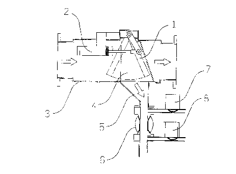
The invention is described below with reference
to the appended drawing, which is a cross-sectional
side-view illustration of a preferred embodiment of the
invention.
DESCRIPTION OF THE PREFERRED EMBODIMENTS
According to the drawing showing an apparatus in
accordance with the present invention, the direction of
the material current flowing in a flow channel 3 is
illustrated by means of arrows. In the flow channel 3,
there is installed a sampling member 4, on the first
surface whereof, in the flowing direction of the
material current, there is formed an aperture through
which the material current to be sampled enters the
sampling member 4, and then passes through a sampling
conduit 5 connected to the sampling member 4 to further
processing. According to the invention, a cleaning
member 1 is installed in connection with the sampling
member 4. The cleaning member 1 is movably arranged so
that the moving of the cleaning member 1 in between the
working position and the rest position is regulated by
a pneumatic cylinder 2. In the drawing the rest

.' . ~ 3 ~1 201 0 7
position of the cleaning member 1 is illustrated with
dotted lines. There are also illustrated valves 6, 7
and 8 connected to the sampling conduit 5, through
which valves liquids can be fed in countercurrent with
respect to the sample flow, in order to wash the
sampling conduit 5 and the sampling member 4.
In the apparatus of the invention, the sampling
member 4 is located in the flow channel 3, where the
material containing solids flows, or whereto the said
material can be made to flow. Advantageously the
sampling member 4 is so shaped, that it at least partly
resembles a truncated wedge and is essentially hollow
inside. Now the sampling member 4 is installed in the
flow channel 3 advantageously so that the converging
part of the advantageously wedge-like member is located
against the material current, so that the wedge-like
converging part forms an aperture, wherethrough the
material flow to be sampled enters the sampling member
4. The sampling member 4 can also be shaped so that in
the sampling member 4 there is provided an aperture in
the first wall essentially perpendicular to the flowing
direction of the solid material, through which aperture
the material flow to be sampled enters the sampling
member 4. Thus the sample flow that has entered the
sampling member 4 through the sample inlet is conducted
to further treatment through the sampling conduit 5
connected to the sampling member 4.
In connection with the sampling member 4 there
is movably installed the cleaning member 1 whereby the
sampling inlet of the sampling member 4 can be cleaned
of accretions possibly created by the solid material,
and thus the sample inlet of the sampling member 4 can
be prevented from getting blocked. The shape of the
cleaning member 1 provided in the apparatus of the
invention, at least on the surface directed towards the

,,..,.. , 4
~1 20107
sample inlet, is advantageously and essentially similar
to the shape of the sample inlet of the sampling member
4, but smaller in cross-section. Thus, when the sample
inlet is for instance a narrow aperture, the cleaning
member 1 can advantageously be for instance knife-like
in shape, so that the sharper edge of the cleaning
member 1 is directed towards the sample inlet of the
sampling member 4. In cross-section the cleaning member
1 is, at least partly, smaller than the sample inlet,
and therefore the cleaning member 1 can at least partly
be inserted to the sampling member 4 when in working
position.
The cleaning member 1 installed in connection
with the sampling member 4 is advantageously installed
so that the cleaning member 1 is movable in between the
working position and the rest position by means of a
pneumatically, hydraulically or electrically operated
actuator, e.g. the pneumatic cylinder 2. The actuator
2 regulating the operation of the cleaning member 1 is
arranged so that when the cleaning member 1 is in the
working position, it can freely move through the sample
inlet of the sampling member 4 to at least partly
inside the sampling member 4. On the other hand, when
the cleaning member 1 of the apparatus of the invention
is in the rest position, it is, by means of the
actuator 2, advantageously arranged so that it as
little as possible disturbs the material flowing in the
flow channel 3.
The operation of the cleaning member 1 of the
invention can advantageously be adjusted so that
operation commands are given to the motion member or
pneumatic cylinder 2 of the cleaning member 1
essentially regularly or only when desired. The
frequency of the operation commands essentially depends
on the solid content of the material under treatment,

,.... , 5
21 20107
i.e., on how much solids the material flowing in the
flow channel contains, and consequently on how severe
the danger of blocking in the inlet of the sampling
member 4 is.

Representative Drawing
A single figure which represents the drawing illustrating the invention.
Administrative Status

2024-08-01:As part of the Next Generation Patents (NGP) transition, the Canadian Patents Database (CPD) now contains a more detailed Event History, which replicates the Event Log of our new back-office solution.

Please note that "Inactive:" events refers to events no longer in use in our new back-office solution.

For a clearer understanding of the status of the application/patent presented on this page, the site Disclaimer , as well as the definitions for Patent , Event History , Maintenance Fee  and Payment History  should be consulted.

Event History

Description Date
Inactive: Expired (new Act pat) 2014-03-28
Inactive: IPC from MCD 2006-03-11
Inactive: Cover page published 2000-05-16
Grant by Issuance 2000-05-16
Inactive: Final fee received 2000-02-15
Pre-grant 2000-02-15
Notice of Allowance is Issued 1999-09-13
Letter Sent 1999-09-13
Inactive: Status info is complete as of Log entry date 1999-09-03
Inactive: Application prosecuted on TS as of Log entry date 1999-09-03
Inactive: Approved for allowance (AFA) 1999-08-20
Request for Examination Requirements Determined Compliant 1995-10-18
All Requirements for Examination Determined Compliant 1995-10-18
Application Published (Open to Public Inspection) 1994-09-30

Abandonment History

There is no abandonment history.

Maintenance Fee

The last payment was received on 2000-02-28

Note : If the full payment has not been received on or before the date indicated, a further fee may be required which may be one of the following

  • the reinstatement fee;
  • the late payment fee; or
  • additional fee to reverse deemed expiry.

Please refer to the CIPO Patent Fees web page to see all current fee amounts.

Owners on Record

Note: Records showing the ownership history in alphabetical order.

Current Owners on Record
OUTOKUMPU MINTEC OY
Past Owners on Record
KARI MANN
LAURI KARHU
Past Owners that do not appear in the "Owners on Record" listing will appear in other documentation within the application.
Documents

To view selected files, please enter reCAPTCHA code :


To view images, click a link in the Document Description column. To download the documents, select one or more checkboxes in the first column and then click the "Download Selected in PDF format (Zip Archive)" or the "Download Selected as Single PDF" button.

List of published and non-published patent-specific documents on the CPD .

If you have any difficulty accessing content, you can call the Client Service Centre at 1-866-997-1936 or send them an e-mail at CIPO Client Service Centre.


Document
Description 
Date
(yyyy-mm-dd) 
Number of pages   Size of Image (KB) 
Cover Page 2000-04-20 1 33
Representative drawing 1998-08-20 1 11
Representative drawing 2000-04-20 1 7
Cover Page 1995-06-09 1 40
Description 1995-06-09 4 208
Abstract 1995-06-09 1 28
Drawings 1995-06-09 1 38
Claims 1995-06-09 1 52
Description 1999-08-25 5 191
Claims 1999-08-25 2 47
Commissioner's Notice - Application Found Allowable 1999-09-13 1 163
Correspondence 2000-02-15 1 51
Correspondence 1995-11-01 1 45
Correspondence 1998-11-19 2 61
Fees 1997-02-19 1 56
Fees 1996-02-19 1 56