Language selection

Search

Patent 2120673 Summary

Third-party information liability

Some of the information on this Web page has been provided by external sources. The Government of Canada is not responsible for the accuracy, reliability or currency of the information supplied by external sources. Users wishing to rely upon this information should consult directly with the source of the information. Content provided by external sources is not subject to official languages, privacy and accessibility requirements.

Claims and Abstract availability

Any discrepancies in the text and image of the Claims and Abstract are due to differing posting times. Text of the Claims and Abstract are posted:

  • At the time the application is open to public inspection;
  • At the time of issue of the patent (grant).
(12) Patent: (11) CA 2120673
(54) English Title: PORTABLE SPA WITH INTEGRAL BOTTOM PAN, INTERCHANGEABLE SIDE SKIRT, AND INTERLOCKING COVER
(54) French Title: CUVE THERMALE PORTATIVE AVEC JUPE LATERALE INTERCHANGEABLE ET COUVERCLE INTERVERROUILLABLE
Status: Expired and beyond the Period of Reversal
Bibliographic Data
(51) International Patent Classification (IPC):
  • E04H 4/08 (2006.01)
  • A47K 3/022 (2006.01)
(72) Inventors :
  • WATKINS, JEFFREY KING (United States of America)
  • CUMISKEY, WALTER RICHARD (United States of America)
  • LOIZEAUX, PHILLIP DUDLEY (United States of America)
(73) Owners :
  • WATKINS MANUFACTURING CORPORATION
(71) Applicants :
  • WATKINS MANUFACTURING CORPORATION (United States of America)
(74) Agent: BORDEN LADNER GERVAIS LLP
(74) Associate agent:
(45) Issued: 1998-12-08
(22) Filed Date: 1994-04-06
(41) Open to Public Inspection: 1994-08-29
Examination requested: 1994-07-29
Availability of licence: N/A
Dedicated to the Public: N/A
(25) Language of filing: English

Patent Cooperation Treaty (PCT): No

(30) Application Priority Data:
Application No. Country/Territory Date
205,624 (United States of America) 1994-03-03

Abstracts

English Abstract


A portable spa including a cover having two
rigidly molded, interlocking halves, designed to conform
with the contour of the rim of the spa. The rim includes
a vertical extension which interfits with an extrusion used
to attach an interchangeable decorative vinyl-covered-kirt
about the side surface of the spa. The spa structure is
supported by an integral molded bottom pan, which provides
an upper edge or rim against which the lower edge of the
skirt is secured.


French Abstract

Cuve thermale portative comprenant un couvercle constitué de deux moitiés rigides d'enclenchement conçues pour s'adapter aux contours du bord de la cuve. Ce bord comporte un prolongement vertical qui s'ajuste avec un extrudat servant à fixer une jupe en vinyle décorative interchangeable autour de la surface latérale de la cuve thermale. La structure de la cuve est supportée par une base inférieure moulée intégralement qui forme un bord supérieur contre lequel le bord inférieur de la jupe peut être bien fixé.

Claims

Note: Claims are shown in the official language in which they were submitted.


-14-
We Claim:
1. A spa structure comprising:
a spa shell having an interior surface and an upper rim;
rigid foam insulation located adjacent said spa shell,
said insulation defining a side surface and a bottom surface
of the spa structure and providing structural rigidity to said
spa shell;
a molded bottom pan attached to said bottom surface;
a plastic skirt including a fastening mechanism
permitting removable and reattachable application of said
skirt about said side surface, said skirt, when applied about
said side surface, comprising an exterior surface of said spa
structure.
2. The spa structure of claim 1 wherein said upper rim has
an outer edge and said skirt has an upper edge, and further
includes extrusion means for interfittingly engaging said
outer edge and for retaining the upper edge of said skirt.
3. The spa structure of claim 1 further including a spa
cover comprising first and second rigid, pivotally
interlocking halves, said first half having a first linear
edge, said second half having a second linear edge.
4. The spa structure of claim 3 wherein said cover further
includes rim means for conformably surrounding the upper rim
of said shell.
5. The spa structure of claim 4 wherein said cover includes
an upper surface and a lower surface and a plurality of ribs,
each defined by a bell-shaped contour in said lower surface.
6. The spa structure of claim 4 wherein said first linear
edge includes a male hinge projection, a central finger, and
first and second side fingers, and wherein said second linear
edge includes female hinge means for interlocking with said
male hinge projection and said first and second side fingers.

-15-
7. The spa structure of claim 6 wherein said central finger
and first and second side fingers engage said female hinge
means in an interference fit.
8. The spa structure of claim 7 wherein said female hinge
means and male hinge projection cooperate to prevent
horizontal disengagement of said cover halves while permitting
such disengagement when one of the cover halves is raised to
an acute angle with respect to the horizontal.
9. The spa structure of claim 8 wherein said first and
second side fingers further exert a biasing force tending to
hold the first and second cover halves engaged.
10. The spa structure of claim 1 wherein said skirt
comprises:
a waistband panel having an upper loop means therein;
a lower vinyl panel attached to said waistband panel for
wrapping around the side surface of said spa structure, said
lower panel having first and second ends;
a backing means disposed between said lower panel and
said side surface; and
means for removably fastening together the ends of said
lower panel.
11. The spa structure of claim 1 wherein said bottom pan
comprises:
a substantially circular floor;
a vertical rim; and
means unitarily formed with said rim and floor and
attaching said rim to said floor.
12. The spa structure of claim 11 wherein said bottom pan has
a solid, water impervious base surface having a circular
periphery, said base surface providing the interface between
said spa structure and an installation site surface, and
wherein said molded bottom pan has an upper circular

-16-
peripheral edge lying in a plane parallel to, above, and
spaced apart from the plane of said base surface, said
circular peripheral edge meeting with said rigid foam
insulation.
13. An interchangeable spa skirt for attachment about a spa,
comprising:
a waistband panel having an upper loop means therein;
a lower vinyl panel means attached to said waistband
panel for wrapping around a side surface of said spa, said
lower panel means having first and second ends;
a backing means disposed between said lower panel and
said side surface; and
means for removably fastening together the ends of said
lower panel.
14. The skirt of claim 13, further including a lower loop
means in said panel means, and drawstring means in said lower
loop means for securing the lower edge of said panel about
said spa.
15. The skirt of claim 14 wherein said spa includes means for
interfittingly engaging said upper loop means.
16. The skirt of claim 15 wherein said means for
interfittingly engaging provides a generally cylindrical
opening, and further including spline means removably
insertable into the upper loop means and said cylindrical
opening for retaining said skirt in position adjacent said
side surface.
17. For attachment about a side surface of a portable spa
having an outer perimeter, an apparatus comprising:
a flexible plastic portable spa skirt means for
conforming to the shape of said side surface to provide a
decorative exterior surface and covering about said side
surface, said plastic skirt means having a top horizontal

-17-
edge, and a bottom horizontal edge, said top and bottom
horizontal edges being parallel to one another; and
attachment means for providing attachment of said top
horizontal edge continuously about substantially the entire
outer perimeter of said spa, said attachment means further
providing manual attachment, detachment, and reattachment of
said top horizontal edge about said outer perimeter; said
flexible plastic skirt means being manually attachable about,
removable from about, and reattachable about said outer
perimeter a plurality of times by user manipulation, including
user manipulation of said attachment means, after the spa has
been installed at a user site.
18. The apparatus of claim 17 further including means for
providing a snug fit between said bottom horizontal edge and
said spa and thereafter releasing said snug fit, said
attachment means and means for providing a snug fit
cooperating to provide attachment, detachment, and
reattachment of said flexible plastic skirt means about said
outer perimeter.
19. The apparatus of claim 18 wherein said means for
providing a snug fit comprises drawstring means for tightening
and untightening the fit between said bottom horizontal edge
and said spa.
20. The apparatus of claim 17 wherein said flexible plastic
skirt means has flap means located therein openable for
exposing operating equipment housed within said spa.
21. The apparatus of claim 20 further including panel means
disposed between said flexible plastic skirt means and the spa
for partially covering the spa and providing a cushioning
effect.

- 18 -
22. The apparatus of claim 21 further including drawstring
means for tightening and untightening the fit between said
bottom horizontal edge and said spa.
23. The apparatus of claim 17 wherein said attachment means
and flexible plastic skirt means further cooperate to provide
a water repellant engagement of said plastic skirt means to
thereby shield said spa from water splashed out of said spa.
24. The apparatus of claim 17 wherein substantially the
entire outer perimeter of said spa comprises at least 95% of
said outer perimeter.
25. The apparatus of claim 17 wherein said flexible plastic
skirt means comprises a vinyl skirt.
26. The apparatus of claim 17 wherein said portable spa is
circular and said outer perimeter comprises a circumference of
the spa and wherein the diameter defining the circumference of
said spa is six feet.
27. The apparatus of claim 26 wherein said spa has a height
of 27 inches.
28. The apparatus of claim 17 wherein said portable spa is
circular and said outer perimeter comprises a circumference of
the spa and wherein said spa has a height and diameter
selected to permit the spa to roll sideways through a standard
doorway.
29. The apparatus of claim 28 wherein said diameter is 6 feet
and said height is 27 inches.
30. The apparatus of claim 17 wherein said plastic skirt
means conforms to the shape of an elongated rectangle when
said skirt means is laid out on a flat surface.

-19-
31. The apparatus of claim 17 further including a means for
securing the bottom horizontal edge of said skirt about said
spa.
32. For attachment about a side surface of a circular
portable spa having a circumference, an apparatus comprising:
a plurality of flexible insulative plastic skirt means,
each of a different colour and each wrappable about said side
surface, each said skirt means providing a decorative surface
and covering about said side surface and having a top
horizontal edge and a bottom horizontal edge, said top and
bottom edges being parallel to one another; and
attachment means for providing attachment of said top
horizontal edge of each said skirt means continuously about
substantially the entire circumference of said spa, said
attachment means further providing manual attachment,
detachment, and reattachment of said top horizontal edge about
said circumference; each said flexible plastic skirt means
being manually attachable about, removable from about, and
reattachable about said circumference a plurality of times by
user manipulation, including user manipulation of said
attachment means, after said apparatus has been installed at
a user site.
33. The apparatus of claim 32 wherein each said skirt means
further has first and second ends, wherein said top and bottom
horizontal edges and at least one of said first and second
ends of each said skirt means conform along their periphery to
the shape of an elongated rectangle when each said skirt means
is laid out on a flat surface, and further including means for
manually fastening together said first and second ends of each
said skirt means after each said skirt means has been wrapped
about said side surface, whereby each said skirt means can be
manually attached one at a time about said spa and manually
released from said attachment.

-20-
34. For attachment about a side surface of a portable spa
means for containing a body of water and having an outer
perimeter, an apparatus comprising:
a flexible plastic portable spa skirt means for
conforming to the shape of said side surface for providing a
decorative exterior surface and covering about said side
surface, said plastic skirt means having a top horizontal
edge, and a bottom horizontal edge, said top and bottom
horizontal edges being parallel to one another; and
first means located along said top horizontal edge and
cooperating with the outer perimeter of said spa for providing
a snug fit of said top horizontal edge continuously about
substantially the entire outer perimeter of said spa, said
first means for providing a snug fit further facilitating
manual attachment, detachment, and reattachment of said top
horizontal edge about said outer perimeter; said flexible
plastic skirt means being manually attachable about, removable
from about, and reattachable about said outer perimeter a
plurality of times by user manipulation, including user
manipulation of said first means, after the spa has been
installed at a user site.
35. The apparatus of claim 34 further including second means
for providing a snug fit between said bottom horizontal edge
and said spa and thereafter releasing said snug fit, said
first means and second means for providing a snug fit
cooperating to facilitate attachment, detachment, and
reattachment of said flexible plastic skirt means about said
outer perimeter.
36. A portable spa apparatus installable at a user site and
comprising:
rigid foam insulation means for defining a
circumferential side surface and a bottom surface of a
circular spa structure having a circumference and for
providing rigidity to said structure, said side surface
exhibiting a vertical edge in side sectional profile;

-21-
a molded bottom pan positioned adjacent said bottom
surface of said rigid foam insulation means, said bottom pan
having a solid, horizontal planar, water impervious base
surface;
a flexible plastic skirt means for conforming to the
shape of said side surface for providing a decorative exterior
surface and covering about said side surface, said plastic
skirt means having a top horizontal edge and a bottom
horizontal edge, said top and bottom horizontal edges being
parallel to one another; and
attachment means for providing attachment of said top
horizontal edge continuously about substantially the entire
circumference of said spa structure, said attachment means
further providing manual attachment, detachment, and
reattachment of said top horizontal edge about said
circumference; said flexible plastic skirt means being
manually attachable about, removable from about, and
reattachable about said circumference a plurality of times by
user manipulation, including user manipulation of said
attachment means, after said apparatus has been installed at
a user site.
37. The spa apparatus of claim 36 further including means for
providing a snug fit between said bottom horizontal edge and
said spa structure and thereafter releasing said snug fit,
said attachment means and means for providing a snug fit
cooperating to provide attachment, detachment, and
reattachment of said flexible plastic skirt means about said
circumference.
38. The spa apparatus of claim 37 wherein said means for
providing a snug fit comprises drawstring means for tightening
and untightening the fit between said bottom horizontal edge
and said spa structure.
39. The spa apparatus of claim 36 wherein said flexible
plastic skirt means has flap means located therein openable

-22-
for exposing operating equipment housed within said spa
structure.
40. The spa apparatus of claim 39 further including panel
means disposed between said flexible plastic skirt means and
said rigid foam insulation means for covering said rigid foam
insulation means and providing a cushioning effect.
41. The spa apparatus of claim 40 wherein said means for
fastening comprises drawstring means for tightening and
untightening the fit between said bottom horizontal edge and
said spa structure.
42. The spa apparatus of claim 36 wherein said attachment
means and flexible plastic skirt means further cooperate to
provide a water repellant engagement of said plastic skirt
means to thereby shield said rigid foam insulation means from
water splashed out of said spa structure.
43. The spa apparatus of claim 36 wherein said base surface
of said bottom pan is circular and provides the interface
between said spa structure and an installation site surface.
44. The spa apparatus of claim 36 wherein substantially the
entire circumference of said spa structure comprises at least
95% of said circumference.
45. The spa apparatus of claim 36 wherein said flexible
plastic skirt means comprises a vinyl skirt.
46. The spa apparatus of claim 36 wherein the diameter
defining the circumference of said spa structure is six feet.
47. The spa apparatus of claim 46 wherein said spa structure
has a height of 27 inches.
48. The spa apparatus of claim 36 having a height and

-23-
diameter selected to permit said spa to roll sideways through
a standard doorway.
49. A portable spa apparatus comprising:
rigid foam insulation means for defining a side surface
and a bottom surface of a spa structure having an outer
perimeter and for providing rigidity to said structure;
a molded bottom pan positioned adjacent said bottom
surface of said rigid foam insulation means, said bottom pan
having a water impervious base surface;
a flexible plastic portable spa skirt means for
conforming to the shape of said side surface for providing a
decorative exterior surface and covering about said side
surface, said plastic skirt means having a top horizontal
edge, and a bottom horizontal edge, said top and bottom
horizontal edges being parallel to one another; and
first means located along said top horizontal edge and
cooperating with the outer perimeter of said spa structure for
providing a snug fit of said top horizontal edge continuously
about at least 95% of the outer perimeter of said spa
structure, said first means for providing a snug fit further
facilitating manual attachment, detachment, and reattachment
of said top horizontal edge about said outer perimeter; said
flexible plastic skirt means being manually attachable about,
removable from about, and reattachable about said outer
perimeter a plurality of times by user manipulation, including
user manipulation of said first means, after the spa structure
has been installed at a user site.
50. The apparatus of claim 49 further including second means
for providing a snug fit between said bottom horizontal edge
and said spa structure and thereafter releasing said snug fit,
said first means and second means for providing a snug fit
cooperating to facilitate attachment, detachment, and
reattachment of said flexible plastic skirt means about said
outer perimeter.

-24-
51. The apparatus of claim 50 wherein said skirt means
further has first and second ends, wherein said top and bottom
horizontal edges and at least one of said first and second
ends conform along their periphery to the shape of an
elongated rectangle when said skirt means is laid out on a
flat surface, and further including means for manually
fastening together said first and second ends of said skirt
means after said skirt means has been wrapped about said side
surface.
52. The apparatus of claim 50 wherein said skirtmeans further
has first and second ends, wherein said top and bottom
horizontal edges and at least one of said first and second
ends conform along their periphery to the shape of an
elongated rectangle when said skirt means is laid out on a
flat surface, and further including means for manually
fastening together said first and second ends of said skirt
means after said skirt means has been wrapped about said side
surface.
53. The apparatus of claim 52 wherein said portable spa
apparatus is circular and said outer perimeter comprises a
circumference of the spa structure, wherein the diameter
defining the circumference of the spa means is six feet, and
wherein said spa means further has a height of 27 inches.
54. A portable spa apparatus comprising:
rigid foam insulation means for defining a side surface
and a bottom surface of a spa structure and for providing
rigidity to said structure;
a molded bottom pan positioned adjacent said bottom
surface of said rigid foam insulation means, said bottom pan
having a water impervious base surface;
a flexible plastic portable spa skirt conforming to the
shape of said side surface, said skirt having a decorative
exterior surface for covering said side surface, a top
horizontal edge, and a bottom horizontal edge, said top and

-25-
bottom horizontal edges being parallel to one another, said skirt further having first and second
ends, said top and bottom horizontal edges and at least one of said first and second ends
conforming along their periphery to the shape of an elongated rectangle when said skirt is laid out
on a flat surface;
means for manually fastening together the first and second ends of said skirt; and
means for providing a snug fit between said bottom horizontal edge and said spa structure
and thereafter releasing said snug fit, said means for providing a snug fit and means for manually
fastening cooperating to facilitate manual attachment, detachment, and reattachment of said flexible
plastic skirt about said side surface.
55. For attachment about a portable spa having a side surface with a profile, the apparatus
comprising:
a flexible plastic portable spa skirt conforming to the profile of said side surface and
applied thereabout, said flexible plastic skirt including a top horizontal edge and a bottom
horizontal edge, said top and bottom horizontal edges being parallel to one another; and
means rendering said flexible plastic skirt manually attachable about, removable from
about, and reattachable about said side surface a plurality of times by user manipulation after said
spa has been installed at a user site, said means for rendering including a first fastening means for
providing a continuous releasable and reattachable water-repellent peripheral engagement between
said top horizontal edge and said side surface.
56. A spa structure comprising:
a spa shell providing an interior surface and having an upper rim;
rigid foam insulation means applied adjacent said spa shell for defining a side surface and
a bottom surface of the spa structure and for providing structural rigidity to said spa shell;
a molded bottom pan means attached to said bottom surface for sealing said bottom
surface; and
a plastic skirt means for removable and reattachable application about said side surface to
form an exterior surface of said spa structure.

Description

Note: Descriptions are shown in the official language in which they were submitted.


2120G 73
--1--
PORTABLE SPA WITH INTEGRAL BOTTOM PAN,
INTERCHANGEABLE SIDE SKIRT,
AND INTERLOCKING COVER
BACKGROUND OF THE INVENTION
1. Field of the Invention
The subject invention relates to spas,
whirlpools, and the like and, more particularly, to
improvements in portable spas.
2. Description of Related Art
Portable spas are generally known in the prior
art and have become increasingly popular as a source of
relaxation and physical therapy. Their structure generally
includes a spa shell or "tub" fabricated of various
materials such as fiberglass/acrylic or various thermo-
plastics, a layer of thermal insulation placed against the
shell, and a wooden support structure, often employing a 2
x 4 frame. In many cases, the exterior of the spa is a
continuation of the shell. In some cases, decorative
redwood patterns have been applied to serve as the exterior
sidewalls or "skirts" of free-standing units. Decorative
tile work has also been variously used in the interior and
exterior design of portable spas.
Another known portable spa design employs a "soft
core" - an inner annular core of "spongy" foam - together
with a vinyl outer surface sewn to an inner vinyl liner
much like a vinyl pool liner. The bottom of the spa is
formed of a flat sheet of thin plastic cut, e.g., by
scissors and stapled to the soft foam core. Because of its

2120673
~_ -2-
structure, the spa equipment, such as heaters and pumps,
must be located remote from the spa.
In order to retain heat and reduce evaporation,
portable spas have been fitted with insulating covers. The
most commonly used cover is made of cut styrofoam halves
surrounded by a sewn vinyl covering and permanently hinged
together. This structure provides a flat cover, which is
simply slid over the top of the spa when the spa is not in
use. Another known spa cover for use with the "soft core"
design is formed of one-piece polyethylene foam with a
hand-sewn cover and fits into the spa like a cork. Other
covers have employed foam cores with more resilient rigid
covering materials and have employed various spring-biased
hinged mechanisms for raising and lowering because of their
considerable weight.
To meet industry safety standards such as ASTM
F1346-91, spa covers must meet static load, deflection, and
surface drainage standards. Under ASTM F1346-91, a spa
cover must support a weight of 485 pounds. A deflection
test must be met to ensure that if a child under five falls
on the cover, he cannot slip through any openings. The
surface drainage standard ensures that the cover will not
retain enough water to risk drowning of a small child.
The prior art designs referenced above have a
number of drawbacks. Exposed or partially protected bottom
surfaces of many conventional spas are subject to attack by
rodents and weather. While generally attractive, the
decorative exterior of the spa is not always suited to the
particular aesthetics of the moment. The conventional spa
covers are labor intensive to manufacture, cumbersome to
use, and have a notoriously short life span in the face of
hot chlorinated water, sunlight, and the wear and tear of
use. Many of the designs, such as the soft core "cork,"
cannot meet industry safety standards.

2120~73
_ -3-
OBJECTS AND SUMMARY OF THE INVENTION
It is therefore an object of the invention to
improve various aspects of spa design;
It is another object of the invention to improve
portable spa design;
It is another object to increase the life of
covers used in conjunction with spas;
It is another object to improve the ease of use
of spa covers;
It is another object to provide a spa cover
design which is relatively lightweight and easy to use and
which can meet industry safety standards;
It is yet another object to improve the
resistance of portable spas to weather, rodents, and other
degrading factors; and
It is still another object to provide a
decorative, interchangeable skirt to improve the appearance
and utility of portable spas.
According to the invention, an improved portable
spa structure integrating several novel aspects into the
overall design is provided. The spa includes a lid or
cover with rigidly molded, interloc]~ing halves, designed to
rest on the upper rim of the spa. An interchangeable
decorative skirt wraps about the side of the spa, providing
a decorative feature readily changed by the user. The
skirt is retained by an extrusion member which interfaces
between the upper rim of the spa and the skirt. At its
lower edge, the skirt meets an integrally molded bottom
pan, which supports the entire structure and is impervious
to the elements.
BRIEF DESCRIPTION OF THE DRAWINGS
The objects and features of the present
invention, which are believed to be novel, are set forth
with particularity in the appended claims. The present
invention, both as to its organization and manner of
operation, together with further objects and advantages,

21201~73
-4
may best be understood by reference to the following
description, taken in connection with the accompanying
drawings.
Figure 1 is a side elevational view of a spa
according to the preferred embodiment;
Figure 2 is a perspective view of a typical spa
according to the preferred embodiment with the cover
removed;
Figure 3 is a partial side sectional view of a
spa according to the preferred embodiment;
Figure 4 is a top view of a spa base according to
the preferred embodiment;
Figure 5 is a side view of the base of Figure 4;
Figure 6 is a sectional view taken at 6-6 of
Figure 4;
Figure 7 is a sectional view taken at 7-7 of
Figure 4;
Figure 8 is a top view of the spa cover according
to the preferred embodiment;
Figure 9 is a sectional view taken at 9-9 of
Figure 8;
Figure 10 is a sectional view taken at 10-10 of
Figure 8;
Figure 11 is a sectional view taken at 11-11 of
Figure 8;
Figure 12 is a detail of a hinge according to the
preferred embodiment;
Figure 13 is a detail of a hinge according to the
preferred embodiment;
Figure 14 is a partial, cutaway perspective view
of a first half of the spa cover according to the preferred
embodiment;
Figure 15 is a partial, cutaway perspective view
of a second half of the spa cover according to the
preferred embodiment;
Figure 16 is an enlarged side sectional view of
an extrusion according to the preferred embodiment;

2120673
.~ -5-
Figure 17 is a side view of a spa skirt according
to the preferred embodiment;
Figure 18 illustrates a side sectional view of
the spa skirt of Figure 17; and
Figures 19-21 are side perspective views illus-
trating installation of the skirt according to the
preferred embodiment.
DETAILED DESCRIPTION
OF THE PREFERRED EMBODIMENTS
The following description is provided to enable
any person skilled in the art to make and use the invention
and sets forth the best modes contemplated by the inventor
of carrying out his invention. Various modifications,
however, will remain readily apparent to those skilled in
the art, since the generic principles of the present
invention have been defined herein specifically to provide
readily manufacturable and particularly useful portable spa
improvements.
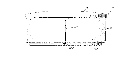
Figure 1 illustrates a spa 11 according to the
preferred embodiment including a cover 13, a decorative,
interchangeable side skirt 15, and a bottom pan 17. The
skirt 15 includes a zipper 132 and is removable and
replaceable by skirts of, for example, different colors.
Figure 2 shows a typical interior configuration
of the spa 11, including jet openings 25 and seating areas.
The particular interior detail is, of course, variable, as
will be appreciated by those skilled in the art.
As shown in Figure 3, the spa interior is
provided by a molded shell 19, which may be molded from
fiberglass, acrylic, polypropylene, or other materials.
The shell 19 includes a crowned upper rim 20 having a
depending vertical edge or lip 106. Adjacent the shell 19
is a layer of rigid foam insulation 21 which defines the
exterior contour of the spa 11, providing a bottom surface
18 and a side surface 22. The foam insulation 21 is
preferably a rigid, two-pound density, closed cell,

'. ~ 2120673
-6-
polyurethane foam. The bottom surface 18 is contoured to
conform to the interior surface shape of the bottom pan 17.
The bottom pan 17 itself is waterproof and is glued to the
rigid foam insulation 21 in order to provide a sealed,
water impervious surface. The interchangeable skirt 15 is
positioned adjacent the side surface 22 and includes
interior foam padding or batting 23 and a backing layer of
cloth material 24. The upper edge of the interchangeable
skirt 15 inserts within the lower edge of an extrusion 16,
which attaches to the depending vertical edge 106 of the
spa rim 20, as described below in more detail.
The bottom pan 17 is shown in more detail in
Figures 4-7. The bottom pan 17 is preferably molded
polyethylene and has a generally circular floor 30
surrounded by a contoured rim 31. A cutout 33 is formed in
a portion of the rim 31 to provide ventilation to housed
equipment such as a pump and heater. As shown in Figure 7,
a generally undulating surface 37 interconnects the rim 31
to the floor 30 of the bottom pan 17. The undulating
surface 37 descends to the floor 30 through first and
second 90-degree bends 36 and 38, first turning vertically
downward through bend 36, and then turning horizontally
through bend 38.
The top cover 13 according to the preferred
embodiment is shown in more detail in Figures 8-15. The
top cover 13 shown in Figure 8 is generally circular and
includes a female half 41 and a male half 43. These halves
41, 43 are adapted to abut one another along corresponding
edges 26, 28. Each half 41, 43 further includes three
identically-formed ribs 57, which separate or define four
pie-shaped sections 60. Each cover half 41, 43 is a
unitary part, preferably rotationally molded plastic,
although injection molding might be used.
As shown in Figure 9, each rib 57 is formed by
molding the bottom lower surface 66 of the particular cover
half 41, 43 to conform to a bell-shaped cross-section,
thereby forming a bell-shaped channel or impression 61. At

212067~
-7-
regular intervals, the bell-shaped channel 61 is further
provided with domes 63, which extend to meet a recess 68 in
the upper surface 64 of a respective cover half 41, 43.
Five such domes 63, equally spaced from one another, may be
provided in each rib 57. This overall structure provides
strenyth and rigidity to the respective cover halves 41,
43.
Additional intermediate channel areas 62 are also
preferably provided to add additional strength to the
structure. These channel areas may be substantially
identical in cross-section to that of the ribs 57 shown in
Figure 9. Two domes 63 are preferably provided in the
intermediate channels 62.
As further illustrated in Figure 9, openings 74
are provided in the lower surface 66 of each cover half 41,
43. These openings 74 are filled with foam beads such as
polystyrene beads, and then plugs 67 are inserted. The
beads provide insulation to the cover 13. Such beads could
also provide additional structural rigidity if the foam
beads were molded into a core at the end of the rotational
mold cycle.
In the foregoing manner, the cover 13 is provided
with an inner skin 66 and outer skin 64 spaced apart from
one another, for example, by a mean spacing of 70-80
millimeters, except at a number of selected areas where the
two surfaces are brought adjacent to one another by the
dome structures 63, thereby facilitating a rotational
molding process. A sealed interior providing desirable
insulation characteristics is additionally achieved.
As shown in Figure 10, the top surface of each
cover section 41, 43 angles gently downward to an outer rim
70, which includes an outer vertical wall 69 and an inner
vertical wall 71. The inner vertical wall 71 curves
through a 90-degree radius to a slightly recessed channel
73 molded to meet and rest on the rim 20 of the spa 11 in
order to provide an adequate and effective seal therewith.
If desired, this recessed area 73 may be provided with a

212067~
-8-
strip of insulating material to provide a seal between the
rim 20 and the cover 13. The rim 70 thus provides a
depending skirt which surrounds the outer circumference of
the spa 11 and retains the cover 13 in place on the spa 11.
The cover halves 41, 43 feature an integrally
molded interlocking hinge mechanism provided by an
elongated, tapered female hinge projection 51, an
elongated, tapered male hinge projection 50, a central
finger extension 47, and first and second side finger
extensions 45. Molded indentations 53, 55 (Fig. 8) of
rectangular cross-section may be provided to strengthen the
area behind the side finger extensions 45.
Figure 11 generally illustrates the cross-
sectional mating structure of the elongated, tapered
projections 51, 50 at the center of the two halves 41, 43,
while omitting the finger detail. Figures 12 and 13
illustrate in detail the hinge cross-section at the
location of the central finger extension 47 and the side
finger extensions 45, respectively. As shown, the male
projection 50 generally includes a bulbous portion 40
undercut to form a recessed receptacle portion 42, which
curves into a descending, angled floor portion 44. As
illustrated, this cross-section continuously and
symmetrically narrows from the center 46 of hinge
projection 50 toward each end 48 thereof, resulting in a
profile which generally recedes away from a relatively
prominent bulbous crown 46 at the center 46 toward the ends
48.
The female projection 51 is correspondingly
contoured to conform to the varying cross-section of the
receptacle 42 and the descending floor portion 44 presented
by the male projection 51. The resulting interlocking
structure cannot be pulled apart when both cover halves 41,
43 are horizontally disposed, but can be pulled apart when
one half is elevated to an acute angle with the horizontal,
the angle being determined by the geometry of the

'~ 2120673
~ 9
interlocking structure, particularly the upsweep of the
receptacle 42 and the clamping action between bulbous
portion 40 and the finger extensions 45, 47.
Thus, the two cover halves 41, 43, when lying on
5 a flat plane, e.g., when their inner surfaces 73 are
supported by the spa rim 20, are restrained from being
pulled apart in a horizontal direction by the interaction
of the hinge projections 50, 51 and the fingers 45, 47.
Engagement and release of these mated, hinged parts is
achieved by raising one of the cover halves 41, 43 to
approximately 40 degrees above horizontal. At that pOiIlt,
the hinged halves 41, 43 release and allow separation for
easier removal, handling, and storage.
The fingers 45, 47 exhibit resilience and are
15 further preferably disposed to provide an interference fit
or bias; that is, the fingers 45, 47 are depressed slightly
downward against their biased position as the cover halves
41, 43 interlock, and therefore tend to hold the cover
halves 41, 43 in interlocking relationship to create a
20 tight fit. This action is particularly desirable in the
face of molding tolerances. The fingers 45, 47 also
prevent the engaged cover halves 41, 43 from tending to bow
in or out, and thus serve to preserve the horizontal
interlocking relationship of the cover halves 41, 43.
The natural locking tendency of the two cover
shapes 41, 43 prevents horizontal separation and helps
maintain a weathertight seal for the spa. The natural
locking tendency of the two shapes 41, 43 further
discourages unwanted or unauthorized entry of persons into
the spa water, when used in conjunction with external
lockdown mechanisms (not shown), which secure the cover
halves 41, 43 to the spa proper. Thermal efficiency of the
complete package is promoted by reducing loss of heat from
the spa water that might occur with a nonjoined assembly of
35 cover halves. Such efficiency may be further promoted in
some configurations by placement of spongy insulation and

' 2120673
", ~
-10-
sealing material along the portions of the surfaces of the
abutting edges 26, 28 which lie adjacent the elongated
hinge projections 50, 51.
It may be noted that the structural advantages of
the cover ~3 shown in Figures 8-15 can be adapted to
various other cover shapes, for example square or
rectangular. In such case, support ribs may run linearly
rather than radially and the same or similar hinge
mechanism may be used.
Figure 16 illustrates the skirt retainer
extrusion 16 shown in Figure 3 in more detail. The
extrusion 16 is formed of PVC, for example, Gulf 7045 rigid
PVC or Hughes H-600 rigid PVC extruded to the length of,
for example, 20 feet, to substantially entirely surround
the circumference of the upper rim 20 of the spa 11. The
retainer extrusion 16 particularly provides a channel 92 of
circular cross-section having an opening 94 on a centerline
forming an acute angle, e.g., 56 degrees; with the
vertical. The opening 94 receives the upper edge 19 (Fig.
18) of the interchangeable skirt 15, while the channel 92
accommodates a retainer spline 113 (Fig. 19), as hereafter
described in more detail. A three-inch break 131 is
preferably provided in the channel 92 to facilitate skirt
attachment (see Fig. 19).
Above the channel 92 is a second channel lOl
having inner and outer side walls 103, 104 and an opening
100 in the top thereof. A projection 102 extends into the
channel 101 from the interior surface of the outer side
wall 103. The top opening 100 receives the vertical edge
106 of the top rim 20 of the spa 11. The edge 106 is
positioned within the channel 101 by the interior
projection 102. An exterior projection 90 also extends
from the outer surface of the inner side wall 104.
The opening 100 and projection 102 provide an
interference fit with edge 106. This interference fit
positions and retains the extrusion 16 in place around the
rim 20 of the spa 11. After the extrusion 16 is in place,

2120673
- 1 1 .
the high density foam 21 (Fig. 3) is applied against the
inner side wall 104 and about the projection 90, thereby
further fixing the extrusion 16 in place.
In fabricating the extrusion 16, it is desirable
to precoil it using a cold form bending procedure, as known
in the metal bending industry, to cause the extrusion 16 to
take on the shape of a six-foot-diameter circle. In such
a procedure, the extrusion 16 is fed between a grooved
aluminum wheel and two larger wheels with profiled
overmolded rubber. The larger wheels can be moved away
from the grooved wheel for loading the extrusion, and
toward it (locking at a preset distance) in order to induce
sufficient pressure to provide the degree of bending
necessary to achieve the desired diameter.
Figures 17-21 illustrate the interchangeable spa
skirt 15 in more detail. As shown in Figure 17, the spa
skirt 15 includes an upper waistband panel 110 comprising
a long, narrow rectangular vinyl section. The panel 110
may be, for example, 19 feet, 3 inches long by 3 inches
wide.
The waistband 110 is attached to a second
rectangular vinyl section 112 having a greater width, for
example, 21-1/2 inches, compared to the width of the waist-
band 110. A plurality of panels, e.g., 113, 114, 115, 116,
are formed by vertical and horizontal stitching. Such
stitching forms a lower loop 121, an upper loop 119, and
attaches the foam batting panel 23 and cloth backing layer
24. The batting panel 23 preferably gives a cushioning
effect and pleasing appearance, while taking up slack and
covering imperfections in the rigid foam 21.
As further shown in Figure 18, an upper hem 125
defines the upper loop 119, a lower hem 123 defines the
lower loop 121, and a seam 127 attaches the waistband 110
to the lower skirt panel 112. The waistband 110 terminates
in a three-inch flap 111, while the leftmost edge of the
lower skirt panel terminates in a flap 117. One of the
panels 116 further includes a flap 118 which may be opened

2120673
~""~, ,
-12-
and closed, for example, by means of VelcrolM fasteners in
order to expose the control panel (not shown) of the spa
11 .
As noted, a zipper 132 is used to attach the ends
of the lower vinyl section 112. A drawstring 127, for
example, a 1/8-inch nylon cord, is inserted in the lower
loop 121 to allow the lower edge of the skirt 15 to be
snugly fitted about the lower edge of the spa 11.
In attaching the skirt 15, the upper loop 119 is
inserted into the opening 94 of the skirt extrusion 16 in
order to retain the skirt 15 at the upper edge of the spa
11. As shown in Figure 19, a round spline 113 is provided
at a recess 131 in the skirt retainer 16, the spline 113
being driven in to fasten or retain the skirt 15 in
position.
Two people can easily install the skirt 15, one
person holding the skirt 15 in position, the second
wrapping the skirt 15 around the side 22 of the spa l1
while inserting the upper loop 119 into the opening 94 in
the skirt retainer 16. The zipper 132 is then closed. The
left portion of the skirt 15 may be installed and the left
spline 113 inserted, and then the right side of the skirt
installed and the right spline 113 (not shown) inserted.
The zipper flap lll is then tucked and the drawstring 127
tied or otherwise secured at the bottom.
The foregoing preferred embodiment exhibits a
number of advantages and improvements over the prior art.
The integral bottom pan 17 provides greater protection and
contributes to the ready portability of the overall spa
unit. To illustrate, a spa 27 inches high can be rolled on
its side through a 29-inch door. The decorative side skirt
15 can be changed, for example, from a more staid color to
a brighter one for festive occasions. The molded, two-
piece cover 13 is relatively lightweight, lasts twice as
long as conventional foam-based lids, can be fabricated to
meet ASTM safety standards, and provides other advantages
noted above.

- ' 2120673
......
-13-
Those skilled in the art will appreciate that
various adaptations and modifications of the just-described
preferred embodiment can be configured without departing
from the scope and spirit of the invention. Therefore, it
is to be understood that, within the scope of the appended
claims, the invention may be practiced other than as
specifically described herein.

Representative Drawing
A single figure which represents the drawing illustrating the invention.
Administrative Status

2024-08-01:As part of the Next Generation Patents (NGP) transition, the Canadian Patents Database (CPD) now contains a more detailed Event History, which replicates the Event Log of our new back-office solution.

Please note that "Inactive:" events refers to events no longer in use in our new back-office solution.

For a clearer understanding of the status of the application/patent presented on this page, the site Disclaimer , as well as the definitions for Patent , Event History , Maintenance Fee  and Payment History  should be consulted.

Event History

Description Date
Time Limit for Reversal Expired 2012-04-10
Letter Sent 2011-04-06
Inactive: IPC from MCD 2006-03-11
Grant by Issuance 1998-12-08
Pre-grant 1998-06-10
Inactive: Final fee received 1998-06-10
Letter Sent 1998-03-16
Notice of Allowance is Issued 1998-03-16
Amendment Received - Voluntary Amendment 1998-03-12
Inactive: Application prosecuted on TS as of Log entry date 1998-03-12
Inactive: Status info is complete as of Log entry date 1998-03-12
Inactive: IPC assigned 1998-02-04
Inactive: IPC removed 1998-02-04
Inactive: First IPC assigned 1998-02-04
Inactive: Approved for allowance (AFA) 1998-01-02
Application Published (Open to Public Inspection) 1994-08-29
All Requirements for Examination Determined Compliant 1994-07-29
Request for Examination Requirements Determined Compliant 1994-07-29

Abandonment History

There is no abandonment history.

Maintenance Fee

The last payment was received on 1998-03-13

Note : If the full payment has not been received on or before the date indicated, a further fee may be required which may be one of the following

  • the reinstatement fee;
  • the late payment fee; or
  • additional fee to reverse deemed expiry.

Please refer to the CIPO Patent Fees web page to see all current fee amounts.

Fee History

Fee Type Anniversary Year Due Date Paid Date
MF (application, 4th anniv.) - standard 04 1998-04-06 1998-03-13
Final fee - standard 1998-06-10
MF (patent, 5th anniv.) - standard 1999-04-06 1999-02-24
MF (patent, 6th anniv.) - standard 2000-04-06 2000-02-17
MF (patent, 7th anniv.) - standard 2001-04-06 2001-01-23
MF (patent, 8th anniv.) - standard 2002-04-08 2002-03-12
MF (patent, 9th anniv.) - standard 2003-04-07 2003-02-05
MF (patent, 10th anniv.) - standard 2004-04-06 2004-01-21
MF (patent, 11th anniv.) - standard 2005-04-06 2005-03-16
MF (patent, 12th anniv.) - standard 2006-04-06 2006-03-16
MF (patent, 13th anniv.) - standard 2007-04-10 2007-03-16
MF (patent, 14th anniv.) - standard 2008-04-07 2008-03-25
MF (patent, 15th anniv.) - standard 2009-04-06 2009-03-18
MF (patent, 16th anniv.) - standard 2010-04-06 2010-03-17
Owners on Record

Note: Records showing the ownership history in alphabetical order.

Current Owners on Record
WATKINS MANUFACTURING CORPORATION
Past Owners on Record
JEFFREY KING WATKINS
PHILLIP DUDLEY LOIZEAUX
WALTER RICHARD CUMISKEY
Past Owners that do not appear in the "Owners on Record" listing will appear in other documentation within the application.
Documents

To view selected files, please enter reCAPTCHA code :


To view images, click a link in the Document Description column. To download the documents, select one or more checkboxes in the first column and then click the "Download Selected in PDF format (Zip Archive)" or the "Download Selected as Single PDF" button.

List of published and non-published patent-specific documents on the CPD .

If you have any difficulty accessing content, you can call the Client Service Centre at 1-866-997-1936 or send them an e-mail at CIPO Client Service Centre.


Document
Description 
Date
(yyyy-mm-dd) 
Number of pages   Size of Image (KB) 
Description 1998-03-16 13 586
Cover Page 1998-03-16 1 19
Abstract 1998-03-16 1 18
Claims 1998-03-16 12 522
Drawings 1998-03-16 6 186
Cover Page 1998-12-04 1 43
Representative drawing 1998-12-04 1 7
Commissioner's Notice - Application Found Allowable 1998-03-16 1 165
Maintenance Fee Notice 2011-05-18 1 171
Correspondence 1998-03-16 1 100
Correspondence 1998-06-10 1 34
Fees 1997-03-05 1 38
Fees 1996-03-06 1 42
Courtesy - Office Letter 1994-11-29 1 47
Courtesy - Office Letter 1998-04-20 1 19
Examiner Requisition 1997-06-20 2 43
Examiner Requisition 1996-09-06 2 85
Prosecution correspondence 1994-07-29 1 22
Prosecution correspondence 1997-09-23 7 222
Prosecution correspondence 1997-03-06 4 154
Prosecution correspondence 1995-06-14 2 53
Prosecution correspondence 1995-02-23 3 50
Prosecution correspondence 1998-03-12 1 33