Language selection

Search

Patent 2120881 Summary

Third-party information liability

Some of the information on this Web page has been provided by external sources. The Government of Canada is not responsible for the accuracy, reliability or currency of the information supplied by external sources. Users wishing to rely upon this information should consult directly with the source of the information. Content provided by external sources is not subject to official languages, privacy and accessibility requirements.

Claims and Abstract availability

Any discrepancies in the text and image of the Claims and Abstract are due to differing posting times. Text of the Claims and Abstract are posted:

  • At the time the application is open to public inspection;
  • At the time of issue of the patent (grant).
(12) Patent: (11) CA 2120881
(54) English Title: STACKABLE LOAD BEARING TRAY
(54) French Title: PLATEAU PORTEUR GERBABLE
Status: Expired and beyond the Period of Reversal
Bibliographic Data
Abstracts

English Abstract

The disclosure herein describes a stackable tray which is formed of a body of rigid plastic material with a bottom wall integrally formed with opposite side walls and front and rear walls; each side wall is provided with an upper edge flange which is engageable in a recessed area defined in the lower edge of a superposed similarly constructed tray. The location of the recessed area with respect to the upper edge flange is such as to force outwardly the side walls during stacking engagement thus causing internal stresses in the bottom wall which counteract the sagging which occurs when loads are supported on the bottom wall.


French Abstract

La présente invention concerne un plateau empilable qui est formé d'un corps en matière plastique rigide avec une paroi de fond entièrement formée avec des parois latérales opposées et des parois avant et arrière; chaque paroi latérale est dotée d'une bride de bord supérieur pouvant être insérée dans une zone encastrée définie dans le bord inférieur d'un plateau superposé de même type. L'emplacement de la zone encastrée par rapport à la bride de bord supérieur est de nature à exercer une force vers l'extérieur sur les parois latérales lors de l'empilement, provoquant ainsi des contraintes internes sur la paroi de fond qui contrecarrent l'affaissement se produisant lorsque des charges sont supportées par la paroi de fond.

Claims

Note: Claims are shown in the official language in which they were submitted.

The embodiments of the invention in which an
exclusive property or privilege is claimed are defined as
follows:
1. A stackable tray comprising a body formed of
a rigid plastic material and consisting of a bottom wall
integrally formed with opposite side walls and opposite
front and rear walls, said front wall defining an access
area to allow removal of articles from said bottom wall
when said tray is in superimposed stacked relationship with
similarly constructed trays; each said side wall having an
upper edge defining an upstanding flange and a lower edge
including a recessed area to receive therein the upper edge
flange of a similarly constructed tray disposed
therebeneath; said recessed area, prior to stacking
engagement, extending in a vertical plane slightly offset
outwardly relative to a vertical plane including said upper
edge flange whereby, during stacking, said upper edge
flange forcingly engages in said recessed area causing an
outward movement of said side wall to thereby counteract
sagging of said bottom wall due to the weight of articles
placed thereon.
2. A stackable tray as defined in claim 1,
wherein said recessed area of said lower edge includes a
series of ribs displaying a lower sloping edge which is
contacted by said upper edge flange of a lower disposed
tray prior to be forcingly engaged in said recessed area.
3. A stackable tray as defined in claim 2,
wherein said recessed area displays, at opposite ends
thereof adjacent said front and rear walls, a transverse
rib; said upper edge flange displaying, at opposite ends
thereof adjacent said front and rear walls, a recess into

which the transverse ribs of a superimposed similarly
constructed tray are received during stacking.
4. A stackable tray as defined in claim 1,
wherein the height of each said side wall is greater than
the height of said front and rear walls and wherein the
distance between said side walls is greater than the
distance between said front and rear walls whereby the
trays are nestable with each successive tray being disposed
at 90° relative to one another.
5. A stackable tray as defined in claim 4,
wherein said front and rear walls display an upwardly
extending flange, each flange including, at opposite ends
thereof adjacent said side walls, a recess; and wherein
said bottom wall includes, adjacent said recessed area at
said lower edge of said side walls, a further recessed area
receiving therein said flanges of said front and rear walls
during nesting.
6. A stackable tray as defined in claim 5,
wherein each said further recessed area includes, at
opposite ends thereof adjacent said front and rear walls,
a block having a sloping face to assist in the nesting of
trays.
7. A stackable tray as defined in any one of
claims 1 to 6, wherein each said side wall includes a
series of openings; one of said openings being centrally
located and serving as a handle for carrying said tray.
8. A stackable tray as defined in any one of
claims 1 to 6, wherein said rigid plastic material is a
high density polyethylene.

Description

Note: Descriptions are shown in the official language in which they were submitted.


2~2Q88I
TITLE OF THE INVENTION
A stackable load bearing tray.
FIELD OF THE INVENTION
The present invention relates to a tray which
is adapted to be stacked with similarly constructed load
bearing trays.
BACKGROUND OF THE INVENTION
At present, bread loaves are transported and
delivered in stores in stackable trays which are formed
of a body of rigid plastic material and which consist of
a bottom wall integrally formed with opposite side walls,
a rear wall and a front low display wall. The structural
configuration of the trays is such that, for a stacked
arrangement, they are simply placed one on top of the
other, the lower edge of a tray resting on the upper edge
of the lower tray.
However, it has been found that, when the trays
are loaded with articles and a number of them are
stacked, there is a downward sagging force exerted on the
bottom wall on the front side thus causing an inward
movement of the side walls, which movement is further
increased as the number of loaded superposed trays
becomes important. One solution being used is to
increase the height of the front ribs while another

2~~088I
- 2 -
solution is to add a metallic reinforcement in the front
wall of the tray.
OBJECT AND STATEMENT OF THE INVENTION
An object of the present invention is to
overcome the above described problems with existing
trays, especially bread trays. This is achieved by
providing a tray which further enhances engagement when
trays are in a stacking arrangement. The construction of
the tray is such that, during stacking, an outward force
is exerted on the side walls resulting in an upward
bending moment in the bottom wall to thereby counteract
the forces exerted by the weight of the loads resting on
the bottom wall.
The present invention therefore relates to a
stackable tray which comprises a body formed of a rigid
plastic material and consisting of a bottom wall
integrally formed with opposite side walls and opposite
front and rear walls; the front wall defines an access
area to allow removal of articles, such as bread loaves,
from the bottom wall when the tray is in superposed
stacked relationship with similarly constructed trays.
Each side wall defines an upper edge with a flange and a
lower edge with a recessed area in which is received the
upper edge flange of a similarly constructed tray
disposed therebeneath. The recessed area, prior to
stacking engagement, extends in a vertical plane slightly
offset outwardly relative to a vertical plane including

2~.2~J88~
- 3 -
the upper edge flange whereby, during stacking, the upper
edge flange forcingly engages in the recessed area
causing an outward movement of the side wall which
counteracts sagging of the bottom wall due to the weight
of articles thereon.
In one form of the invention, the lower edge
includes a series of sloping ribs to assist in the
stacking engagement and in the outward movement of the
sidewall of a lower tray.
Other objects and further scope of
applicability of the present invention will become
apparent from the detailed description given hereinafter.
It should be understood, however, that this detailed
description, while indicating preferred embodiments of
the invention, is given by way of illustration only,
since various changes and modifications within the spirit
and scope of the invention will become apparent to those
skilled in the art.
BRIEF DESCRIPTION OF THE DRAWINGS
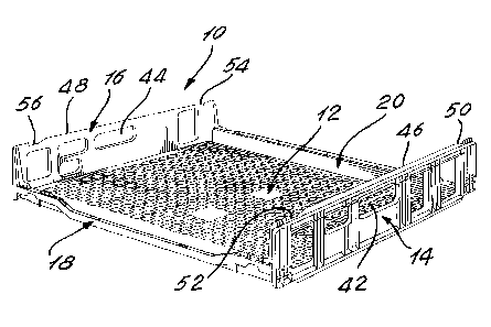
Figure 1 is a front perspective view a tray
made in accordance with the present invention;
Figure 2 is a front elevation thereof;
Figure 3 is a rear elevation thereof;
Figure 4 is a top plan view thereof;
Figure 5 is an enlarged fragmental bottom view
of one corner of the tray;

- 4 -
Figure 6 is an enlarged cross-sectional
fragmental view showing two superposed trays prior to
stacking;
Figure 7 is an enlarged cross-sectional view
similar to that of figure 6 showing the trays in contact
prior to engagement with one another;
Figure 8 is an enlarged cross-sectional view
similar to that of figure 6 showing the trays during
engagement;
Figure 9 is an enlarged cross-sectional view
taken along lines 9-9 of figure 5 and showing parts of
two trays in full engagement;
Figure 10 is a fragmental side elevation
showing two trays in a stacked condition; and
Figure 11 is a fragmental front elevation
showing two trays in a nested arrangement.
BRIEF DESCRIPTION OF THE DRAWINGS
Referring to figure 1, there is shown a
stackable tray, generally denoted 10, constructed in
accordance with the present invention and having a body
formed of a rigid plastic material, such as a high
density polyethylene, and consisting of a bottom wall 12
integral with opposite side walls 14 and 16, front wall
18 and rear wall 20.
Referring to figure 2, the front wall 18
displays an inverted U-shaped upper edge 22 including a
pair of horizontal side sections 22a and 22b, adjacent to

CA 02120881 2004-03-05
side walls 14 and 16 respectively, and a pair of inclined
sections 22c and 22d sloping down to a lower central
section 22e. Sections 22c, 22d and 22e define an access
area on the front wall allowing one to place or retrieve
5 articles on and from the bottom wall 12. Sections 22a and
22b display upwardly extending flanges 24 and 26,
respectively, each including a recess at 28 and 30.
Referring to figure 3, the rear wall 20 displays
an upper inverted U-shaped edge 30 extending horizontally
between the opposite side walls 14 and 16. The lower part
of the edge comprises two recesses 32 and 34 while the
upper part displays a vertically extending flange 36 which
also displays a pair of recesses 38 and 40.
Referring to figure 4, the bottom wall 12
displays a flat upper face that includes a series of
rectangular and triangular openings providing lightness to
the tray.
Referring also to figure 1, each side wall 14, 16
displays a series of openings, also to provide lightness to
the tray; two of these openings, 42 and 44, serve as
handles for carrying the tray. The side walls 14 and 16
respectively include an upper edge 46, 48, each displaying
two recesses 50, 52, and 54, 56.
Figure 5 shows a bottom view of one corner of the
tray; however, all four corners of the tray are of an
identical construction. The lower edge of each side wall
comprises an outer longitudinal flange 58 parallel to an
inner longitudinal flange 60. A longitudinal arrangement
of rectangular openings 62 formed by side walls 64 and 66
is disposed inwardly of flange 60. The lower edge of
flanges 58, 60, 64 and 66 is lower than that of the
remaining face of the bottom wall. Integral with flange 60
is a series of longitudinally spaced ribs 68 thus leaving
a gap or recessed area 70 between the vertical edge of the

CA 02120881 2004-03-05
6
ribs and the outer flange 58. Two of these ribs 68 (see
ribs 68a and 68b) located at opposite ends of the tray and
adjacent the front and rear walls, extend the full width of
the area 70 separating flanges 58 and 60. These ribs 68a
and 68b are in vertical alignment with the upper recesses
50 and 52 of the upper edge. Also, at each opposite end of
flange 60, adjacent the front and rear walls, are blocks
60a and 60b which have a sloping lower face, the function
of which will be described further hereinbelow. Similarly,
ribs 68 have a sloping lower edge, the function of which
will be described further hereinbelow.
Referring to figures 6, 7, 8 and 9, the nesting
steps of two superposed trays are illustrated. As can be
seen in figure 7, first contact between the two trays
occurs when the upper edge 46 of the lower tray contacts
the sloping edge of ribs 68 in the direction indicate by
arrow 72. In figure 8, as the upper tray is further
lowered, as indicated by arrow 72, the side wall 14 of the
lower ray is caused to move outwardly, as indicated by
arrow 74, as a result of the upper flange 46 being forced
into the recessed area 70. This outward movement-

~~~88~
of side walls 14 and 16 causes upward bending forces in
the bottom wall 12 of the tray. Finally, in the position
shown in figure 9, the two trays are shown fixed by
secured with the upper flange 46 being entirely received
within the area 70. The resiliency of the plastic
material of the tray tends to return the side walls to
their vertical position thus increasing frictional
contact between the parts and securing the nesting
engagement of the trays.
Referring to figure 10, the stacked trays are
prevented to move relative to one another in a direction
parallel to the side walls as a result of the ribs 68a
and 68b engaging their corresponding recesses 50 and 52
in the upper flange 46. Similar engagement is achieved
in the opposite side wall 16 of the tray.
The tray is preferably rectangular with the
front end rear walls being wider than the side walls so
that, when the trays are not used for displaying
articles, such as bread loaves, they may be nested in one
another such as illustrated in figure 11 with the front
and rear walls of a tray being received adjacent and
parallel to the side walls of a lower tray. The nesting
is facilitated by the upper flanges 24, 26 of the front
wall and 36 of the rear wall sliding along the sloping
lower faces of blocks 60a and 60b to thereafter slide
into the area between the blocks and the vertical flange
64.

2~2~881
_8_
Although the invention has been described above
in relation to a specific form, it will be evident to the
man skilled in the art that it may be modified and
refined in various ways. For example, an access area may
also be provided on the rear wall thus allowing removal
or placing of articles from or on both sides of the tray
when in stacked arrangement with other trays. It is
therefore wished to have it understood that the invention
should not be limited in interpretation, except by the
terms of the following claims.

Representative Drawing
A single figure which represents the drawing illustrating the invention.
Administrative Status

2024-08-01:As part of the Next Generation Patents (NGP) transition, the Canadian Patents Database (CPD) now contains a more detailed Event History, which replicates the Event Log of our new back-office solution.

Please note that "Inactive:" events refers to events no longer in use in our new back-office solution.

For a clearer understanding of the status of the application/patent presented on this page, the site Disclaimer , as well as the definitions for Patent , Event History , Maintenance Fee  and Payment History  should be consulted.

Event History

Description Date
Time Limit for Reversal Expired 2014-04-08
Letter Sent 2013-04-08
Letter Sent 2012-04-12
Inactive: Correspondence - Transfer 2012-04-04
Grant by Issuance 2005-08-30
Inactive: Cover page published 2005-08-29
Pre-grant 2005-06-16
Inactive: Final fee received 2005-06-16
Notice of Allowance is Issued 2004-12-22
Letter Sent 2004-12-22
Notice of Allowance is Issued 2004-12-22
Inactive: Approved for allowance (AFA) 2004-12-07
Amendment Received - Voluntary Amendment 2004-03-05
Inactive: S.30(2) Rules - Examiner requisition 2003-10-07
Amendment Received - Voluntary Amendment 2001-09-19
Inactive: Application prosecuted on TS as of Log entry date 2001-07-18
Inactive: Adhoc Request Documented 2001-07-18
Inactive: Delete abandonment 2001-07-18
Letter Sent 2001-07-18
Inactive: Status info is complete as of Log entry date 2001-07-18
Inactive: Abandon-RFE+Late fee unpaid-Correspondence sent 2001-04-09
All Requirements for Examination Determined Compliant 2001-04-03
Request for Examination Requirements Determined Compliant 2001-04-03
Application Published (Open to Public Inspection) 1995-10-09

Abandonment History

There is no abandonment history.

Maintenance Fee

The last payment was received on 2005-04-05

Note : If the full payment has not been received on or before the date indicated, a further fee may be required which may be one of the following

  • the reinstatement fee;
  • the late payment fee; or
  • additional fee to reverse deemed expiry.

Please refer to the CIPO Patent Fees web page to see all current fee amounts.

Owners on Record

Note: Records showing the ownership history in alphabetical order.

Current Owners on Record
IPL INC.
Past Owners on Record
MAURICE BEAUCHAMP
MICHEL LANOUE
Past Owners that do not appear in the "Owners on Record" listing will appear in other documentation within the application.
Documents

To view selected files, please enter reCAPTCHA code :


To view images, click a link in the Document Description column. To download the documents, select one or more checkboxes in the first column and then click the "Download Selected in PDF format (Zip Archive)" or the "Download Selected as Single PDF" button.

List of published and non-published patent-specific documents on the CPD .

If you have any difficulty accessing content, you can call the Client Service Centre at 1-866-997-1936 or send them an e-mail at CIPO Client Service Centre.


Document
Description 
Date
(yyyy-mm-dd) 
Number of pages   Size of Image (KB) 
Representative drawing 1998-07-29 1 29
Drawings 1995-10-09 7 249
Cover Page 1995-11-23 1 14
Description 1995-10-09 8 248
Abstract 1995-10-09 1 18
Claims 1995-10-09 3 80
Description 2004-03-05 8 255
Claims 2004-03-05 2 77
Representative drawing 2004-12-09 1 29
Cover Page 2005-08-09 1 58
Reminder - Request for Examination 2000-12-11 1 119
Acknowledgement of Request for Examination 2001-07-18 1 179
Commissioner's Notice - Application Found Allowable 2004-12-22 1 161
Courtesy - Certificate of registration (related document(s)) 2012-04-12 1 104
Maintenance Fee Notice 2013-05-21 1 171
Fees 2003-02-18 1 36
Fees 2000-03-06 1 37
Fees 1999-01-28 1 44
Fees 2002-02-25 1 37
Fees 2001-04-03 1 36
Fees 1998-03-05 1 45
Fees 2004-04-07 1 34
Fees 2005-04-05 1 34
Correspondence 2005-06-16 1 26
Fees 2006-02-13 1 42
Fees 2007-03-21 1 42
Fees 2008-04-02 1 42
Fees 2009-03-05 1 45
Fees 1997-03-21 1 49
Fees 1996-02-15 1 41