Language selection

Search

Patent 2120981 Summary

Third-party information liability

Some of the information on this Web page has been provided by external sources. The Government of Canada is not responsible for the accuracy, reliability or currency of the information supplied by external sources. Users wishing to rely upon this information should consult directly with the source of the information. Content provided by external sources is not subject to official languages, privacy and accessibility requirements.

Claims and Abstract availability

Any discrepancies in the text and image of the Claims and Abstract are due to differing posting times. Text of the Claims and Abstract are posted:

  • At the time the application is open to public inspection;
  • At the time of issue of the patent (grant).
(12) Patent: (11) CA 2120981
(54) English Title: PERMANENT MAGNETIC SUSPENSION WITH ROLLER GUIDES
(54) French Title: SUSPENSION MAGNETIQUE PERMANENTE AVEC GALETS-GUIDES
Status: Expired and beyond the Period of Reversal
Bibliographic Data
(51) International Patent Classification (IPC):
(72) Inventors :
  • DEVENYI, GABOR (Canada)
(73) Owners :
  • RAYTHEON COMPANY
(71) Applicants :
  • RAYTHEON COMPANY (United States of America)
(74) Agent: MARKS & CLERK
(74) Associate agent:
(45) Issued: 1999-09-28
(22) Filed Date: 1994-04-11
(41) Open to Public Inspection: 1994-10-13
Examination requested: 1994-04-11
Availability of licence: N/A
Dedicated to the Public: N/A
(25) Language of filing: English

Patent Cooperation Treaty (PCT): No

(30) Application Priority Data:
Application No. Country/Territory Date
045,958 (United States of America) 1993-04-12

Abstracts

English Abstract


A lens for slidable adapting on a guide rod has a lens assembly means;
and a permanent magnetic assembly means connected to the lens assembly, having
a
permanent magnet for applying a close-coupled magnetic force on the guide rod
to
hold the lens assembly means at a desired position along the guide rod. The
permanent magnetic is V-shaped with a north pole, a south pole, and a recessed
longitudinal channel in-between for receiving the guide rod in close
proximity, and
has a plurality of rotational guide bearing means, each rolling against an
underside of
the guide rod to guide the lens assembly as it is moved along the guide rod.
The lens
assembly means also has an aperture therein in which the guide rod passes
through to
secure the lens assembly from releasing from the guide rod when shock loading
exceeds the closed-coupled magnetic attraction force.


Claims

Note: Claims are shown in the official language in which they were submitted.

6
We Claim:
1. A lens assembly for positioning along a guide rod, comprising:
a lens cell;
a permanent magnet assembly connected to the lens cell and having a
permanent magnet juxtaposed in close spatial relationship to the guide rod for
applying a close-coupled magnetic force on the guide rod to hold the lens cell
at a
desired position along the guide rod; and
a plurality of rotational guide bearings, each being disposed about the
guide rod for supporting the guide rod and guiding the lens assembly along the
guide
rod.
2. A lens assembly according to claim 2 wherein the permanent magnet
has a north pole and a south pole disposed parallel to and spaced apart from
each other
and parallel to a lengthwise axis of the guide rod.
3. A lens assembly according to claim 2 wherein the permanent magnet is
U-shaped.
4. A lens assembly according to claim 2, wherein the north and south
poles form a longitudinal channel which is V-shaped.
5. A lens assembly according to claim 2, wherein the north pole and south
pole attracts the guide rod at an arc segment of about 60°.
6. A lens assembly according to claim 1, wherein the rotational guide
bearings contact the guide rod at an arc segment of about 120° with
respect to an
horizontal plane H of the guide rod.
7. A lens assembly according to claim 1, wherein the permanent magnet
assembly has a longitudinal clearance aperture for the guide rod to pass
through for

7
preventing the lens cell from breaking if the permanent magnet releases the
guide rod
in the event shock loading exceeds the close-coupled magnetic force.
8. A lens assembly according to claim 1, wherein the plurality of
rotational guide bearings include a first pair of bearings for guiding a first
guide rod
and a second pair of bearings for guiding a second rod.
9. Apparatus for positioning along a guide rod, comprising:
first assembly means to be positioned along the guide rod;
a permanent magnet assembly connected to the first assembly means,
having a permanent magnet juxtaposed in close spatial relationship to the
guide rod
for applying a close-coupled magnetic force on the guide rod to hold the first
assembly means at a desired position along the guide rod; and
guide means comprising rotational bearings disposed about the guide
rod for supporting the guide rod and guiding the first assembly means along
the guide
rod.

Description

Note: Descriptions are shown in the official language in which they were submitted.


~~x
FD-292003
l.rANI~I'~' Pl3~~SC a'~'~tJ~~D1~ k~~Li~'1T~ES
The pre invention generally rc9a'~s to a lens v~hicla is mmvably
positioned along a guide ~d, and In rya ~ a anovably p~usitio~d lcns
having msgne~ic mss for holding it in plans om the guide rod.
~ ta'~o ,of d1e ~ior~
~oravcntional guidance ass~bl~ fog op'dcat ~r ~clu~cal de~o~ i~acle~de
guide adds aatd r~circul~ting lr hali s ~lai~h ctaust l~ heavily pry-load~d
to pravide'precision play-free guidance. ~'~ix ~e~lts in high cost, requires
higia
aoousa~cy between tn'tatinE parts, and iaclttdes celadvely bulky cQmpon~~.
~'urt~r, relatively high drive fps are typically n ~ move the pre-
loaded components. guch pas-lay ble to change with tetra.
1.5 ha mne tygic~l use, a guidanee ly stagpotts a lens for i°atnsing
nnotion
gictuses which n~uires eptio~aally poaitioning to exssuae very sir
l mage~ to f~lm a mastea' tags (from ~rhir~ all ftttatxe pea erill ba copied.
°1'he
filming of a motion picture may subjthe guidance assseeanbly to extrerr~e
temperature variations, such as those ip a desert or mountainous climate. ~e
extreme temperature variations naay aau~ difF~culty in positioning the lens
assembly arid ynay cause neovement due to eacpansion and contzactit~n in a pae-
positlonecl lens assembly.
1

CA 02120981 1998-11-27
2
It is therefore, an obj ect of the present invention to provide a novel lens
assembly for positioning along a guide rod.
SUMMARY OF THE INVENTION
According to one aspect of the present invention, there is provided a lens
assembly for positioning along a guide rod, comprising:
a lens cell;
a permanent magnet assembly connected to the lens cell and having a
permanent magnet juxtaposed in close spatial relationship to the guide rod for
applying
a close-coupled magnetic force on the guide rod to hold the lens cell at a
desired
position along the guide rod; and
a plurality of rotational guide bearings, each being disposed about the
guide rod for supporting the guide rod and guiding the lens assembly along the
guide
rod.
In one embodiment, the permanent magnetic assembly has an aperture
therein through which the guide rod passes to protect the lens assembly from
falling off
the guide rod when shock loading may exceed the closed-coupled magnetic
attraction
force.
According to another aspect of the present invention there is provided an
apparatus for positioning along a guide rod, comprising:
first assembly means to be positioned along the guide rod;
a permanent magnet assembly connected to the first assembly means,
having a permanent magnet juxtaposed in close spatial relationship to the
guide rod for
applying a close-coupled magnetic force on the guide rod to hold the first
assembly means
at a desired position along the guide rod; and
guide means comprising rotational bearings disposed about the guide rod
for supporting the guide rod and guiding the first assembly means along the
guide rod.
The invention provides accurate guidance to moving mechanical
assemblies (e.g. moving elements in a zoom lens) while maintaining low
resistance to the
drive forces in the direction of motion.

CA 02120981 1998-11-27
The invention provides a reliable and accurate guidance under extreme
temperature variations by employing permanent magnetic attraction unchanged by
lubricants or other physical conditions.
The invention applies to electronic zoom lens. It also applies to any opto-
mechanical, electro-mechanical or like devices where reliable athermal
guidance is
needed.
Other obj ects and advantages of the present invention will become apparent
to those skilled in the art from the following detailed description of the
invention when
read in conjunction with the appended claims and drawing attached hereto.
BRIEF DESCRIPTION OF THE DRAWINGS
An embodiment of the present invention will now be described more fully
with reference to the accompanying drawings in which:
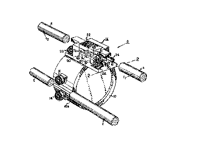
Figure 1, not drawn to scale, shows a movable lens arrangement on guide
rods according to the present invention.
Figure 2, not drawn to scale, shows a cross-sectional view of the guide rod
and the permanent magnetic assembly along lines 2-2 in Figure 1.
BRIEF DESCRIPTION OF THE INVENTION
Figure 1 shows a movable lens assembly 2 arranged on guide rods 4 and 6.
In one embodiment, the guide rods 4 and 6 are two hardened steel rods.
The movable lens assembly 2 includes a lens cell 10 having a perimeter l0a
with permanent magnet assembly 12 arranged thereon at the top of the lens cell
10 as
shown. A pre-load bearing 14 and guide bearing 16 are also arranged on the
perimeter l0a
of the lens cell 10 at a 90° angle with respect to the permanent
magnetic assembly 12. The
pre-load bearing 14 and guide bearing 16 cooperate with the guide rod 6 to
further support
and position the lens cell 10 along the guide rod 4.
The permanent magnet assembly 12 has a permanent magnet 20 which
provides a closed-coupled attractive magnetic force to support the lens
assembly 2

Patent
PDy292003
fesably, the less cell 10 is s~u~d against sh~c~ that ~ ~acceed
20 the close-coupled rnagrscdc attrae~t~tt forces fl and f2 by means of a
~le~ac~c,~
aperata~re 3U passing through the assetrably (nonrnagmetic i.e, leans cell) ~.
Z'he
d

:~. ~? ~ ~~ ~3 ~ .
~t
~~..z~ao~
these filled io tho a~ ~ritilc~us ' ~ fr~am tlt~ spirit ~d
of the 3nvea~~icm
which is liariit~tt cnty Op then follow clair~as end 1~ imterpa~~~n thereof.
,,

Representative Drawing
A single figure which represents the drawing illustrating the invention.
Administrative Status

2024-08-01:As part of the Next Generation Patents (NGP) transition, the Canadian Patents Database (CPD) now contains a more detailed Event History, which replicates the Event Log of our new back-office solution.

Please note that "Inactive:" events refers to events no longer in use in our new back-office solution.

For a clearer understanding of the status of the application/patent presented on this page, the site Disclaimer , as well as the definitions for Patent , Event History , Maintenance Fee  and Payment History  should be consulted.

Event History

Description Date
Inactive: IPC from MCD 2006-03-11
Time Limit for Reversal Expired 2005-04-11
Letter Sent 2004-04-13
Grant by Issuance 1999-09-28
Inactive: Cover page published 1999-09-27
Inactive: Received pages at allowance 1999-07-06
Pre-grant 1999-07-06
Inactive: Final fee received 1999-07-06
Notice of Allowance is Issued 1999-01-15
Letter Sent 1999-01-15
Inactive: Approved for allowance (AFA) 1998-12-21
Amendment Received - Voluntary Amendment 1998-11-27
Inactive: Multiple transfers 1998-09-09
Inactive: S.30(2) Rules - Examiner requisition 1998-05-29
Inactive: Status info is complete as of Log entry date 1998-03-31
Inactive: Application prosecuted on TS as of Log entry date 1998-03-31
Application Published (Open to Public Inspection) 1994-10-13
All Requirements for Examination Determined Compliant 1994-04-11
Request for Examination Requirements Determined Compliant 1994-04-11

Abandonment History

There is no abandonment history.

Maintenance Fee

The last payment was received on 1999-03-24

Note : If the full payment has not been received on or before the date indicated, a further fee may be required which may be one of the following

  • the reinstatement fee;
  • the late payment fee; or
  • additional fee to reverse deemed expiry.

Patent fees are adjusted on the 1st of January every year. The amounts above are the current amounts if received by December 31 of the current year.
Please refer to the CIPO Patent Fees web page to see all current fee amounts.

Fee History

Fee Type Anniversary Year Due Date Paid Date
Request for examination - standard 1994-04-11
MF (application, 4th anniv.) - standard 04 1998-04-14 1998-03-20
Registration of a document 1998-09-09
MF (application, 5th anniv.) - standard 05 1999-04-12 1999-03-24
Final fee - standard 1999-07-06
MF (patent, 6th anniv.) - standard 2000-04-11 2000-03-15
MF (patent, 7th anniv.) - standard 2001-04-11 2001-03-14
MF (patent, 8th anniv.) - standard 2002-04-11 2002-03-13
MF (patent, 9th anniv.) - standard 2003-04-11 2003-03-12
Owners on Record

Note: Records showing the ownership history in alphabetical order.

Current Owners on Record
RAYTHEON COMPANY
Past Owners on Record
GABOR DEVENYI
Past Owners that do not appear in the "Owners on Record" listing will appear in other documentation within the application.
Documents

To view selected files, please enter reCAPTCHA code :


To view images, click a link in the Document Description column (Temporarily unavailable). To download the documents, select one or more checkboxes in the first column and then click the "Download Selected in PDF format (Zip Archive)" or the "Download Selected as Single PDF" button.

List of published and non-published patent-specific documents on the CPD .

If you have any difficulty accessing content, you can call the Client Service Centre at 1-866-997-1936 or send them an e-mail at CIPO Client Service Centre.

({010=All Documents, 020=As Filed, 030=As Open to Public Inspection, 040=At Issuance, 050=Examination, 060=Incoming Correspondence, 070=Miscellaneous, 080=Outgoing Correspondence, 090=Payment})


Document
Description 
Date
(yyyy-mm-dd) 
Number of pages   Size of Image (KB) 
Description 1998-11-26 5 224
Claims 1998-11-26 2 61
Claims 1995-04-13 4 154
Abstract 1995-04-13 1 34
Drawings 1995-04-13 2 83
Description 1995-04-13 5 221
Abstract 1999-07-05 1 23
Representative drawing 1998-08-18 1 30
Representative drawing 1999-09-20 1 16
Commissioner's Notice - Application Found Allowable 1999-01-14 1 163
Maintenance Fee Notice 2004-06-07 1 173
Correspondence 1998-06-01 1 24
Correspondence 1999-07-05 2 75
Correspondence 1999-01-14 1 35
Fees 1997-03-19 1 56
Fees 1996-03-20 1 57