Note: Descriptions are shown in the official language in which they were submitted.
-" 2121021
A~torney Docket LBT 2-140-3
MODULAR FLOOR SUB-STRUCI URE FOR Tl-IE
OPERAT~ONAL SUPPORT OF COMPUTER SYSTEMS
Ba~ uulld of the lu~,n~io
Tl . I;(io~ y~ indus~i~1 data centers have been clecign~d to accommodate relatively
I() large ".l~ lrla lle" ccIllpliter systems. These systems include stand-alone hinged cabille~
conta;ned control processing units, tape guide systems, disk drives, printers, control
cc as ~1~ s and the like. When aissel-lbled within a data center, the systems have required a
- relatively larger amount of floor area within a given building, as well as a carefully
controlled enviro..l.lent. Control over that e.l~dlol~ ellt requires a dedicated, sealed
15 CC~ Jt~ ~ room which is serviced by c(JIl~oh.l;ng de~ d air-con~ ioning systems. In
similar fashion, critical e~p~ nt within the room is serviced by de~lir:tted Ullillt~,.l u~lible
power sUppli~s Because of the extensive amount of electrical h~ ection required
~ ~ both forpower supply and system co---n-~ these COII~I~UIGI rooms typically contain
- ~ raised aoors forrned of tiles su~ult~,d upon frames beneath which the complex cable
20 rl~,t~ ks can be laid. Generally, the provision of such colllpu~ rooms has IG~lesented a
srb I f!_ 1 Li~ ~llllent on the part of the user.
Over the recent past, the co...l-u~ ' industry has introduced processing systemse ~ ~ u~g more modem, modiular eleclliunics and s.,ppo- Lh~g c~ll-pone.lts permitting their
raick mounted i- c~ Such ~liodiul~ designs provide for s~ 1 flexibility in
25 .linco~ odating for varying ~ ing cl~m~n~lc For example, these systems readily are
df d inclG.Ile.~ ly as the growth of ~ locess;ng nee~s on the part of the user increases.
As a conY~u~ nce of i..l~llo.~,d design, such systems exhibit lower heat loads, lower noise
output, and a co~.~p~ . P s~ in pacl~ging such that they are plullloted for installation within
the e..~ un~ucnt of a b~s;n~ss office as opposed to a data center. One such system, for
30 e ~ , is i~l~n~ d under the tl~ "AS/400", 1l~ ed by Inlc.l.a~ional Business
Machines Cûrporation~ is system offers a family of processor related modular units
generally employing rack-mounted pncL-aging Cabinetry carrying the rack mounted
m~--l~s will, for eY~mrl~, have nominal dimensions of 26 inches width by 36 inches
depth, and 62 inches height To faciUtate their delivery to an inlended operaling localion,
35 they are SU~ ,d for movement UpOIl casters. With the racks fully loaded, the eqllipment
may, for example, exhibit a he,lt load of 11,000 BTUs per hour, representing a demalld for
2121021
about one ton of air-conditionillg. Similarly, the units will c~all for an ullinterrllptcd power
supply load capacity of about 3KVA. These re~uh~ ellts, particularly whell more than
one colllponcnt of a system is utilized (a typical case) generally cannot be accommodated by
the in-place air-conditioning system of a building nor its in-place power c:~r~bilities Thus,
S the user is called upon to find a technique of butll.,s~iug air-conditiolling capacities, as well
as power feeder inputs. Additionally, to ?cc-J"",~date for anticipated growth incl~llle"ls in
such systems, in keeping with that aspect of the system design, the user must anticipate
future air-conditioning needs, as well as future uninterruptible power supply needs. The
result, in general, has been a resort on the part of the user to a conventional sealed
10 C~II~IJL' room, an approach whicll essçn~ ly colllplumises many of the advantages of
this modular form of processing system. Such Colll~)ut~,l room inct~ ions further may be
called for where the of fice facilities within which the systems are installed are leased. Very
often, the owners of such leased facilities will substantially shut-down building air-
con~ ioninv systems over weekends and the like much to the detriment of the data center.
15 Thus, a dedicated environment is necesci~t~ Further, where computer rooms areinct:llled within leased facilities, those dedicated rooms become fixtures and, without
a~ ,nt olh.,lw;~e, cannot be ~ rd and llalls~)oll~d to a new installation site.
As is apparent, the full adl, v and flexibility of these newer modular computer
systems can be recognized only when a coll~onding flexible, modular support of their
20 ell~ilu"..~ 1 and power input demands can be achieved on a practical cost basis.
Summary
The present invention is ald.e,ss~d to a floor supported sub-~llu~;lul~; system and
module ~csemb!~,~e serving to operationally support computer system components,
25 particularly of Lhe in~ e.llally ~ r ~ ~e, rack mounted variety. Floor sub-structure
ac5~ ~~hl~ges of the invention are formed of inte~Qr-~ cA uniformly ~ n~;orled floor
mo~ s~ each with a frame with sides e~ nrling from a bottom surface to an upper portion
or edge. This edge supports an upwardly disposed support surface. Two square floor tiles
are carried at the upwardly disposed support surface by each module such that each defines
30 an internal chamber. The internal chamber of select ones of the floor module challlhv~
contain modular operational support devices for de~licat: ~ use by corresponding computer
co..~po~ u~ In this regard, air cooling coils and ~Csoci~t~d motor driven blower fans are
in~t~ A in certain of the floor mo~ es The cooling coils within-those modules are
d~Ci~gl e~ to accommod~. îhe heat load of one collll,ut~,. component. Because of the
35 I~ ;ti~c region of cool air flow utilized within the modular assemblage, and the lower
heat loads involved with this form of co. ~ ~p.,t~ ~ co. ~ olle .t, these coils may be designed to
avoid vapor conden~-ion for most installations. Uninterruptible power supply (UPS)
devices are positioned with the confines of the internal cavities of other select floor
modules. These UPS devices are provided with a limited power capacity which is
-2~
~: :
~-' 2~21~21
dc(licated to the rcquiremellts of nn associated computcr component. Still others of the
floor modules are formed having a power distribution network mounted therein. These
networks are designed, for example, to provide circuit breaker protected inputs for, for
example, up to five UPS devices, or a computer component where those devices are not
5 utilized. The networks also provide a source of power for a corresponding five blower fan
motors and any ~ssoci~ted condensalioll collection pumps
Interconnection between adjacent floor modules is by bolting together adjacent
upwardly disposed regions of side portions of the modules. Leveling of the modules is
carried out through the use of noor engaging foot slluclules whicll, in one cmbodiment
10 permitting very low elevated floor heights provides a capability for retracting these foot
modules entirely within the cavities of the modules themselves. For tlle latter embodiment,
elevated aoor heights as low as, for example, about 10 inches are achievable. To direct air
flow from the blower structures to outlets within other modules directed into the lower
regions of the co~ ,ulur system eolllponc.ll~, panel openings are formed within the sides of
15 the modl-les These panel openings may be selectively blocked to define air flow patlls.
In another embodiment of the invention, the modules are formed witll floor
engaging foot 51iuClul~,S e~n-lin~ below the bottom surface thereof and which are not
retractable to the diserete cavities of each such module. This results in a cost benefit but a
slightly higher elevated aoor surface. Preferably utilized with the module assemblage is a
20 step structure ~ulluun~ing one or more sides of an ~sse ..tl~ge of modules. By positioning
those modllles earrying cooling eoils adjaeent sueh outer side of the assemblage, the
interior of the modular step ~t u,_lul.,s ean be employed to retain conduits carrying cooling
fluids as well as any eolleeted con-lenc~e from eoils. This provides an advantageous
separadon of power ~lic~ibution eabling from the eonduits earrying fluid. In general, the
25 cond i~c for earrying cooling water and the eabling for electrical distribution may be
d, through the panel o~ng~ within the sides of the morlul~.s
In a ~ full~d c .nbo~li-n~ t of the invendon, a step structure is udlized along a linear
portion of an ~Se~hlqge of the aoor moclllles This step structure includes the noted step
cavity for carrying cooling conduits but ~ itjon~lly has a step defining structure. The step
30 defining stluelul~i is pivotally movable between a seated position and an open position to
gain aceess to the side of the floor module to which it is ~ hecl These aoor modules are
the acdve ones in(~ g the cooiing coil with exposed and now accessible Ihe.ll.osl~t and
CC~-A lin~ for movement of coolant fluid; the acdve accessible co~ onen~s of a power
U '--- network such as cireuit breakers; and the readouts and manual input controls of
35 an uninterrupdble power supply. Access to these co.nl~onel-ls now becomes quite facile to
service p~-~ol~llel
In another preferred arrangement of the invention, that floor module which
h~cOI~ulates an unintemlptible power supply which is located adjacent the noted step
st uclu.e employs a UPS arrangement incorporating a self-contained cooling r."u rllen.
-3- -
~:
y
' 2121021
.~
Ihc tloor module containin~ UPS dcvicc is structured sucll that the UPS system is sclf-
cooling and, in fact, its air flow path providing such cooling is isolatcd from the air flow
patl- developed from the cooling coil containing floor module. Witll such an arrangelnent,
should power be lost, then even thougll air circulation blower associated with the cooling
5 coil is not working, the UPS system, now on battery power supply, will remain itself
cooled pending orderly shut-down of the supported computer system. For this
arrangement, the step structurc is designed to provide an air transfer opening with an air
transferability extent at least equivalent with the air input geometry of the UPS devicc.
Movement of the caster mounted coulplllel system components on and off of Ihe
10 SU~ u~ ut iS provided through the use of a ramp assembly formed of two folding ramps
which may advantageously be stored within an empty floor module. Additionally, floor
modnlçs may be utilized to support an envi.u.~ Gntal confinement enclosure where the
systems are c~ lo~Gd in rigorous factory e.l~ilolllnGIlts or where it is desired to employ a
Halon based form of fire protection. By utilizing the restrictive enclosures, the amollllt of
15 Halon required is held to an en~ .,...G.~ ly advantageous minimnrn
The invention, accordingly, comprises the system and apparatus possessing tlle
collstlu~;Lion, CO~ ;on of ck-." "1~, and arrangement of parts which are exemplified in
thefollowingdetailed-li.cclo.~c.
For a fuller undG.~I-n~ of the nature and objects of the invention, reference
20 should be made to the following detailed description takcn in conneclioll Wi~ he
~C~ yillg ~awillE,S.
Brief Des. ~ ;I)lio~ of the Drawings
Fig. 1 is a pictorial ~ ,..,se..l~tion of a system employing an assemblage of floor
modules accol li-lg to the il.~rertion and sul,l,o,ling two colllllut~,l system componen~s, one
being shown in ~ to reveal floor struct~lring;
Fig. 2 is a pel~cli~ view of the frame components of a floor module as may be
, IG,~ with the acs~-.-hla~,v shown in Fig. I;
Fig. 3 is a- plan view of the aoor assembly shown in Fig. 1 with portions removed
andbrokenawaytorevealinternal ~huclulc, :
Fig. 4 is a se.,lional view taken through the plane 4-4 in Fig. 3;
Fig. S is a secdonql view taken through the plane 5-5 shown in Fig. 3;
Fig. 6 is a partial s~ ~~ ~~' view taken through the plane ~6 shown in Fig. 3;
Fig. 7 is a pc.~ e view of the system of Fig. 1 showing employment of a ramp
~ .clulc for moving compute~ system coll-ponents to and from ~he floor module
~c~ e~
Fig. 8 is a pardal sec~ional view taken through the plane 8-8 shown in Fig. 7;
Fig. 9 is a top view of a system according to the invention showing an assemblage
of floor modules with çnh~nced support cc,~ ,onelll access;
-4-
~ 121~21
Fi~. 10 is another top vicw Or an assemblage of floor modllles according to the
invention showing the flexibility thereof to accommodate for varying available facility
areas;
Fig. I l is a pictorial vicw of another entbodiment of the invention showillg thc
S floor module ~cemb~oge formed in COIut lt;on with a step ~ ~ tClu~c;
Fig. 12 is a an exploded pcl~.l,eulive view showing a floor module frame structure
and associated step tllU~;IUl~,S employed with the embodiment of Fig; 11;
Fig. 13 is a partial sectional view taken through the plane 13-13 shown in Fig. 11;
Fig. 14 is a top view of a floor module shown in Fig. 13 and additionally showing
10 alternate blower fan ~"ie.lt~liorl~.,
Fig. 15 is a partial sectional view of a floor module assemblage described in
connection with rig. 1 1 showing an alternate h~ lllo lule insert arrangement;
Fig. 16 is a top view of a floor module ~sçmhl~ge and associated step structure
according to the invention schematically showing the positioning of fluid carrying condllits
15 and power di ~llilJuli(Jn conduil~
Fig. 17 is a pictorial ~ ,sellta~ion of an embodiment of the system of the invention
showing a floor module assemblage in combination with an envil~JIllll.,.~tal confinement
e,nclG tUlC,
Fig. 18 is a pictorial representation of a system employing an assemblage of floor
20 modules according to a preferred embodiment of the invention, incorporating a step
.1. u~;luu~; with service p~ .vn-lel access features;
Fig. 19 is a p~ ,ecl;~, view of the frame co"~ponents of a floor module as may be
ell~plo~l with the ~ hl~g". shown in Fig. 18;
Fig. 20 is a partial sectional view of a floor tile support arrangement employed with
25 the frame co~q~ol~r ~1~ of Fig. 19;
Fig. 21 is a scction~ ' view taken through the plane 21-21 shown in Fig. 18;
Fig. 22 is an exploded pe~ e view showing a step ~t~ u~ employed with the
~ci~ ge of Fig. 18; and
Fig. 23 is a section~l view taken through the plane 23-23 in Fig. 18.
Detailed D~ sc~ ;I.ti-)n of the lu~l~,ulion
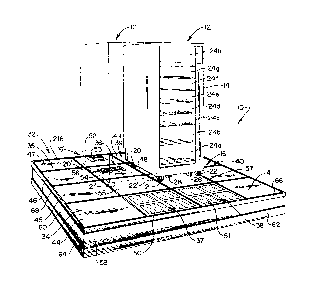
Referring to Pig. 1, the floor ~uppo~. d sub-~lluclu,~ system of the invention is
revealed generally at 10. System 10 as depicled, repl~sents a somewhat minim~l
configuration for use in the heat removal and power input support of a component of a
cc.. ~put~ - system, for ~ ~ I 'e, as ~ ,;,e.~t~ at 12. ('b,ul)O~lf ~1 12 iS of a rack mounted
variety, having an upright housing 14 ~u~lpolled from a base region as lepl~,sented ~ ;
generally at 16 which, in turn, is ~upl,~,n~,d upon rolling wheels or casters at each corner
thereof, three of which are l~ S ~ at 20-22. Within the housing 14 are a sequence of
pull-out racks 24a-24h which may be pulled out in the manner of a drawer by a~tending
~ ~
' -' 212102~
personnel. To avoid causing the component 12 to tilt forwardly wllen one or more racks
24a-24h are pulled out, an L-shaped forward brace (not shown) is attached to ~he housing
14 at brackets 26 and 28 following the positioning of housing 14 upon system 10. The
base region 16 of the device 12 is rectangular and has a nominal dimension of 26 inches in
5 width, 36 inehes in depth, and 62 inches in height. For the arrangement shown, the
system 10 is Acsembled to provide support to two adjacently disposed such components
12, the next adjacent eomponent being represented in outline fashion and in phantom at 12'
as being supported upon easters 20'-22' and having a base region 16'. Components 12
and 12' preferably perform in eonjunetion with an uninterruptible power supply (UPS)
I() whieh, in turn, reeeives a utility power input from a feeder line and a distribution network
which is circuit breaker ~)-otected. These devices may, for example, present a heat load of
about 11,000 BTUs per hour to the en~ ,..t within which they are operating.
System 10 permits the coll.ponents 12 and 12' to be used as originally intended,i.e. within an office envir~ ,nt without requiring the revision of the air conditioning
15 system thereof and without requiring the ~l~n;ul~ nt of the UPS system having capacities
A~ e~t for future expansion.
Fig. 1 reveals that components 12 and/or 12' are supported upon an elevated floor
,1. e ~ generally at 32 which is formed of an ~cce.,.l-l~ge of eight floor modules seen
in Figs. 1 and 3 at 34-41. While each of the modules 34-41 is formed having a frame
20 co---~ of s~lda-~liL~ h-.n~. on and shape, eertain of them will contain conditioners
for air sueh as ehilled water eooling coils or the like which are mounted, for example in
modules 37 and 38, as well as UPS systems as are located within modules 36 and 39 in the
system of Figs. 1 and 3. Eaeh of the m~ s 34-40 is formed to support two rigid floor
tiles which, for example, may be for a variety e.-l~ ed within conventional computer
25 room false floors. Generally, these floor tiles will be 24 inches square in dimension. Two
such f1oor dles, for eY~mrle those provided in eonjunetion with module 34, are seen at 44
and 45. Similar, eontiguous tiles are provided in eonjunetion with modules 40 and 41.
IIo,.~,~er, modules 37 and 38, in addition to eonventional tiles 55 and 57, will be seen to
eontain sueh tiles as are shown at 50 and 51, each carrying a pattern of air entry holes or
30 openings providing for an air input to the cooling coils immçrli~tely thelebenealln Floor
modllLos 36 and 39, in addition to providing a portion of the support for respective
ec,..~ r~ 12 and 12' also eontain a eompaet uninterrupdble power supply essentially
- e~ c .~ g about one-halfof their:e~ wise ~ on Accordingly, tiles such as
that shown at 52 in the ease of floor module 36 are eonfigured having a door opening 53
35 whieh provides eonvenient aeeess for the operator to observe UPS readouts such as status
as to whether the devices are under battery drive or utility drive, and the current power load
being imrosed The ~jaGent tile 54 within floor module 52 contains an air outlet 56
through which cooled air may flow into an appropriate base region of the computer
co...l.one ~t 12'. An identical arr,lngement is provided with respecmo complller componcll
-6-
2121021
12 as provided from floor modulc 39. Thc outer exposed sides of the assemblage of
system 10 are covered with a side panel or fascia, two of which are scen at 58 and 60 in
Fig. 1. Additionally, extendi-lg up from the floor level for the exposed sides of the
asse~llblage are polymeric baseboards, two of which are shown at 62 and 64. In similar
fashion, the upper edges of the sides of the assemblage are covered Witll a kick panel
formed of a polymeric material, two of which are seen in Fig. I at 66 and 68.
With the arrangement thus shown, the components, for example as at 12 and 12'
may be placed within a conventional of fice environment and will be supplied with adequate
cooled air for heat removal, distributc~ power, and, where desired, an unillterrllpted power
supply. No colllyut~r room constmction is required. In general, a cooling arrangement
within one module is designed to provide the capacity for one such component 12. The
UPS systems are similarly designed for d~icated use with one colllponc.~t. Thus, it may
be observed that the modular system readily grows with inclt;lllental growth of the overall
facility. The height of the elevated floor 32 for the embodiment shown may be as minimal
as about 10 inches, a height generally representing a step height. Preferably, the
acsemblage represented by system 10 will provide for adequate floor space to perrnit
p.,.~ol-nel access to the colllponc.lls as at 12 and 12'. For some installations, it further may
be des-l '' that the components 12 or 12' rest upon floor tiles which need not be removed
for mqir~P.nance access to support devices and systems contained within the modules.
However, the "footprint" or square footage demanded by the system illustrated is so
corlvenienlly small as to perrnit its use within facilities having more restricted area
availability. In this regard, for the example shown in Figs. I and 3, the entire in~talla~tjon
has a ~ootl,lint dilllel-sion of about 8' x 8'. Of advantage in addition to the mofll~larity and
y, the system 10 easily is removed from one facility or building to another and
does not c~ le a fixture.
Looking to Fig. 2, one e.llbodi for the &ame c~ one ~t of a floor module is
e~ ,sentcd generally at 80. Formed, for example, of sheet steel which is welded to
achieve the configuration shown, the frame collll,onc,.ll80is seen to have a lower portion
,se-~l~ generally at 82 which is supported upon the floor and includes a rectangular
co~tin~lon~ bottom surface 84 do~ w~udly from the corners of which floor engiqging
adjustable foot colll~Jolle.lt~ are provided. Three of these colll~ollenl~ are shown at 86-88,
while the upward portion of the fourth thereof is seen at 89. FYtentling upwardly from the
bottom 84 are side portions provided as panels 90-93. A single, rather large rectangular
opening is formed within the end or shorter side panels 90 and 92 as represented,
~ e~ ,ly, at 96 and 97. In similar fashion, lengthwise panel 91 is seen to have two
spaced-apart op~ 98 and 99 forrned therein and oppositely disposed parallel side pabèl
93 is formed having l~cl~-.g~ openings 100 and 101 arranged in aligning symmetry with
respect to openings 98 and 99. Panels 90-93 extend to respective top edges 104-107
wlle..,~.~,on they are bent to extend outwardly and upwardly to develop a connector flange
-7-
-~ 212102~
slruclure form of floor tile suppot rcpresented in general at 110 and having upstanding
connector flanges 112-115. Spaced connector holes are seen located within these
connector flanges 112- 115 which aue used to receive floor module interconnecting nllt and
bolt assemblies. Positioned between the upper panel edges 105 and 107 is a cross-over
support 118 which is used not only to provide structural support for panels 91 and 93, but
also to serve as a rest for one edge of each floor tile of the two such floor tiles utilized with
each module. The floor tilcs, not shown, which are positioned over the connector flange
structure 110, in general, mutually abut over the cross-over support 18. To improve their
noise free positioning, a thill elastomeric gasket (not sl-own) may be positioned over the
holi20ntal offset portions ey~en~ling outwardly from top edges 104-107. Small holes are
provided in conjunction with each of the openin~.c 96-101 for the purpose of receiving
machine screws holding sheet metal panels which serve to selectively close off these
openings depen~ling upon the form of air path desired within such systems as at 10. In
effect, each of the modules as at 80 provides a discrete cavity therewithin as represenled
15 generally at 120.
Referring to Fig. 3, typical uses for such cavities as at 120 are revealed. In the
figure, the floor tiles 51 and 57 are seen to be removed from module 38 to reveal an air
cooling ~l~g~ le.ll. In this regard, note that an air filter 122 is shown in broken away
fashion to reveal a cooling coil 124 po~;l;ol~P~ imme li~-ely beneath it. For the embodiment
20 shown and for in~t~ ionS generally ç~-~o~ ,d, the type of cooling provided by coil 124
is based upon chilled water or appropriate fluid. Thus, conrllliting is er~çn(led to the coil
124 as ~ ,sented by conduit 126 çY~n~lin~ to a T connection 128 which, in turn, is
coupled to a feeder input 130 which, typically, will be connected to an externally disposed
(outdoor) chiller colll~,onent. Line 130 also is seen to extend into floor module 36 for
25 pul~Joses of providing chilled water to a similar air cooling coil within adjacent floor
module 37. Return water from the coil 124 is provided through conduit 132 which, in
turn, extends to T 134 and to output line 136. Line 136 extends to a waste water disposal
outlet within the building within which system 10 is inct~ll~l Line 136 also provides the
similar return function with respect to the cooling coil of module 37. Control over chilled
30 water input to the coil 124 for the instant elllboLm~,nt is provided by a relatively simple
vacuum or p~ ic~lly based valve l~ sented generally at 138 which is located within
the cavity 140 of floor module 38 in co...bi~ ion with filter 122 and coil 124. Because of
the reladvely small Q ~ m~ lirf~l r e between the cooled air from coil 124 and ambient
air t~ , a simple control of this nature becomes available. Tmm~A cly beneath the
valve 138 within cavity 140 is a flexible hose 142 which extends from a condensate pump
144 outwardly from the system 10 for disposal as waste water. A similar flexible hose
146 is seen e ~ ~ outwardly from the system. Hose 146 is associated with thc cooling
coil Illounted within floor module 37.
- 2121021
.
Also disposed within discrete cavity 140 of floor modul~ ~8 is an air blower fan148 which, in turn, is driven from an electric motor 150. By blocking the air transfer
openings, for example as described at 98, 99, 100 and 101 in Fig. 2, as tl-ey arc provided
at floor module 38 as well as blocking the opening, for example corresponding to opening
96 in Fig. 2 adjacent coil 124 and inserting appropriate gaskets, the input of blower 148
will cs~ l. an air flow path extending through the openings within floor tile 51 (Fig. l ),
thence through the coil 124 to Ihe input of blower 150 and thellce as pressuriz~d from the
output thereof to exit through the mutually disposed panel openings at the abutting juncture
of floor modules 38 and 39. To further define the air flow path, the corresponding panel
openings of floor module 39 are blocked such that the discrete chamber 152 thereof
becomes a plenum and cooled air may exit thrwgh an opening therein formed identically to
that shown at 56 in floor tile 54. The blowers as at 148 may provide, as a minimllm, about
450 cubic feet per minute of air movement. In addition to the panel openings at the
elongate sides of floor module 39 beiing closed, the discrete cavity 152 of module 39 also
contains an unillt~ u~ le power supply (UPS) 154 which, preferably, is of a capaci~y
wherein it is dc~ ~ to the co-l-~)uler system component 12. In this regard, the device
154 may have a capacity, for e~ , of 3 KVA. As noted in connection with module 36,
UPS 154 has an upwardly disposed switching and readout panel 156 which is located
direcdy beneath an access door as described at 53 in conjunction with tile 52.
Floor module 40 is bolted to floor module 39 along adjacent portions of their
con~ t~!l flange Shu~ ,S as des. ~ d in connection with Fig. 2. Module 40 is provided
having a power distribution network 160 forrned within the discrete cavity 162 thereof.
The network 160 is coupled to the utility feeder inputs, for example, ~ ,serlted at cable
164 and provides a circuit breaker function including circuit breakers 166 and plug
cc. --.f~t.~ oudets l~ - d generally at 168. T~hese outlets at 168 provide discrete power
inputs as shown at cables 170 and 172 to the UPS cc,lllponenls within respective floor
modules 39 and 36. ~d~ on~lly~ power is supplied, as l~ ,se~ d at lines 174 and 176,
to the fan motors within respective floor modules 38 and 37. One distribution network as
at 160, with 100 arnpere service, in general may serve up to six colll~)ulel collll)onellts, for
exarnple e.ll~lby;ng h ~ - ~ UPS colllpolle~.ts, conden~ion pumps, and blower drive
motors. Thus, one main breaker and seven branch breakers are employed with the unit. In
the latter regard, six of the breakers are opc,.ationally ~c~oci~ed with cc~ )ute~ ccnll~Jonenls
while one such breaker services all fan and cond~ ~ c ~ ~ ;o~ pump motors utilized.
Certain of the tloor modules of the system 10 serve a storage function retainingservicing tools and the like. For the system shown at 10, such a function is assigned to
floor module 41 which is bolted at abutting flange conncclol assemblies adjacent modules
38 and 40. The discrete cavity 180 of module 41 is seen to contain a ramp ilssemblage
formed of two ramps 182 and 184 which, in turn, are formed of hinged rnmp lllenlbel~
which may be folded as depicted to fit within the confines of cavily 180 and benea~h, for
g . . :
- 2121021
example, the cross-over suppor~ g member 186. Also contained in tlle cavity 180 is a
socket wrench 188 which is employed for adjusting the floor engaging foot Go~ uonellts as
described in conneclioll with Fig. 2 at 86-89. Certain of these foot components are seen in
Fig. 3, for example, at 190 at the four corners of each of the floor modules. Modules 36
S and 37 are conl-ect~,d to and abut against coll~,s~.ol1dillg respective modules 39 and 38, and
are selected having identical functions for su~,l,olling colllpute- systen- cc,lllponellt 12'.
Referring to Fig. 4, the al-,hite~;lul~ involving the connecting of two modules 36
and 37 together is revealed in sectional detail. Note that the abutting l-ps~n-ling connector
flanges 200 and 202 of respective floor modules 36 and 37 are bolted together as~,plcse.lted by bolt conne.,lol 204. Flanges 200 and 202 correspond with those described
at 112 and 114 in Fig. 2, three bolted connections being employed. When so connected,
the adjacent side panels shown respectively at 206 and 208 are spaced apart to define a gap
between the abutting floor modules 36 and 37. This ~llu~lu.hlg developed from the offset
nature of the connector flange assembly facilitates the leveling of modules 36 and 37 to
achieve a level floor surface 32. It additionally may be observed thal the connector
~u~;lu~,S acco,l~",od for the shape of the floor tiles. Note in this regard that floor tiles
54 and 55 mutually abut over the upst~nrling flanges 200 and 202. To achieve this
abutment, it may be o~s~ ,d that the p~ .h~.. ;"5 of all of the floor tiles are forrned having
double offsets, one offset serving for the instant embodiment as the connective or abutting
surface for load tr~ncmicsion~ while the next offset surface eytçn~ling to an u~pe.
abutting edge. At the center of the floor mo~ es, the floor tiles rest upon a cross-over
support as earlier-~escribed in connf~ction with Fig. 2 at 118. Such cross-over supports are
shown at 212 and 214 in conn~ ~;on with respective floor modules 36 and 37. As before,
the abutting edges of the floor tiles are in mutual contact, while the lower offset suppo- lhlg
surfaces rest upon supports as at 212 and 214. At the outside edges of the system 10, the
outer abutting edges of the tiles, for example tiles 50 and 52, are covered by kick panel 66
in the case of tile 50 and 216 in the ease of tile 52.
Looking to the opc.aliol1al COml~ol~ent~ and their ~ccoci~ion within the paired floor
mod~ os 36 and 37, the discrete cavity 218 of floor module 37 is seen to incc,.~,o.dte the
cooling coil 220 of an air chiller system. Above coil 220 is a filter which is located
_ ' 'y beneath floor tile 50. Floor tile 50 inco.~,u ~ a plurality of air duct openings
~,pr~sented at 224. l~....f.l at~.ly beneath the coil 220 is a condenc~te colleetion pan 226
whieh is s1anted dO..ll~.a~ly to provide a cl ~dc--c~te receiving region 228 within which a
con-~nC~e pump 230 is loeated. Concerning the presence of condçnc~tion, coil 22035 preferably is d~ C;~ f d such that only a minimal occasion for co~-dc nc~l ion deiclû~ ,nt is
present. In this regard, the range of incoming fluid temperatures to the coil will be from,
fo m . l le, 45-F to as high as 60-F. In designing the coil, an operational envelope is
chosen with respect to the number of rows and area of the coil that, for essentially most
room conditions, the coil will remain dry. However, in certain geographic areas, the
-10-
-'-" 2121021
hulllidity levels are so higll that tl-e condensate pan 226 will be lltilized. In general, the
pump 230 is arranged to turn on wl-en a float actuated switcll thereill rcsponds to about
0.75 inch of water within the region 228.
Positioned forwardly within the discrete chamber 218 of floor module 37 is a
blower fan 232 having an input at 234 and an output at 236. Driven by an electric motor
(not shown), similar to that described at 150 in Fig. 3, the fan 232 establishes an air flow
path as r~l-,sented by the arrows in the drawing. In this regard, air is drawn through the
air duct openings 224 of floor tile 50 as r~,pl~,sented at arrows 240 and thence through tlle
filter 222 and cooling coil 220. Then, the air, as represented, for example at arrow 242,
enters the input of blower 234 and exits from the output 236 thereof as l~p.-,se.ll~d at arrow
244. Arrows 244 represent that the air is drawn through adjacent openings of the side
panels of floor modules 36 and 37 at the gap 210. To assure the integrity of this air path
for the present e.--bo(lillle.-l, elongate focll..aceous and elastu---.,.ic gaskets 246 and 248 are
positioned at the top and bottom of gap 210. The air then enters the discrete cavity 250 of
floor module 36 and exits, as le~,.esellted by arrow 252, through opening 56 in!o the
appropriate receiving base region of col..l)ùle~ system component 12'. Air blower and
motor co...hi~ iol~ also can be installed within a floor module to direct air outwardly from
a panel opening at an elongate module side.
The discrete cavity 250 of floor module 36 additionally includes a dedicated
Il.. h~t~.~u~t ' '- power supply (UPS) 254 having po-.~. input at cable 172 and a conditioned
output which is coupled to co-nl)onent 12', for example via cable 256 which extends
through dhe air oudet opening 56. Note, as ~~ se.~lt;d by arrow 258, that the arrangement
permits dhe flowing of air across the UPS device 254 to aid in heat removal thc.l;rlulll.
The air paths thus described are defined by g~ ing and the selective closure of
the panel op~u;.~ as earlier described at 96-101 in conn~ction with Fig. 2. In this regard,
thë euclosulc of the outside widthwise opening 260 of floor module 36 is by a thin sheet
metal panel cover 262 which is connected to the module by sheet metal screws. That
particular edge of the system 10 is considered to be unobservable being, for example,
positioned adjacent a wall or the like. The co..~,",ondingly opposite end of the30 a~ . for example opening 264 within floor module 37, is closed by side panel or
side fascia 58. Select ones of the intervening openings are closed with panels as at 262.
For ~ . 'e, these ol)e-~ will include those shown at 266 and 268 at floor module 37.
The oppositely disposed openings of module 37 also are covered in the same manner.
Ilo..~,.,er, to provide for the air path as ~ ;,ented at arrow 244, openings 270 and 272
remain uncovered. In the case of floor module 36, oull)o~.l openings 274 and 276 are
closed, ho..~ , the openings dis~,osed oppositely ~ ,ÇIoll. are open to pemlit air flow
toward a discrete cavity 162 of floor module 40 as des~-ribed in conjunction Witll Fig. 3.
This pemmits a mo-1icunn of heat removal with respect to that component. However, all
panel openings of the storage model 41 described in that figure are blocked.
I I
--" 212102~
Turning to Fig. 5, the interrelationship of the floor modules of system 10 again is
rcpresented. Note that the internal cavity 280 of outboard floor module 35 is enclosed on
one side by external panel 60 and the rem~ining openings thereof are closed by covers, for
example as at 282 and 284. Modules 35 and 36 are bolted together at their upstanding
S connector flanges to provide a coupling lcpl-,sGnt~d generally at 286. Note that opposite
cover 284, the discrete cavity 25() of floor module 36 is blocked by a cover 288 to define a
gap 290. No gaskets or the like are provided within the gap 290 inasmucll as no air path
defilnition is required. E;loor modllle 35 functions to provide access floor spacc ror the
users of the cO~ JUt-,~ center
The urst~n-ling flange components of floor modules 36 and 39, as they occur
loll~;n~ lly lh~,..,~t~.~n are bolted together to define a coupling represented generally at
292 providing a gap 294. Oppositely disposed side openings of modules 36 and 39 at gap
294 remain open and the air path therebetween is established by spaced foamaceous
cl~to.--~.ic gaskets 296 and 298. Similarly, the abutting upstanding flanges along the
coll~,s~,ollding longinJ~in~l edges of floor modules 39 and 40 are joined together at a
coupling l~ senled generally at 300 to define a gap 302. To provide for the earlier-noted
air flow about distribution network 160, the panel openings adjacent gap 302 are not
blocked and the air path thc~. be~ el1 further is defined by elastomeric foam gaskets 305
and 306. It may be observed that the gaskets at 305 and 306 or 296 and 298 as well as
those described in connectiQn with Fig. 4 permit movement between adjacently coupled
floor modules while still providing for the d~fini ion of air flow paths cQol air is directed to
co.ll~onen~ 12 through outlet 299 in floor tile 54. In general, the panel openings within the
entire pe.i~ y of the ~Cs~ e or system 10 will be blocked either by covers or fascia
boards, the latter being described, for eY~mple at 58 and 60. External panels are provided,
as shown in Fig. 4 at 262 or at Fig. S at 308. To provide for the pne. lllalic integrity of the
discrete cavity 162 of floor module 40 at the point of entry of cooling fluid and electrical
, udlity input, an external conduit port 312 may be included with such panels as at 306 The
upper kick panels generally are provided around the entire assemblage, one such side kick
panel being shown at 310 in Fig. 5.
Co~.c;~ g the leveling plocedul~ itself, l.,relence is made to Fig. 6 where one
;."e-l~ of a foot colllponent 190 of a leveling component, for example as used in
col~jul~clion with floor module 41, is displayed. Foot colllponent 190 is seen to include a
floor eng~ging lower foot 320 which is coupled to an elongate threaded stud 322 which
extends to an integrally formed hexagonal nut portion 324. Stud 322 is threadably engaged
within a threaded bearing block 326 which, in turn, is welded to a box-shaped steel support
,sented generally at 328 and welded to the bottom 330 and corner-defining sides of
module 41. Thus, employing an elongated wrench as at 188 as shown in Fig. 3, theinstaller may rotate the stud 322 from nut portion 324 to move the assemblagc 190
inwardly ~hrough an opening 332 formed within bottom surfacc 330. This arr,lngcmcllt
-12-
2121021
pcrmits the bottom surface of at Icast one of the floor modules to be yositioned directly
against the s~pl)o, ~ g floor to assure tllat the elevated floor surface 32 of thc assemblage
10 is at a miniml-m height, for cxitmple, about 10 inches. Where grcater elevated floor
surface heights are available, tl-en the foot 320 of the assemblies may be normally
S positioned below the bottom surface 330, an arrangement which is less expensive but
which pronnotes greater elcvated floor surface heights. For the latter applications, the
cavity defining structure 328 is replaced, for example, by a solid steel component wllich
may have a cross section wllich is round or rectangular depending upon the desires of the
user.
I() An advantage of the modular O~ .. ,k'aFe of c~ po,lents of the system 10 resides in
a capability for rearranging the floor modules depending upon changing processing
~uil~ e.lts and/or changes in the geometry of the floor region available for the data center
function. These alterations may require the movement of computer system components as
at 12 off of and on to the elevated floor surface 32. Because a using entity typically will
15 not have rigging e~lui~ ellt or the like to move these components about and only limited
storage capacity, the instant system provides the foldable ramp assemblage wllich has been
described as being storable within the discrete cavity of an otherwise "empty" floor module
as at 41. In general, the cc.,ll~onellts themselves are movable upon casters or wheels as
described in conjunction with Fig. 1, for example at 20-23. Additionally, the computer
system cc,.. l~,onenls 12 may have an ~-l~t~d ~ specified weight of about 1800pounds. ~ -r~ further l~o.~ that movement to the elevated noor surfaccs 32
be along an inclined ramp or the like having about a 1:8 inclination. Thus, for the nominal
2 ft. x 4 ft. size of the floor modules of the invention, a ramp pair is provided which is
foldable to fit within the lengthwise extent of a given floor module. Looking to Fig.7, the
racks 182 and 184 are shown op~ ionally positioned with respect to the system 10.
Acec.~lingly, the same nnmPr~ion plovided in the figures hel~,torolc; ~lescribe~ is supplied,
where appropriate, in the figure. These ramps are identically ~llu~;lul-,d, in this regard,
ramp 182 is formed of two upwardly facing channel lllc~ 340 and 342. Members 340and 342 are hingedly coupled together at a hinge 344 and one such member, for example
ramp member 340, is configured having two oppû~ilely disposed L-shaped brackets 346
and 348 e~ten-ling dO~ .a.dly ~14,~,rluu~. The outward flange of each of these L-shaped
' t- 346 and 348 is configured to threadably retain a foot assembly as sllown,
~,spccti./ely, at 350 and 352. ~cse~nhli~s 350 and 352 may be ~LIuclul~,d in the same
manner as the foot structure in~ e foot 320, threaded stud 322, and hex nut portion 324
d~s~ibed in connection with Fig. 6. That end of ramp member 342 opposite hinge 344 is,
in turn, pivotally coupled to channel shaped bridging member 354 at a hinge connection
356. Bridging member 354 is of a length serving to span over a removed floor tile which,
for the instant de..,o~ lion, would have been floor tile Sl as described in Fig. l. The
end of the bridging member 354 oppûsit~,ly disposed from hinge 356 is seen to rest upon
-13-
'
-' 212102~
Ihe next adjacent floor tile 57. Bridging member 354 additionally is coupled to a
downwardly depending flange engaging coupler ~ ,sented at 358 which serves to
stabilize the ramp 182.
Ramp 184 is iden~ic~lly structured, including ramp members 362 and 3G4 which areS hinged together at a hinge conllection 366. The extended ramp is supported at the hinge
connection 366 by assemblies fonned of L-shaped bracket members 368 and 370 which, in
turn, support floor çn~ing foot assemblies represented, respectively, at 372 and 374. As
,sent~ ~ lly in Fig. 8, a bridging member 376 is pivotally connected to one end
of ramp member 364 at hinge 378. As before, bridging member 376 spans the region10 enco.~ dssed by the necess~uily removed floor tile. A flange engaging coupler is provided,
as shown in general at 380, which is seen to be formed of downwardly depending bifurcate
members which extend over the llps~anding conncctc.l flange 382 (Fig. 8) as well as kick
panel 66. Ramps 182 and 184 are positioned so as to be aligned for the reception initially
of casters 21 and 22 and then casters 20 and 23 of colll~ut~l system col,lponent 12.
The configuration of Fig. 1 represents a somewhat minimal one for the purpose ofoperationally ~upl)ol~ g two COînputer system components as at 12 and 12'. With this
configuration, the accessing of ~upl)o~ lg floor modules containing equipment for
c~ndi1ioning air, or UPS systems requires that the collll)ut~,l system components be moved
to clear the appl~p region for floor tile removal and access. While the components for
20 co~J;~o~ g air and UPS systems have a high reliability and a collt;~onding long mean
time between failures, for many inc~ tionc it is desirable that the floor tiles over such
Cc~ o~ be removable without any re~uiu~ nt for le.ll~ ily relocating the computer
system CO~ i)nf ' l'; With the addition of only one empty floor module, such a feature is
acco...l licheA Referring to Fig. 9, an ~ssemblage of nine floor modules achievillg this
25 de;.il~blc aspect is revealed, in general, at 390. Assemblage 390 is seen to operationally
support two COI~ system co~ Gnls 392 and 394 in a manner wherein the floor
mod-lles beneath the cc,lllpo.lenl~ are empty, i.e. do not contain operation supporting
h~;~h~ s With the a~ "r n~ shown, a sequence of three floor modules 396-398
are coupled end to end as a linear array and against one side of this array there are
30 p~ d and co~ ,t~l a side-by-side array of six floor modules 400-405. Colu~onellts
392 and 394 are located over empty floor modules 401-404, those modules being
ct~u: -~ to this co...l-i~ ion only by gaskets and the select closure of panel openings as
dcs~;bed earlier. Posi~ioned outwardly and readily accessible through their associated
floor tiles, floor modules 397 and 398 are configured for developing conditioned air in the
35 same manner as mor~ s 37 and 38 ~~ ~,tof(JI~; described. The preferred direction for the
outlet of the air cil-iulation blowers within floor modules 397 and 398, respectively, is
,c.lt~ by the arrows 434 and 436. This is achieved by the relatively simple expedient
of turning the fan assemblage, for example motor 150 and blower 148 as shown in Fig. 3
by 90'. Similarly, floor module 396 is configured for retaining a power distributio
-14-
.
2121021
n~twork and is struclured identically as module 40 The power distribution network is
l~p.~sented in dashed form at 408 Air path development with modules 396-398 is
provided initially by the closurc of all panel openings about the outer periphery of the
assemblage 390 Additionally, the panel openings are blocked at the connecting sides of
the modules as represented at 410 and 412 Correspondingly, the panel openiIlgs are
closed at the abutting sides 414, 416, and 418 The latter blockages may be observed to
cover one-half of the panel openhlgs within modules 396-398 Floor modules 400 and 405
cach carry a dedicated unilltemlptible powcr supply as ~~ ese.lted, respectively, at 422 and
424 As noted earlier, for îhe present embodiment it is desirable to circulate some of the
1() cooled air towards those UPS devices. Accordingly, the panel openings in the abutting
sides between modules 404 and 405 as ~~yl-,se.ltcd at 416 remain unblocked as do the sides
between modules 400 and 401 ~ep-~s~,nted at 428. Similarly, the sides abutting between
modules 401 and 402 as at 430 are unblocked, while the sides represented at 432 between
modules 402 and 403 are blocked With the arrangement shown, two distinct air zones
occur, one dedicated to the computer system component 392 and its associated UPScomponent 422 as well as the power distribution component 408 Computer system
co.llp.,lle..~ 394 receives conditioned air from module 398 and tllat air also is directed to its
de~ d UPS co...ponent 424 Floor tiles carrying outlet openings 436 and 437 are seen
located in respective floor modules 402 and 404 This is for an orientation where the
forward or facing surface of the COlll~ut~,l cc. p one ns 392 and 394 are away from the triad
of floor modules 396-398. Where the co.ul)ollents 392 and 394 are positioned to face the
opposite direction, then the floor tiles carrying outlet openings 436 and 437 would be
positioned at the opposite location within the respective modules 402 and 404
Looking to Fig. 10, the flexibility of the system at hand is illustrated in conjunction
with an ~sc- .. hl~e 440 of side-by-side colllpule. system components 442, 443; 444, 445;
and 446, 447. Of interest, the assemblage 440 provides support for these three pairs of
co-l-~onents within a floor area having two columns or similar obstructions as represented
at 450 and 452. Floor module ~semhl~ge 440 is made up of 15 floor modules identified at
452-466.
Within the assemblage 440, module 458 retains a power distribution network as
~e~ ted by ~he dashed boundary 470. This is the same network as described at 160 in
connection with Fig. 3 and provides power distribution to six computer system
components and their associated blower fan motors. Network 470 is cooled by
conrlitioned air which also fullulions to cool collltJute. system component 442. Component
443 is seen to be posi~ionP-d over empty floor module 456 as well as module 453 contailling
UPS appal~tus 472. In this regard, one floor tile of floor module 453 is arranged so as to
provide an air oullet as represented in dashed fashion at 474. Conditioned air for these
modules is developed from module 455 having an air blower arrangement configured to
blow air in the direction generally represented by arrow 476, which is seen to cxtend
_15
- 2121021
tllrough an open panel withill module 456, then as ~ ,sented by arrows 478 and 480 to
the air outlet 474 and the UPS component 472. Panel openings are blocked along the
elongate side of module 456 as it abuts with module 458. Additionally, panel openings at
the abutting widthwise edges of floor modules 452 and 453 are blocked lo achieve the
5 noted air pathway.
Computer system component 442 is serviced by the conditioned air provided by
floor module 457, the blower fans of which are oriented to provide an output as
~.;pl~,sented at arrow 482, tl e panel opening at that location being ullblocked, while all
other panel openings of the module arc blocked. Air path arrow 482 is secn being directed
towards the air flow outlet 484 located within floor module 452. That floor module also
retains a UPS system ~ ,se. t~d at 486 which, as shown by arrow 488, also is subjected
to some of the conditioned air flow. In addition to the component 442 and UPS system
486, conditioned air module 457 also supplies air circulation about power distribution
network 470 as represented at arrow 492. ~l~twolh 470, as described in connection with
I S module 40 in Fig. 3, retains sufficient capacity to provide circuit breaker protected service
to each of the UPS systems, as well as to the blower fan and condensation pump motor
within the ~cs~ ..h'~e 440.
Cv~ )ut~ system component 444 is serviced with conditioned air from floor
module 454 as represented at arrow 494. The air path thus is developed through a panel
opening adjacent module 460 which also includes an air outlet 496 and a UPS device 498.
C'irculation of air to device 498 is l~ , ,entcd at arrow 500. With the exception of tlle opcn
panel located to confront arrow 494, all panel openings of floor module 460 are blocked.
Comru~r system colll~)one.lI 445 receives con~ ion~d air from floor module 460
as n~ ,s~nt~d by arrow 502 indicating a pathway to air outlet 504. To establish the
a~ fldt~, air path, all panel openings of the module 466 are closed except at confronting
arrow 502. Additionally, as l-,~l.,s~,nt~d by arrow 506, air is circulated about UPS device
508 which is located within module 461. Module 465 is empty and provides for a
co~t;- vo..~ floor surface. The module is located ?dja( ent to one end of floor module 464
which contains a coil for ~ lucillg conditioned air and a blower fan which is oriented
within the module to direct air in the ~li ,n i nd;o~t~ d by arrow 510 toward air outlet 512
w:ithin a~er y disposed floor module 468. As ~~ se.lted by arrow 514, air also is
circulated to a UPS devise 516 within module 468. To develop the air path shown, all
panel o~ g~ are blocked with the ~Ace;)~iol~ of those within modules 464 and 468 which
con&ont the arrow or path 510.
~n~rU~er system c~,llll,onent 447 receives conditioned air fron the cooling coil and
blower colll~on~nl~ within floor module 463. For this embodiment, however, two blower
fans may be installed within the module 463, one oriented to direct air along the arrow 518
toward air outlet 520 within module 467. That air flow, as represen~ed at arrow 522 also
provides an air path to UPS device 524 within module 467. To provide for thC air flow
- 16-
:
--~" 2~21021
thus described, the side panel openillgs confronting tl-e air path represented at line 518 are
open. A second blower fan witllill module 463 also provides an air flow as represented at
arrow 526 into floor module 462. Floor module 462 contains two assemblages of storage
batteries 5:28 and 529 which function to add operational time to one or more of the UPS
5 devices wi~hin the ~cse-..b!age 440. These batteries are sealed such that in normal operation
no l~ydrogen gas leakage occurs. Io provide the air path to module 462, the side panel
openings conr~ lt~lg arrow 526 are open within floor modules 462 and 463 while all other
side panel openings within floor module 462 are blocked. A dual blower assemblage is
revealed later herein in conns tion with Fig. 14.
Re~erring to Fig. 11, another embodiment of the system of the invention is
~e~)lcsented in general at 540 supporting two adjacently positioned computer system
co~ )oncnts as shown at 542 and in phantom outline at 544. Components 542 and 544 are
~ul~i)olt~d by caster wheels upon the even elevated floor surface 546 of an asselllblage 548
of interconnected floor modules 550-557. These floor modules are dimensioned, for
eAa~ Jle, having at top sur~ace (limsn~;on suited for retaining two 2 ft. x 4 ft. floor tiles in
the same manner as described above in connection with Figs. I and 2. In particular, the
~u;)~ g ~-l- tlc.-- of the ass- u~ la~,~, 548 are identical to those described in connection
with Figs. 1-3, for example floor modules 550 and 551 ~U~Jpo~ g ccoling coils and one or
more fan blowers, while end ~ o~ rct d modules 552 and 553 provide air outlets and UPS
devices. Similarly, one other module of the grouping thereof including modules 554-557
contain a power ~ . ;bu~;o.~ network with circuit breaker protection.
In general, the floor modules 550-557 are ~lluulul.,d eccen~i~lly identically as those
~- scribed at 34-41 in Figs. 1 et seq. IIo..c~-l, the height of elevated i'loor surface 546 will
be slightly greater than the coll.,s~.onding floor surfaces of the earlier embodiment.
Re,ferring .. ~ .;ly to Fig. 12, a floor module frame as is employed with the instant
a~se...l-l~g~. 548 is .e~ sented in general at 560. Module frame 560 includes a lower
portion having a co~ r!us bottom surface 562 from which extend four side panels 564-
567 incfjl~Jvldting generally ~~,l~lg~ ' panel openings 570-575. The side panels 564-576
extend upwardly to top edges which, in turn, support a connector flange structure
30 ~~l~ ~ ~ generally at 578 having offset, vertically oriented ~ ~ nfli--e connecl(,. flanges
580-583. A cross-over support 586 provides for side panel stability and also serves as a
partial seat for one edge of the abutting floor ~iles used with module 560. In general, the
nn5 of the module frame 560 from bottom surface 562 to the comleclor flange
slluclu~; 578 are îhe same as in the earlier embodiment. However, the resulting floor
35 module with ~soc-i~ted floor tiles will stand higher above a given floor surface in
col-s~.,ence of the ~l-uclu.il)g of the floor engaging foot col~lponents 588-591 extending
do~ .al.lly from bottom surface 562. While structured similarly to the collll)onellt 41
described in connection with Fig. 6, the foot portions as described at 320 in Fig. 6 nlways
are located beneath bottom surface 562, and do not retract through an opening such as at
-17-
' 2121021
332 sllown in Fig. 6. This provides for a substantial fabrication cost reduction. In Fig.
12, exemplary foot component 588 is seen to ineol~o~te a threaded bearing block 594
which is welded to the module at one corner of bottom surface 562. Extending t11rough
this block 594 is a component identical to that shown in Fig. 6 including a threaded stud
596 ~Yten-ling upwardly to a hex nut portion 598. However, the foot, for e~ mrle, as seen
at 600 in connection witll componcnt 591, remains below bottom surface 562. Witll tllat
exception, the leveling devices perform in the same manner as the embodiments l~ l.,;,e.lted
in l~ig. 6.
Returning to Fig. 11, it may be observed that the assemblage 540 also includes as~"~nce of modular step ~l1UCtUI~S 602-606. These step SIIU~;IUI~S 602-606 are seen to be
positioned in abutting :lfl; ~en-~y against the sides 61)8 and 610 of ass~ lbldgv 548 and serve
initially to colll~nsate for the greater height of elevated floor surface 546 by providing a
step access to that floor surface. However, step structures 602-606 also serve the
subs~-q-n~iqlly advantageous function of ~ ing the cooling fluid conduits servicing the air
cooling coils which, for the instant embodiment, are retained within floor modules 550 and
551 in adjacency with side 608 of the assemblage 548. This arrangement serves tofacilitate the mqin-~n~ e of those cc.lllpone .lt~ and to clearly isolate fluid carrying conduits
from electrical conduits. In this regard, the figure shows flexible chill water and return
condui~c or hoses 612 and 614 exîen-ling into the step structures 602 and 603. The
conduits are tapped by "T" connectors for supplying the first cooling coil within floor
module 551 and then extend to a cc-l-,~ol.ding comlcclcl (not shown) to provide fluid
servicing to the cooling coil within floor module 550. Corner step structure 604 is seen to
retain a con(len~ots pump 618 having a flexible input conduit 620 extending through T
com~e~tol 622 to the cQn-~encq--s drain pan of the cooling system within module 550 and to
a similar drain pan cQn-~r. l;on 624 aCcQc - ~ with the eon(len~e collection pan within
floor module 551. The output of pump 618 is coupled to an exhaust conduit 626 which
extends through step ~llu~iluu~,S 605 and 606 to an apl,lu~lial~ drain outlet within the facility
within which system 540 is located.
R~tnrning to Fig. 12, two exemrlory step SLIuclulc; frames 630 and 632 are shownin ~cso ;~ n with floor module frame 560. Structure frarne 630 has a generally inverted
U shaped eonfiguration with oppositely disposed floor supported side members 634 and
636 which extend upwardly a step height to a top or step surfaee 638. As is apparent, the
height of the ~lluelul~ is less than that of the elevated floor surface 546. Side member 634
is forrned having two openings 640 and 642 e~ n-ling to the floor surface. the outer edges
of which are adjacent to inward depen~ling flanges 644-646 to which respective flosr
~ng,qgjng foot c~ on~n~c shown, reipeclively, at 648 and 650 are threadably mounted.
A-1~itis~qlly pos;~;oned at side member 634 are elongate vertieal slots 652-655 which are
Iscated in ~li~msnt with respectively acsociq~ed holes 657-660 fonned within side 565 of
floor module frame 560.
-18-
~ 2121021
Side 636 of the step structure frame 630 is formed havillg two side openings 662and 664 and additionally includes an inwardly depending flangc 666 from whicll three
threadably engaged and adjustable floor engaging foot structures 668, 669, and 670
depend. With the a~ ee!~ t shown, the step structure frame 630 may be bolted to floor
S module 560 through the use of bolt and nut conne~,lol~ extending through the slots 652-655
into respective poles 657-660. Slots 652-655 ~-coll.lllodate for floor variations Access to
the step cavity 672 defined by the step structure frame 630 is provided through both end
opening 674 and 675 and tlle side openings 662 and 664.
Step corner module frame 632 serves, as shown at 604 in Fig. l l, to provide a
cQn~;nl~ily of the step structure around a corner of assemblage 548 as well as to retain the
cc,~ .c-~, pump 618. The structure includes two side portions 678 and 680 having access
openings shown, respectively, at 682-683 formed therein and which extend to a top step
surface 686. Two conne~,t~.. flanges 688 and 690 extend downwardly from top surface
686 and incc,.l,(,.~t~ spaced bolt holes intended for bolting connection witil corresponding
15 bolt holes in the sides of modules such as at 630. Two sucil holes are identified by
~1ignm~o.n~ axes 692 and 694. A foot cc,llJponent 696 is coupled to an inwardly depending
flange (not shown) of the structure 632.
E2~turning .. ,..-~ Ut~ ;Iy to Fig. l l, it may be observed that the outwardly disposed
sides of the step s~ s 602-606 are covered for aesthetic purposes by fascia panels or
boards, certain of which are shown at 698 and 700. Additionally, the top surfaces of the
devices are covered, preferably, with tread material or the equivalent, some of which is
shown at 702 and 704, and a polymeric corner molding is located between the tread and
side fascia panels, two such corner molding co~ .onents being shown at 706 and 708.
Referring to Fig. 13, the h~te~ ;o..~ ) of the step structure and the assemblage25 of floor modules is shown in enh~n~d detail. In the figure, step structure 602 is shown in
bolted colu~P~io~ with floor module 55l resting upon floor surface 720. Floor tiles 722
and 724 are shown pc.~itioned upon the co~-n~lt.~ flange structure 726 of the floor module
and over its cross-over support 728. Air passageway defining openings are formed within
the floor tile 722 as at 730 and ;.. ~eJ;~ely beneath these openings is an air filter 732
30 Filter 732 is pos:l;oned above a chilled water coil 734 which, in turn, is positioned within
the discrete cavity 736 of module 55l above a con~lenca-e collection pan 738. Note that the
pan 738 slopes dc,...-..~ly from the interior of module 55l towards its outside edge
which is adjacent step module 602. This is the reverse of the earlier embodiment and
acco.-....o la~ s for the collection of co-~denc~-e fluid by flexible tubing 620 which is
co.-.-~t d to the collector pan 730 at coupling 740. FYten-ling above the pan 738 to the coil
734 are the input and output chilled water conduits which are connected to metal feed and
return tubes shown, respectively, at 742 and 744. A pneum~ic~lly actuated valve 746
provides for t~ atul~ control in cc,llll)ination with a temperature sensin~ bulb-type
actuator 748. .
-19-
2 1 2 1 !0 2 1
Referring to Fig.14 an alterna~e blower fan assembly is shown within the cavity of
module 551 a~ 752 as being moull~ed to side panel 754 with a mounting plate 756. Two
blower fans 758 and 760 are seen to be mounted upon plate 756 and are simultaneously
driven from a centrally disposed electric motor 762. As described in connection with Figs.
S 9 and 10 the air path defining ~ .ie.~ion of the blower assembly 752 can be altered in two
directions by 90~. In this regard a 90 alteration in one direction is represented in phantom
in ~he figure showing mounting pla~e 756 at location 76 in combination with blower fans
758 and 760 being shown at 758 and 760 in combination with motor 762 being shown at
762. The opposite orientation of the assembly 752 is shown with mounting plate 756
being positioned at 756 against the opposite side of module 551. This positions the
blower fans as shown at 758 and 760 in col.~ alion with the motor at 762 .
Returning to Fig. 13 the foot slluclu. ,s as earlier-described in connection with Fig.
~ 12 are shown at a higher level of detail for example at 764-766. Module 551 is seen
coupled to module 552 in the manner earlier ~;~CCIOSF~, i.e. by the ~ F .~1 of upstanding
abutting flanges 768 and 769. This defines a gap 770 between the modules and the air
flow path lI.- l~ bel~ n is further established through the selective utilization of elastomeric
foam gaskets as at 772 and 774.
Referring to Fig. 15 an alternate embodiment for selectively blocking the side panel
opening of the floor modules and for where a~ u~liate~ establishing an air path is
20 revealed. In the figure a floor module 776 is co~ ~t~ d to an adjacent floor module 778 at
their abutting CO -~lO~ flange ~lluulu s respectively l ~l ..ented generally at 780 and 782.
Thus a gap 784 is developed between the modules. Within this gap 784 there is
positioned an cl~ Ul - ~;C foam insert 786 which is configured having a partially cut-
through or die cut knock-out insert CO-l s~onding with the shape of an associated
U~ s;t~ l~ disposed pair ûf panel openin~s The die cut positioning in the figure is shown
partially in dashed form at 788 and 790 adjacent the panel openings 792 and 794 of
respective floor modules 776 and 778. ~ ~ -
With the higher slluclul~ involved in the instant embodiment a space is located
: n ~ ~ ~ y beneath the gaps as at 784 as represented at 796. This space advantageously
may be employed for the purpose of roudng coolant fluid lines to interior areas of more '
complex ~csemhlages of floor m~lle5 Such fluid carrying conduit is shown in the ~Igure
at 797 and 798. By SQ positioning this fluid carrying function it is separated from
cleclli dlconduitco~ cle.t~ cables maybe sodistributed.
Looking to Fig. 16 a floor module ~csem~ ge 810 is shown in plan view as it is
~sociated with side p~silioned step stlu lul.s 812 and 184. The figure shows theadvantageous isoladon of cooling fluid carrying conduils from the electrical distribution
lines within the ~sse ~.hl~e_ 810. In the figure a sequence of ten adjacen~ly disposed floor
modules 816-825 are positioned such that their widthwise edges are coupled Witll side
structure 812. Of these floor modllles~ those at 817 818; 820 821; alld 82~ 8~ cnrry
-20-
2121~21
cooling coils and blower fan assemblics whicll are shown in phanlolll, respectivcly at 828-
833. Connected with the floor modules 816-825 are corresponding powcr supply
suppolting floor modules 836-845. Of tllese floor modules, those at 837,838; 84(),841;
and 843, 844 carry UPS devices represented, respectively, at 848-853. Thosc same5 modules also are provided with floor tiles carrying earlier-described air outlets over which
cc,."~ut~,. system Co~ Jol-cllts are positioned. The outlets for the modules are represented,
,~,sl,ccti~ely, at 856-861. Supplying power to the UPS components 848-B53 i~ a power
distribution network within floor module 836 as shown at 864. The power distribution
from network 864 to the UPS devices 848-853 is ~ ,i,e.~t~l by dashed line 866, while the
coll-,,~nding power to blower fan ~cse ~.hlies 828-833 is represented at dashed line 868.
One other dashed line at 870 is shown as being directed to a condensation pump 872 at the
corner coul~vllent i~ te step ~tl uclul~,s 812 and 814.
Liquid cooling inputs to the cooling coil ~Cse~lhlif s in modules 817,818; 82(),821;
and 823,824 are provided from within step ~llU~;IulC 812 as represented by the input and
return dashed lines 874 and 876. From the foregoing, it may be observed that there is an
ideal separation between power distribution conduits and cooling fluid carrying conduits
with the exception of the con-lensate pump 872 output represented at daslled line 878
within step ~lluclule 814 which is adjacent to the power input to that pump. However, the
oppolluuil~ for liquid movement through the conduit represented by line 878 is quite
20 remote for rnost inc-qtlq-ionc
Some in~t~ tions of co,l,putel systems require their positioning not in an office
envilulllnenl but in sol~ .hat harsh env-~ulllll~ as may be encountered in the chemical or
metals in~ ctnec Additionally, for some in~t~ tions, de~lic~ted fire protection for the
cou.l,u .,. coulpollenlsmay hedesired. Typically, forconventional sealedcomputer room
25 inf~ this fire ~l~te~,lioll is provided with Halon gas based systems. In general, this
gas is a n.lOIvc~l~ which has llnde;,u ~ Ic en~,ho.-...r~ atmospheric effects upon its
being released to the allllo~ le~e~ Accordingly, a l~,stli-,t~,d envelope which limits the
extent of its use is desirable. Looking to Fig. 17, an ~ccemhlage of floor modules identical
to that, for example, shown in Fig. 1 is shown in general at 890. The elevated floor
surface shown generally at 892 for a~s.,."hl~ge 890 is seen to support two side-by-side
co.~.~,ut~, system cc,lllponealts 894 and 895. To protect these components 894 and 895
from harsh an~o;~l~h~c and/or to confine them for deA ' fire protection purposes, an
enviro.. ~ ~t~l co~ t cnclvsulc 898 is pocitioned over them and upon the outer edge
of ele~ floor surface 892. Access to the COlllputCl system components 894 and 895
within this enclosure 898 is provided, for example, by sliding doors 900 and 902.
Additionally not shown in the figure is a Halon based fire protection system. It may be
observed that a substantially smaller amount of this fluorocarbon gas is required for
providing protection for components 894 and 895, the enclosure 898 covering a floor
surface, for eY:~mr!~-, of about 8 ft ~ 8 ft with a height of, for example, 7 ft.
-21-
2121021
figs. 18-23 illustrate a preferrcd embodiment for the substrllcture assemblage of the
invention. Looking to Fig. 18, tl-e ~csemhl~Ee is seen represented in general at 900 being
formed of six floor modules 902-907 which are interconnected to form an elevated floor
910 of ~l.,dut~ llined peripheral geometric shape. ThiS Sl)ape iS seen to provide four linear
side portions 912-915. Of these linear side portions, two, as at 914 and 915 areconsidered, for the present illustration, to be located in adjacency with a corner form of
wall sLIuclule. The remaining two linear side portions as at 912 and 913 are each
associated with step assemblies respectively l~,~,l.,s~,nted in general at 918 and 920. Of the
floor modules 902-908, module 902 is configured as de~ic~ed to retain an uninterruptible
power supply (UPS) and is shown to carry floor tiles 922 and 923. Floor tile 922 is
shown having a pattern of openings, however these openings are for the purpose of air
discharge. Next adjacent to floor module 902 is floor module 903 which ~uppolls floor
tiles 924 and 925. Floor tile 924 also is formed having a pattern of air transfer openings or
p~,~roldtions and these are for the earlier-described purpose of providing air ingress to a
cooling coil and air circulation blower ~sc;l.,17lage to which function the floor module 903
is de~ire ~ Next adjacent to floor module 903 is floor module 904 which supports floor
tiles 926 and 927. Floor module 904 is dedicated to providing a power distribution with ~ -
circuit breakers. Floor module 905 is seen SUP~I Lhlg floor tiles 928 and 929 and may be
employed for the purpose of retaining batteries for the UPS function within floor module
902 or a loading ramp as earlier described in COllju~ iOII with Figs.7 and 8. Next adjacent
to floor module 905 is a floor module 906 which su~poll~ a split floor tile assembly
including a forward floor tile portion 930 and a l~,a~lvald floor tile portion 931 within
which an air outlet 932 is po~ nc~ Air outlet 932 serves the same function, for example,
as outlet 56 as shown in Fig. I . With the alr~ng~ nt shown, split floor tiles 930 and g31
2S abut against each other at abutting line 934. As a consequence, split tile 93I can be p
,d by servicing p~ onnel without moving an adjacent COIIIIJUIU~ system component,
the base region of which is located over the opening 932. It may be recalled that power
input cabling and the like is directed to the Coll~l~utu~ cc,lllponent through the opening 932.
Po~;l;ol~ rearwardly of split tile 931 is a floor tile 935.
Next adjacent to floor module 906, floor module 907 is seen to support floor tiles
936 and 937. As in the case of floor module 905, floor module 907 may be empty or carry
loading ramps or batte~y supplies for the UPS ~ e ~ function of floor module 902.
Step assmbly 918 is coupled to the end side portions of floor modules 902-904 and
is configured having three step defining ~lluulul~s or components 940-942. In similar
fashion, step assembly 920 is formed within three step defining ~II uCIul~,S 944-94~ of the
same lengthwise extent as step defining :~lIU~;IUI~S 940-942. Additionally, the assembly
920 includes a corner step defining ~lluCIuît 948. Similar to the earlier embodiments,
polymeric kick panels are provided above the step ~tluclul~,s, certain of which are identified
at 950. For the present c...bc,(lh..~,,.l, the kick panels 950 are provided in discrete lengths
-22-
212102~
corresponding with the side porlions of the floor modules to which they are attaclled.
Preferably, the step surfaces are covered with polymeric step treads to promote user safety.
Floor modules 902-907 are configured slightly differently than those modules
heretofore described. Looking to Fig. i9, the instant version of a floor module is
S ~ ,sel~led in general at 952. Module 952 has a lower portion 954 which includes a
rectangular bottom surface 956 and four vertically adjustable floor engaging foot
co~ onellts, portions of which are seen at 958-961. As before, the module 952 isconfigured as a frame having four side panels 964-967 whicll are bent upwardly from the
bottom surface 956 and extend upwardly to edge portions shown, respectively, at 968-971.
Note in this regard that the edge portions are not configured having their earlier-described
outwardly extending flange ~LIuclulei,. IIo..~.~e., each of the side panels is configured, as
before, incollJ~Jlatil~g panel or access openings. In this regard, side portion 964 is seen to
be formed having two panel or access openings 974 and 975; side portion 965 is
configured having corresponding panel openings 976 and 977; side portion 966 is
configured having a panel or access opening 978; and side panel 967 is configured having
access opening 979. These openings 974-979 may be selectively blocked by sheet
blocking panels (not shown) which are positioned upon the inside surfaces of the side
panels 964-967 as desired. Se.,u-~ alt is made by inwardly depending lances or tabs,
certain of which are shown at 982 at the lower regions of the openings and, such panels are
coupled adjacent the upper edges 968-971 by bolting utilizing the floor module-to-floor
module ~h~ ;on~-f~~ e holes or o~: uiu~,s~ certain of which are irlen~ified at 984.
A center or cross-over support 986 is provided with the module 952. This support986, as in the case of the side panels, t~ tes upwardly in an edge ponion as at 988.
The support 986 is retained in position by inwardly formed tabs or lances 990 and 992,
which engage the oppos:~,ly .~ ~sed right angle oriented tips of support 986.
In putting together an ~ccemb~q~e as at 900 of the floor modules 952, the side
portions or panels 964-967 are simply bolted together at the upwardly disposed matched
Op~ g~ 984. This leclmi~lue of i.~te~connc~ g the floor modules is co.l~pa..,d with the
outwardly e~l~.n~l;..e flange arrangement of the earlier embodiments. Utilization of the
30 earlier external flanges provided a rugged and precise acsernbl~ge wherein the module
flange rlimçnciQ~5 were ~ cd to the particular floor tile shapes provided by given
:~u~ . Another aspect of this design resides in its broad tolerances for ~ onc from
square and the like. With the instant ç-~.bo~l;...ellt, the high tolerancing earlier available
ily is lost but then recovered through the utili7~ion of ttle supports or expanders
which freely abuttably fit over the paired edge portions 968-971 of adjacent floor modllles
Addi~ion~lly~ these tile suppo-~s fit over the upper edge portions as at 988 of cross over
SU~ 9~6. This permits a more simple and thus more economical fabrication while
again allowing for larger (lim.o.rl~iQnal tol ~nccs for the system. An edge expander or tile
support as employed with the invention may be fonned as a relatively simple extrusion, one
-23~
~: .
21210~1
of which is ~ ,sented in tlle figllre at 994 having an interl1ally disposed channel 996
whicll ~ItS over, for example, the upper edge portion 971. I'hesc tile supports may be
simply fabricaîed to match individual cross-sectional profiles of tlle floor tiles of various
manufacturers. Along the outside pc~ etcl of any assemblage as at 900, where step
assemblies as at 918 and 920 are provided, then floor tile support along those peripheries is
provided by an inwardly depending flange associated with the step structures. For a
periphery where the step structurc is not present as at 914 and 915, then a yeripl~cral nange
configured simply as an inwardly bcnt shcet is bolted throllgh the openings 984.Looking additionally to Fig. 20, a sectional and enlarged view showillg the
utilization of tile support or eYp~ -~er 994 with respect to adjacently coupled floor modules
is provided. In the figure, the outwardly disposed surfaces of two adjoining side panels or
side portions as at 1000 and 1002 are joined together by a nut and bolt connection 1004
extending through adjacently aligned openings 984. This provides a paired edge portion
arrangement l1plesc..ted generally at 1006. The tile support or expander 994 is shown
such that the paired edge porîion 1006 is insened within channel 996to abut against an -~
internally disposed contact surface 1008. Surface 1008 is oppositely disposed from ~ile
support surface 1010 which, in turn, supports the pefil)hc.dl bearing surfaces 1012 and
1014 of respective floor tiles 1016 and 1018. Note that floor tiles 1016 and 1018 have a i
cross-sectional p~,filJhlly which is different than the floor tiles described earlier herein.
From the support surface 1012, the support 994 is formed ex~ending downwardly toprovide two inwardly depen~ling tab portions 1020 and 1022, each of which is freely
abuttably engaee ~ 'e with an inwardly disposed side surface of respective side portions or
panels 1000 and 1002. With the ~l lg - shown, force represented by floor weight
d from floor tile 1016 may be ~c~l~,sellt~d by force vector arrow 1024. This
creates a turning moment providing for a transfer of force somewhat horizontally as
et,~ lted by vector arrow 1026. Tcl~ a...,il.g movement of the floor tile 1016 against
device 994 may be acco,l-.llodated by twisting of the latter component in response to
various forces, for example, as le~Jl. r~ ~ by arrow 1028. Such forces will develop a
col~,s~on-ling slight slidable movement of the contact surface 1008 over the paired edge
portions ~l "cll~ 1006 to provide a l~lu~lr ~ g of tolerancing. With the floor tiles in
place over a floor module frame, a chamber is developed which may be employed for
retaining a ~ support facility such as the earlier-noted cooling coil and fan, UPS
system, or power ~lic~ibntion network.
Referring to Fig. 21, the inte~-,o~ ~ liO~ of floor modules 902 and 905 is shown in
cross-section. The figure shows floor module 902 to have a bottom surface 1040
olhd above floor 1042 by vertically a~ c~ble foot cc,-l.~,onents, two of which are
revealed at 1044 and 1046. Locking panels 1048 and 1050 are seen as they cover panel
openings (not shown). The panels, for example as at 1050, are retained at their upper
regions by bolt and nut connections as at lû52, while the lower portions thereof are
-24-
2121 021
rc~ained by tabs or lances earlier described in connection with Fig. 19 at 982 and one of
whicll is revealed in Fig. 21 at 1054. An unilltc~lulJlible power supply (UPS) 1056 is seen
to be mounted within floor module 902, the elongate side portion thereof being revealed in
Fig. 21. UPS 1056 is retained in position by flange components, one of which is revealed
S at 1058, and is seen incolyulating a self-Go~n~ ed cooling fan sl)own in phantom at 1060.
UPS 1056 does not utilize the cooling output of the cooling coils, for example within
module 903, but is self-sufficient in tllat regard. This arrangement is made, inasmuch as in
the case of a utility power failure, it is desirable that the UPS 1056 continue to perform
under battery pûwer fûr as long as possible. Where the cooling features from module 903
are utilized to cool UPS 1056, then that interval of available ~ gellcy power will be more
limited. To isolate UPS 1056, the floor module 902 includes a blocking panel assembly
shown generally at 1062 which extends across its width rearwardly of UPS 1056. In this
regard, the panel 1062 includes a sheet metal frame 1064 which is attached to cross-over
support 1066 and extends rearwardly thereof to provide an air path cavity 1068. Panel
lS 1064 has a centrally disposed opening over which a flexible polymeric curtain 1070
extends having a slit within it to flexibly receive and pass the plug and cable power input
which extends from a power distribution network within floor module 904 to the rear side
of UPS 1056. The forward panel opening at 1076 of floor module 902 is unblocked and
provides for both manual and air transfer access to forward face 1074 of UPS lOS6. The
air circulation path esl~b~ ed by UPS 1056 includes an air input opening in the form of a
grill as seen at 1078 in Fig. 23, which will have a d~igned air l.~nsr~.~bility capability.
The air path developed by fan 1060 is shown in Fig. 21 at arrows 1080 e, l~n(ling through
the air opening 1078 at forward side 1076, thence through fan 1060 to exit from the air
output thereof as ~ ,sented at arrow 1082, and then, as ~ sented by arrows 1084, the
air exits thrvugh the opening pattern within floor tile 922. Air input to UPS 1056 through
the opening 1076 is provided through a cavity 1086 within step assembly 918 when in the
closed nriPn~ ~ion shown in solid line fashion in Fig. 21. It may be observed that tlle step
~llu e 918 includes a step base 1088 which rests upon floor 1042 and which is bolted to
floor module 902. In this regard, the base 1088 has a connector portion 1090 which is
bolted to the side surface of floor module 902. The base extends oppositely ~h~ ,rlvlll to
an l,p~l~ml; ~g forward ponion 1092 which suppons a vernically adjustable step support
asse~ 1094. Assembly 1094, in turn, adjusts the height of the step surface 1096 of
step defining slluclu.e 940. That structure further includes a hinge assembly 1098 which is
bolted to the side portion of floor panel 902 and a riser ponion 1100 extending outwardly
frvm the ~ys~ ng forward portion 1092 of step base 1088. This defines an elongate air
transfer opening 1102 p~ illg the d~,ieloyn~nt of an air input path l~pl~,s~ t~,d at arrows
1104 when the step SIIUClUIt; 918 is in its seated position. The structure is pivotable about
hinge assembly 1098 as represented at 940' in phantom. Whell in lhis open pOSiliOIl, lhe
-25-
. .
2121021
for vard hand actuable invisible control c(Jlllpol~el~ts of UPS 1056 as arc ilhlstrated in Fig.
23 at 1078 are readily accessible to servicing ~.~onl cl.
Fig. 21 additionally reveals the intc ~;onne~,lion of floor module 902 with floor
module 905. In this regard, a bolt and nut connection of the side portions of the floor
5 modules is made at the openings along the upper region of the module sides. Once such
bolt and nut assembly is shown at 1110 in conjunction with a tile support 1112 wllich is
configured as described, for example, at 994 in Fig. 20. Such conneclion places foot
colnponenl 1046 of floor module 902 in ~ r~nCy with corresponding foot component1114 of floor module 905. These foot componel-ts preferably are fashioned as an earlier
10 described floor e~gaging colllponent having a threaded upstanding shaft which extends
through and is threadably engaged with a nut ~tlu~;lult; as at 1116 in the case of foot
colll~Jollent 1046 and 1118 in the case of foot cc,ulpol-ent 1114. The latter nut ~llU~;IUl~,S
are welded to the bottom surfaces of the floor UIC ' ' ~ ~ On the inside of the floor modules,
the ~ d tlu~aded studs are retained in position by nuts which are tigh~en~d against the
15 upward surface of the interior of the floor modllles Shown addilionally in Fig. 21 is a
polymeric, channel-shaped cable ploteclol 1118 which fits over the upwardly depending
and adjacent edges of the panel openinEc of the adjacent floor modules. This protects
cabling such as at 1072. ~loor tile support at the pe~ h~ly of the ~csembl:lge is provided
by an angular sheet metal tile support 1113 forming part of step struture 940 as shown in
20 the figure su~ul Lul~ the ~ h~ ~Ally ~i~rosed edges of tile 922.
Referring to Fig. 22, the configuration of the step structure used with the floor
module assemblage is revealed in more detail. The particular step structure shown is one
in~ a corner as seen in Fig. 18 at 948 and which is similarly iclen~ified in the instant
figure. Step 948 inclndes a step base ~ ,sent~,d generally at 1120 which includes a pan~
25like floor ~u~)po ted bottom surface 1122. Bottom surface 1122 extends at one side to an
upstanding connector portion 1124 having oppositely disposed slots 1126 and 1128through which the con~ ec~(,r portion 1124 iS bolted to the side portion of a floor module.
The elongate vertical slots 1126 and 1128 perrnit the step base to be floor supported,
n l~ ,ndin~floorsurfacev. ;-~;onS
30Bottom surface 1122 extends forwardly to an ~ n~ g forward portion 1130
which, in turn, su~,~o.l~ two spaced-apart vertically a ij~lst~ble step support assemblies
generally at 1132 and 1134. ~ss~ ~ .hlies 1132 and 1134 are formed e~senti~'ly
identic lly as the foot supports for the floor modules but are l .ountcd oppositely. In this
regard, they include an u~)..d~dly-~ sed contact surface portion 1136 from which there
35depends a Ih. iadcd rod 1138 as shown in conju rl; with assembly 1134. The threaded
rod carries a ti~h~e~-ing nut 1140 and is threadably engaged with a nut 1142 welded to the
inwardly depen-ling flange 1144 of forward portion 1130. Step support asscmbly 1132 is
uclul-,d iden~ic7~lly to that described at 1134.
-26-
2121021
Step structurc 948 is at a corncr of the assembly and, accordingly, includes a step
corner base shown at 1146 which may be bolted to base ~ll uclulc 1 120. Corner base 1146
is configured having a floor supported bottom surface 1148 which extends to two
upst~n-ling outer portions 1150 and 1152. The inwardly-depending upper flange 1154 of
S outer portion 1152 serves to support two vertically adjustable step support :lcsçmhlies 1156
and 1158 which are configured identically with the support assembly 1134. Connection of
the step corner base 1146 to corresponding base l l20 is at their mating end flanges, one of
which is shown at 1160 in conjunction with upstanding portion 1130. A bolting
connection is made for uniting the two bases.
l () Looking at the step structure 948 for this corner assembly, a step surface as shown
at 1162 is seen to extend ~o a riser 1164 as well as to an end riser 1166. This riser
comtin~tion 1164 and 1166 is vertically ~li...~ .-cioned to permit development of an air gap
between the riser and the forward portions 1130 and 1 150 of the respective base structures
1120 and 1146. This gap is revealed in Fig. 23 at 1168.
The inwardly disposed portion of step surface 1162 is coupled with a vertical offset
sheet cvll,ponent 1170 which extends to a hvli~onl~lly disposed hinge 1172. The opposite
side of hinge 1172 is provided as a flange 1174 having three spaced openings therein for
bolted ~ttr~hm~nt to the side portion of a floor module as at 902 as well as an inwardly
cle~..~J;l-~ tile suppot portion. A~ io~lly coupled through those openings is a kicker as
20 ~3ese~ il~ earlier at 950 and ide--~iried by the same lI~IIlh-~iOI- herein.
With the offset 1170, the step defining ~IIUCIU1G 948 has a stable open position as
d~ tl~t~,d at 940' in Fig. 21. This permits servicing p~ onnel to move a step defining
sllu~ilulc from its seated to an open posidon, and it will remain stably at that open position
while service pluceJul~,s are being carried out.
Because the 1~ ' step ~ ;lulc 948 encollll,asses a step corner, the corner
defining portion of it is l~ ess~d with a box beam assembly shown generally at 1176.
Accordingly, the step support assembly 1158 will be at a lower elevation than the forward
support assembly 1156.
Turning to Fig. 23, Ihe highly desirable servicing access to the principal dedicated
modules for UPS, cooling, and power distribution is illustrated. In the figure, UPS 1056
is shown, as well as the earlier-noted air intake or grill 1078 as well as any visual readouts
or manually actuable control switches and the like. With the arrangement, ready access is
provided for all forrns of start-up and interim adju ,l-llenl ~luC~lul~,S without the need for,
A 1 ~. moving a floor tile. Further, access openings formed within the floor tiles are not
required to perrnit an I u~Jt~,d integrity of the floor surface. Next adjacent to the floor
module 902 ~ d to a UPS service, is fioor module 903 which incol~Vli~tes a cooling
coil and blower fan. The cooling coil adj..;,llllcnt and set-up components are readily
accessible through the panel opening at the side portion of floor module 903. As seen in
the figure, the fittings made ~rc~~s;~ to the service pel~vllncl include an input chill water
~':
-" 2121021
conduit and associated fitting 1176; a coll.,s~onding exit chill water eonduit and fitting
1178, and a condencate water coupling and associated conduit 1180. A vent tube 1182 is
incorporated within the conduit and fittings 1180 to facilitate the flow of condensale fluid
from a drain pan (not shown) positioned beneath the eoil. CondGllsate conduit 1180 is seen
S to be directed to a conclen~e pump retained within the step cavity defined by step
co~ )o~ t 1162.
Hand actuable control over the ~ tion of the eooling coil is provided by the hand
setting dial 1186 of a tl.el-,los~at having an output eontrol line leading to a mixer valve 1188
coupled, in turn, to the ehill water input eonduit and eoupling 1176.
Experienee with the operation of floor modules as at 903 within which a cooling
eoil and fan are mounted has dclllon~tldt~,d that the utilization of blocking panels to close
aceess openings for the purpose of forming airflow guide paths is not necessary. In
general, the same air flow quality and quantity is present at opening 932 (Fig. 18) with or
without the elosure of aeeess openingC to establish air ducts leading to such openings. ~-
Next adjacent to the cooling eoil and blower retaining module 903 is a power
distribution network dedieated tloor module 904. The power distribution network is
shown within a eonsole 1190 having an array of six eircuit breakers 1192 providing ~-
proteetion over cc,l~ yol~ding six eo...l~ut~ system eolllpc.~enls. Additionally, a circuit
breaker 1194 is .~ l to protection of eooling system fans and the condenc~ pump
1184. Finally, a plug outlet is provided at 1196 for powering condensate pump 1184.
This is the only eleetrieal eable whieh is co~ l within the step cavity.
Sinee eertain ehanges may be made in the above-described system and apparatus
without departing ~rom the seope of the invention herein involved, it is intended that all
matter eo..l-;..ed in the above deseription or shown in the aecc..l")~ lying drawings shall be
~l~t~l as illustrative and not in a limiting sense.
-28-