Language selection

Search

Patent 2121517 Summary

Third-party information liability

Some of the information on this Web page has been provided by external sources. The Government of Canada is not responsible for the accuracy, reliability or currency of the information supplied by external sources. Users wishing to rely upon this information should consult directly with the source of the information. Content provided by external sources is not subject to official languages, privacy and accessibility requirements.

Claims and Abstract availability

Any discrepancies in the text and image of the Claims and Abstract are due to differing posting times. Text of the Claims and Abstract are posted:

  • At the time the application is open to public inspection;
  • At the time of issue of the patent (grant).
(12) Patent: (11) CA 2121517
(54) English Title: FLUID FLOW FILTER AND METHOD OF MAKING SAME
(54) French Title: FILTRE DE DEBIT FLUIDIQUE ET METHODE DE FABRICATION CONNEXE
Status: Expired and beyond the Period of Reversal
Bibliographic Data
(51) International Patent Classification (IPC):
  • B01D 35/02 (2006.01)
  • B01D 29/01 (2006.01)
  • B01D 39/10 (2006.01)
(72) Inventors :
  • DESALVO, THOMAS E. (United States of America)
(73) Owners :
  • EATON CORPORATION
(71) Applicants :
  • EATON CORPORATION (United States of America)
(74) Agent: BORDEN LADNER GERVAIS LLP
(74) Associate agent:
(45) Issued: 2000-03-21
(22) Filed Date: 1994-04-18
(41) Open to Public Inspection: 1994-10-20
Examination requested: 1996-02-07
Availability of licence: N/A
Dedicated to the Public: N/A
(25) Language of filing: English

Patent Cooperation Treaty (PCT): No

(30) Application Priority Data:
Application No. Country/Territory Date
049,219 (United States of America) 1993-04-19

Abstracts

English Abstract


A wire mesh filter screen has a flat disc shape and is seated on a flat
bottom counterbore in a threaded fitting. A circular knife edged punch pierces
a ring of material from the counterbore wall surrounding the disc periphery. A
second flat punch axially deforms the ring over the disc periphery to securely
retain the screen in the fitting.


Claims

Note: Claims are shown in the official language in which they were submitted.

5
THE EMBODIMENTS OF THE INVENTION IN WHICH AN EXCLUSIVE PROPERTY OR
PRIVILEGE IS CLAIMED ARE DEFINED AS FOLLOWS:
1. A method of installing a fluid flow filter screen comprising:
(a) providing an annular mounting member formed of metallic material
and forming an annular planar surface thereon;
(b) providing a flat disc of woven screen material and disposing said disc
on said planar surface;
(c) piercing a ring of said metallic material about the periphery of said
planar surface; and,
(d) deforming said ring radially over the periphery of said disc and
securing said disc on said planar surface.
2. The method defined in claim 1, wherein said step of piercing includes the
piercing of a continuous ring of metallic material.
3. The method defined in claim 1, wherein said step of deforming including
providing a flat surfaced punch and axially punching said ring.

6
4. A filtering assembly for insertion in a fluid flow conduit comprising:
(a) body means having a generally elongated annular configuration and
having certain surfaces in the region of one end thereof which
surfaces are adapted for being sealingly attached in said flow conduit,
said body means defining a flow passage therethrough with a
generally planar annular surface formed therein;
(b) a flat screen formed of woven mesh and seated on said flat annular
surface; and,
(c) a ring pierced or punched in said metallic material adjacent said planar
annular surface, said ring deformed inwardly over the periphery of said
screen for securing said screen on said planar surface.
5. The assembly defined in claim 1, wherein said certain surfaces includes
threaded surfaces.
6. The assembly defined in claim 1, wherein said screen has a circular
configuration.

Description

Note: Descriptions are shown in the official language in which they were submitted.


~i~ ~.~:~.1 ~
a, .a
1 93-COIU-002 /SIP)
FL111~ FLt'~~PV F~LTE~ ,AN~ 9VIETI~t)~ ~F IVI/~KiNG SAME
SACICGR~UND ~F THE INVENTIQN
The present invention relates to fluid flow filters, and particularly filters
of
the screen type which are inserted or assembled into a flow passage for
filtering
particles of a predetermined minimum size from entering the flow passage. The
present invention relates particularly to filtering particles from entering
the flow
port of a gas valve, for example the type of valve employed for controlling
flow
of fuel gas to a burner.
Fuel burner gas valves commonly employ a very fine mesh wire screen in
the flow port thereof to prevent foreign particles from entering the valve and
becoming lodged on the valve seat to prevent sealing of a valve member
thereon and corresponding leakage. In providing filter screens in the flow
passage for gaseous fluid, problems have been encountered in installing and
securing the screen in such a manner as to prevent easy removal of the screen.
Heretofore, it has been common practice to form the screen into a cupped
configuration with a rolled edge which may then be pressed with an
interference fit on the rolled edge into the outlet port of the valve.
However,
this procedure can result in small slivers of metallic material entering the
valve
during the screen installation and becoming lodged between the resilient valve
member and the valve seat, thereby causing leakage. With reference to FIG. T
of the drawings, it has also been known to provide a cupped filter screen, and
to retain the screen by reversing and deforming metal tabs over the cupped end
to prevent removal of the screen. However, neither of the aforesaid known
techniques of screen installation have been proven to be sufficiently tamper
resistant as to prevent ready removal of the screen when clogged.
2s SUIVIIVIARY OF THE INVENTIC1N
The present invention provides a flat disc of screen wire which is securely
retained about its entire circumference against a flat annular surface
provided in
an adaptor fitting for attachment in a fluid conduit or flow passage. The
screen

C,
2 93-CON 002 /.4PJ
is retained by initially piercing or punching material in the fitting wall
surrounding the flat annular surface to form a ring of material about the
periphery of the screen disc. A flat punch is then driven axialty onto the
ring of
the material which is deformed axially over the periphery of the screen to
retain
the screen continuously about the periphery thereof.
In the preferred embodiment, the fitting into which the screen is mounted
has a valve seat surrounding the screen such that the screen is mounted to the
fitting as a subassembly prier to installation in a valve.
BRIEF DESCRIhTICN ~F THE DRAUItIi~CS
FIG. 1 is an end view of the fitting of the present invention with the screen
initially installed;
FIG. 2 is a section view, taken along section-indicating lines 2-2 of FIG. 1;
FIG. 3 is a view similar to FIG. 1, showing the first stage of piercing or
punching;
FIG. 4 is a section view, taken along section-indicating lines 4-4 of FIG. 3;
FIG. 5 is a view similar to FIG. 3, illustrating the completed filter assembly
of
the present invention;
FIG. 6 is a section view, taken along section-indicating tines 6-6 of F1G. 5;
and,
FIG. 7 is a view similar to FIG. 2, of the known device.
DETAILED DESCRIPTION
Referring to FIGS. 1 and 2, the filter screen assembly is indicated generally
at 10 as having a body denoted by reference numeral 12 having a generally
elongated annular configuration, and which has at one end thereof certain
26 surfaces comprising threads 14 in the illustrated embodiment adapted for
attachment to a fluid conduit or valve.
It will be undersfiood that the threads 14 are adapted for mounting the
fitting body 12 with valve seat 16 in the outlet of a valve such as a valve
for
controlling flow to a gaseous fuel burner. However, the illustrated
configuration
of fitting 12 is intended as representative only. Other configurations for the
f 71
~y.,!" . ~ .,., ~ .'~ ...,~..':, ...~~- ,. : ~ :. ~;.:. . ~:.~~.'. . . : '.~
.. ~~. ,.... ,. .. ., . ..,~: . ,- ' ,'..:)
r.
:; . f

2~ ~~ ~~?
3 93-CON-002 ~AP~
fitting may be employed; and, it will be understood that the valve seat 16 can
be omitted. Also, it will be understood that the exterior configuration of the
body 12 may be varied to suit the particular circumstances of the conduit or
flow passage into which the screen subassembly is to be installed.
The body 12 has formed at one end thereof a smooth annular valve seating
surface 16. A counterbore 17 is formed in the upper or valve seat end of body
12 and has a flat bottom which forms a generally flat planar surface 18.
Surface 18 has registered thereagainst a flat, disc-like screen member 20
preferably formed of woven wire mesh which is seated circumferentiaily on the
surface 18 about its periphery.
Referring to FIGS. 3 and 4, an annular piercing tool or punch 22 is
illustrated as having a recess formed in the end thereof to provide a tapered
circumferential knife edge 24, which has the outer cylindrical surface thereof
formed to a diameter which is a desired amount greater than that of the
counterbore 17. Punch 22 is driven axially into the body 12, as indicated by
the dashed lines in FIG. 4 such that the knife edge 24 pierces or slices the
materiai of the wall of counterbore 17 in the body 12 to form a ring of
material
denoted by reference numeral 26. Ring 26 extends at an angle radially inwardly
over the periphery of screen 20. Punch 22 is then removed.
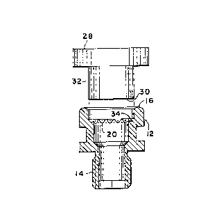
Referring to FIGS. 5 and 6, a second punch, denoted by reference numeral
28, is provided and is shown having a generally square or flat bottom 30, with
a diameter 32 sized to have the same diameter as diameter 25 of the punch 22.
Referring to FIG. 6, punch 28 is driven axially into the fitting 12 until the
flafi bottom 30 thereof contacts ring 26 and deforms the ring further in an
axial
direction over the periphery of the screen 20 until the ring 26 has a flat
configuration, as denoted by reference numeral 34; and, the punch is then
removed, Leaving the screen installation completed.
It will be understood that the technique described above with respect to
FIGS. 1 through 6 provides for complete metal encapsulation of the outer
periphery of the screen 20 in a manner which provides for improved and greater
strength retention of the screen in the fitting to resist tampering and
removal
thereof. The construction shown and described provides for a simpler and

~~.~:3_~~~
q. ~3-CON-002 (APJ
lower cost construction of a filter screen for a conduit or port, as compared
with the cup-shaped screens utilized heretofore.
It will be understood that the invention, although described hereinabove
with respect to the illustrated embodiments, is capable of modification and
variation, and is limited only by the following claims.

Representative Drawing
A single figure which represents the drawing illustrating the invention.
Administrative Status

2024-08-01:As part of the Next Generation Patents (NGP) transition, the Canadian Patents Database (CPD) now contains a more detailed Event History, which replicates the Event Log of our new back-office solution.

Please note that "Inactive:" events refers to events no longer in use in our new back-office solution.

For a clearer understanding of the status of the application/patent presented on this page, the site Disclaimer , as well as the definitions for Patent , Event History , Maintenance Fee  and Payment History  should be consulted.

Event History

Description Date
Inactive: IPC from MCD 2006-03-11
Time Limit for Reversal Expired 2005-04-18
Letter Sent 2004-04-19
Grant by Issuance 2000-03-21
Inactive: Cover page published 2000-03-20
Inactive: Final fee received 1999-12-16
Pre-grant 1999-12-16
Letter Sent 1999-07-08
Notice of Allowance is Issued 1999-07-08
Inactive: Approved for allowance (AFA) 1999-06-23
Inactive: Status info is complete as of Log entry date 1998-07-08
Inactive: Application prosecuted on TS as of Log entry date 1998-07-08
Request for Examination Requirements Determined Compliant 1996-02-07
All Requirements for Examination Determined Compliant 1996-02-07
Application Published (Open to Public Inspection) 1994-10-20

Abandonment History

There is no abandonment history.

Maintenance Fee

The last payment was received on 1999-03-18

Note : If the full payment has not been received on or before the date indicated, a further fee may be required which may be one of the following

  • the reinstatement fee;
  • the late payment fee; or
  • additional fee to reverse deemed expiry.

Please refer to the CIPO Patent Fees web page to see all current fee amounts.

Fee History

Fee Type Anniversary Year Due Date Paid Date
Request for examination - standard 1996-02-07
MF (application, 4th anniv.) - standard 04 1998-04-20 1998-03-27
MF (application, 5th anniv.) - standard 05 1999-04-19 1999-03-18
Final fee - standard 1999-12-16
MF (patent, 6th anniv.) - standard 2000-04-18 2000-03-17
MF (patent, 7th anniv.) - standard 2001-04-18 2001-03-21
MF (patent, 8th anniv.) - standard 2002-04-18 2002-03-19
MF (patent, 9th anniv.) - standard 2003-04-18 2003-03-19
Owners on Record

Note: Records showing the ownership history in alphabetical order.

Current Owners on Record
EATON CORPORATION
Past Owners on Record
THOMAS E. DESALVO
Past Owners that do not appear in the "Owners on Record" listing will appear in other documentation within the application.
Documents

To view selected files, please enter reCAPTCHA code :


To view images, click a link in the Document Description column. To download the documents, select one or more checkboxes in the first column and then click the "Download Selected in PDF format (Zip Archive)" or the "Download Selected as Single PDF" button.

List of published and non-published patent-specific documents on the CPD .

If you have any difficulty accessing content, you can call the Client Service Centre at 1-866-997-1936 or send them an e-mail at CIPO Client Service Centre.


Document
Description 
Date
(yyyy-mm-dd) 
Number of pages   Size of Image (KB) 
Cover Page 2000-02-17 1 27
Cover Page 1995-06-24 1 72
Description 1995-06-24 4 331
Claims 1995-06-24 2 129
Abstract 1995-06-24 1 43
Drawings 1995-06-24 1 68
Representative drawing 1998-07-23 1 7
Representative drawing 2000-02-17 1 7
Commissioner's Notice - Application Found Allowable 1999-07-08 1 165
Maintenance Fee Notice 2004-06-14 1 173
Correspondence 1999-12-16 1 27
Fees 1997-03-26 1 61
Fees 1996-03-28 1 78