Language selection

Search

Patent 2121730 Summary

Third-party information liability

Some of the information on this Web page has been provided by external sources. The Government of Canada is not responsible for the accuracy, reliability or currency of the information supplied by external sources. Users wishing to rely upon this information should consult directly with the source of the information. Content provided by external sources is not subject to official languages, privacy and accessibility requirements.

Claims and Abstract availability

Any discrepancies in the text and image of the Claims and Abstract are due to differing posting times. Text of the Claims and Abstract are posted:

  • At the time the application is open to public inspection;
  • At the time of issue of the patent (grant).
(12) Patent Application: (11) CA 2121730
(54) English Title: RAIL LOADING TRAIN FOR TRANSPORTING AND FOR LOADING AND UNLOADING LONG RAILS
(54) French Title: TRAIN SERVANT AU CHARGEMENT, AU TRANSPORT ET AU DECHARGEMENT DE RAILS DE GRANDES DIMENSIONS
Status: Deemed Abandoned and Beyond the Period of Reinstatement - Pending Response to Notice of Disregarded Communication
Bibliographic Data
(51) International Patent Classification (IPC):
  • B61D 3/16 (2006.01)
  • E01B 29/17 (2006.01)
(72) Inventors :
  • HERTELENDI, JOSEF (Germany)
  • STROBL, BRUNO (Germany)
(73) Owners :
  • GEORG ROBEL GMBH & CO.
(71) Applicants :
  • GEORG ROBEL GMBH & CO. (Germany)
(74) Agent: RICHES, MCKENZIE & HERBERT LLP
(74) Associate agent:
(45) Issued:
(22) Filed Date: 1994-04-20
(41) Open to Public Inspection: 1994-10-22
Examination requested: 2000-05-10
Availability of licence: N/A
Dedicated to the Public: N/A
(25) Language of filing: English

Patent Cooperation Treaty (PCT): No

(30) Application Priority Data:
Application No. Country/Territory Date
P 43 12 964.1 (Germany) 1993-04-21

Abstracts

English Abstract


ABSTRACT
A rail loading train for transporting and for loading and
unloading long rails (5) is provided with wagon frames
supported on on-track undercarriages and rail supports (6),
extending at right angles to the longitudinal direction of the
wagon, with rollers provided for supporting the long
rails. These are designed as a flanged roller (9) with a
flange (14) arranged on the end face.
(Fig. 2)


Claims

Note: Claims are shown in the official language in which they were submitted.

Claims
1. A rail loading train for transporting and for loading and
unloading long rails (5), comprising wagon frames (3)
supported on on-track undercarriages (2) and rail supports
(6), extending at right angles to the longitudinal direction
of the wagon, with rollers provided for supporting the long
rails (5) and, if appropriate, vertically extending
spacer bars (13) located between them, characterized in that
each roller is designed as a flanged roller (9) having at
least one flange (14) arranged on the end face.
2. A rail loading train according to claim 1, characterized
in that in order to support a long rail (5) there are
arranged two flanged rollers (9), positioned one behind the
other in the transverse direction of the wagon or rails and
spaced apart from one another, in each case forming a roller
pair (15), the flange (14) being provided in each case on the
opposite end to the mutually adjacent ends (16).
3. A rail loading train according to claim 2, characterized
in that a roller bearing shaft (8) bearing the flanged rollers
(9) arranged one behind the other in the transverse direction
of the wagon is supported by a plurality of shaft bearings
(12), each positioned between the flanged rollers (9) of a
roller pair (15).
4. A rail loading train according to one of claims 1, 2 or
3, characterized in that the width of the spacer bar (13),
extending in the transverse direction of the wagon, is
designed to correspond approximately to the width of two
flanges (14) located beneath the spacer bar (13).
5. A rail loading train according to one of claims 1 to 4,
characterized in that the difference between the diameter of
the flanged roller (9) and that of the flange (14) is designed

to correspond to the height of a rail base, i.e. about 10 to
15 mm.
6. A rail loading train according to one of claims 1 to 5,
characterized in that provided on each roller bearing shaft
(8) of the rail support (6) are a total of twenty flanged
rollers (9), arranged one behind the other, for supporting a
total of ten long rails (5).
7. A rail loading train according to one of claims 1 to 6,
characterized in that the spacer bar (13) is in each case
arranged above two adjacent flanges (14) of two flanged
rollers (9).

Description

Note: Descriptions are shown in the official language in which they were submitted.


2~2~7~
A 93/90001
DE P 43 12 964.1
21 . 04 . 1993
ORIGINAL TEXT
Ma/sp
The invention relates to a rail loading train for
transporting and for loading and unloading long rails,
compri~ing wagon frames supported on on-track undercarria~es
and rail supports, extending at right angles to the
longitudinal direction of the wagon, with rollers provided for
supporting the long rails and, if appropriate,
vertically extending spacer bars located between them.
A rail loading train of this kind is already known from
DE 12 08 326 B and DE 27 34 748 B, comprising a plurality of -
wagons coupled together. Rail supports, attached to the wagon
frame and spaced apart from one another in the longitudinal
direction of the wagon or train, with rollers arranged one
behind the other in the transverse direction of the wagon are
known for supporting the long rails which are to be
transported. The rollers provided for supporting each rail
are 6eparated from one ianother by spacer bars which serve to
separate the rails lying side by side in the transverse
direction of the wagon. Supporting the long rails in
thi~ way has the disadvantage, however, that as a result of
friction of the rail base flank against the adjoining spacer
bar, very considerable tractive forces are required for
loading and unloading.
,
The object of the present invention is now to create a
rail lbading train of the type described in the introduction,
on which the said friction of the long rails to be
transported is reduced.
-. , .
This object i8 achieved according to the invention with a
rail loading train of the type previously defined in that each

2 ~ 2 1 7 .3 0
roller is designed as a flanged roller having at least one
flange arranged on the end face.
With this design of the rollers which support the long
rails, with a minimum of constructional effort the
frictional forces in the region of the rail base flank are
virtually negligible. This is of particular advantage,
particularly for the transport of very long rails, 309 m in
length for example, since as a consequence of the features
according to the invention, even such heavy and long rails can
be moved with a travelling crane, proven in use, without the
crane having to be strengthened, thereby exceeding the
permissible axle load. Also, rail loading trains already in
service can be retrofitted very simply with the constructional
features according to the invention.
A further development according to the features of claims
2, 3 and 4 has the particular advantage that even with the
roller bearing shaft safely supported by a plurality of shaft
bearings, a maximum number of roller pair~ can be arranged in
the transverse direction of the wagon. The long rail
to be transported can be precisely centred before being laid
on the roller pair by means of the spacer bar situated above
the two flanges, with the result that the rail base comes to
lie between the two flanges of a roller pair without any
problem.
Another further development is that the difference
between the diameter of the flanged roller and that of the
flange is designed to correspond to the height o$ a rail base,
i.e. about 10 to 15 mm. In this case adequate transverse
guiding of the long rail is ensured even in track
bends .
The invention is described in more detail in the
following with the aid of embodiments shown in the drawing, in
which
. ~.:............ . . ~ , . -.
:~, . : .
: ; -- ~ . :
:~ :
:: :: : , : ~, ,: " ~ ~
. , ~ ~ . . . : .
: .: : :

2~217~0
Fig. 1 shows a partial side view of a rail loading train
comprising rail supports provided for supporting long
rails and having a plurality of flanged rollers,
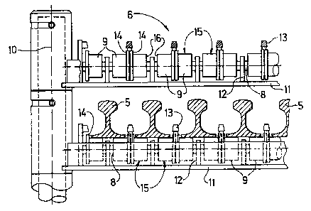
Fig. 2 shows a greatly enlarged detailed view of a rail
support,
Fig. 3 shows a plan view of a part of the said rail
support, and
Fig. 4 shows another variant of a flainged roller for
supporting long rails.
The rail loading train 1 shown in Fig. 1 is composed of
several loading wagons 4 coupled together and having on-track
undercarriages 2 and wagon frames 3. Long rails 5
situated on the rail loading train 1 are supported on a -~
plurality of rail supports 6 arranged at specific distances
from one another in the longitudinal direction of the wagon
and each connected to the wagon frame 3. Many of the rail
supports 6 are shown in an inoperative position extending in
the longitudinal direction of the wagon. 7 denotes a jib arm
of a gantry crane, designed to travel on the wagon frames 3 in
the longitudinal direction of the train, for transferring ~ ~;
tractive or thrust forces to the long rails 5 which are
to be moved.
As shown in Fig. 2 and 3, each rail ~upport 6 is provided
with roller bearing shafts 8 arranged one above another and
extending in operative use at right angles to the longitudinal
direction of the wagon and horizontally. Arranged one behind
the other and mounted thereon are a plurality of rollers, each
designed as a flanged roller 9. In order to support each
roller bearing shaft 8, each of which i~ mounted at one end `
for pivot~ng about a vertical axis 10 in the longitudinal
direction of the wagon, there are provided shaft bearin~s 12
which are spaced apart from one another in the tran~verse

2~217~0
direction of the wagon and which are connected to a base
support 11 extending parallel to the shaft 8. Provided
centrally in each case between the roller bearings 12, with
respact to the longitudinal direction of the 6haft, ix a
r-pacer bar 13 which is connected to the base support 11. Each
flanged roller 9 has a flange 14 in the region of the spacer
bar 13. Positioned between two spacer bars 13 are two flanged
rollers 9, in each case forming a roller pair 15, for jointly
supporting a long rail 5, the flanges 14 in each case
being provided on the opposite end to the mutually adjacent
ends 16. :
The width of a spacer bar 13, extending in the transverse
direction of the wagon, corresponds to the width of two
flange~ located beneath the spacer bar 13. The difference
between the diameter of the each cylindrical portion of the
flanged roller 9, which serves to support the long rail
5, and the diameter of the flange 14 is preferably in the :
region of about 10 to about 15 mm. Provided on each roller
bearing shaft 8 of the rail support 6 are a total of 20
flanged rollers 9 for supporting a total of 10 long :;
rails 5.
The variant of a flanged roller 9 shown in Fig. 4 has
instead of a spacer bar a sub~tantially enlarged flange 14, so
that thi~ takes over both the centreing function of the spacer
bar discussed above and the lateral guiding of the long
rail 5.
- ~

Representative Drawing
A single figure which represents the drawing illustrating the invention.
Administrative Status

2024-08-01:As part of the Next Generation Patents (NGP) transition, the Canadian Patents Database (CPD) now contains a more detailed Event History, which replicates the Event Log of our new back-office solution.

Please note that "Inactive:" events refers to events no longer in use in our new back-office solution.

For a clearer understanding of the status of the application/patent presented on this page, the site Disclaimer , as well as the definitions for Patent , Event History , Maintenance Fee  and Payment History  should be consulted.

Event History

Description Date
Inactive: IPC from MCD 2006-03-11
Application Not Reinstated by Deadline 2004-12-10
Inactive: Dead - Final fee not paid 2004-12-10
Deemed Abandoned - Failure to Respond to Maintenance Fee Notice 2004-04-20
Deemed Abandoned - Conditions for Grant Determined Not Compliant 2003-12-10
Notice of Allowance is Issued 2003-06-10
Letter Sent 2003-06-10
Notice of Allowance is Issued 2003-06-10
Inactive: Approved for allowance (AFA) 2003-06-02
Amendment Received - Voluntary Amendment 2003-02-04
Inactive: S.30(2) Rules - Examiner requisition 2002-08-29
Amendment Received - Voluntary Amendment 2002-07-08
Inactive: S.30(2) Rules - Examiner requisition 2002-02-06
Inactive: Application prosecuted on TS as of Log entry date 2000-06-01
Letter Sent 2000-06-01
Inactive: Status info is complete as of Log entry date 2000-06-01
All Requirements for Examination Determined Compliant 2000-05-10
Request for Examination Requirements Determined Compliant 2000-05-10
Application Published (Open to Public Inspection) 1994-10-22

Abandonment History

Abandonment Date Reason Reinstatement Date
2004-04-20
2003-12-10

Maintenance Fee

The last payment was received on 2003-02-05

Note : If the full payment has not been received on or before the date indicated, a further fee may be required which may be one of the following

  • the reinstatement fee;
  • the late payment fee; or
  • additional fee to reverse deemed expiry.

Please refer to the CIPO Patent Fees web page to see all current fee amounts.

Fee History

Fee Type Anniversary Year Due Date Paid Date
MF (application, 4th anniv.) - standard 04 1998-04-20 1998-03-06
MF (application, 5th anniv.) - standard 05 1999-04-20 1999-03-05
MF (application, 6th anniv.) - standard 06 2000-04-20 2000-03-06
Request for examination - standard 2000-05-10
MF (application, 7th anniv.) - standard 07 2001-04-20 2001-02-08
MF (application, 8th anniv.) - standard 08 2002-04-22 2002-02-06
MF (application, 9th anniv.) - standard 09 2003-04-21 2003-02-05
Owners on Record

Note: Records showing the ownership history in alphabetical order.

Current Owners on Record
GEORG ROBEL GMBH & CO.
Past Owners on Record
BRUNO STROBL
JOSEF HERTELENDI
Past Owners that do not appear in the "Owners on Record" listing will appear in other documentation within the application.
Documents

To view selected files, please enter reCAPTCHA code :


To view images, click a link in the Document Description column. To download the documents, select one or more checkboxes in the first column and then click the "Download Selected in PDF format (Zip Archive)" or the "Download Selected as Single PDF" button.

List of published and non-published patent-specific documents on the CPD .

If you have any difficulty accessing content, you can call the Client Service Centre at 1-866-997-1936 or send them an e-mail at CIPO Client Service Centre.


Document
Description 
Date
(yyyy-mm-dd) 
Number of pages   Size of Image (KB) 
Representative drawing 1998-08-25 1 13
Claims 2003-02-04 2 56
Representative drawing 2003-06-02 1 16
Abstract 1995-04-08 1 10
Drawings 1995-04-08 1 28
Description 1995-04-08 4 139
Claims 2002-07-08 2 60
Cover Page 1995-04-08 1 67
Claims 1995-04-08 2 93
Acknowledgement of Request for Examination 2000-06-01 1 177
Commissioner's Notice - Application Found Allowable 2003-06-10 1 160
Courtesy - Abandonment Letter (NOA) 2004-02-18 1 168
Courtesy - Abandonment Letter (Maintenance Fee) 2004-06-15 1 175
Fees 2003-02-05 1 35
Fees 2000-03-06 1 37
Fees 2002-02-06 1 35
Fees 1999-03-05 1 39
Fees 1998-03-06 1 45
Fees 2001-02-08 1 36
Fees 1996-03-05 1 41
Fees 1997-03-05 1 37