Language selection

Search

Patent 2122375 Summary

Third-party information liability

Some of the information on this Web page has been provided by external sources. The Government of Canada is not responsible for the accuracy, reliability or currency of the information supplied by external sources. Users wishing to rely upon this information should consult directly with the source of the information. Content provided by external sources is not subject to official languages, privacy and accessibility requirements.

Claims and Abstract availability

Any discrepancies in the text and image of the Claims and Abstract are due to differing posting times. Text of the Claims and Abstract are posted:

  • At the time the application is open to public inspection;
  • At the time of issue of the patent (grant).
(12) Patent: (11) CA 2122375
(54) English Title: LUMINESCENCE MEASURING SYSTEM AND LUMINOMETER DEVICE
(54) French Title: SYSTEME DE MESURE DE LUMINESCENCE ET LUMINOMETRES
Status: Expired and beyond the Period of Reversal
Bibliographic Data
(51) International Patent Classification (IPC):
  • G01N 21/13 (2006.01)
  • G01N 21/76 (2006.01)
(72) Inventors :
  • WIHLBORG, NILS (Sweden)
(73) Owners :
  • PERSTORP ANALYTICAL AB
(71) Applicants :
  • PERSTORP ANALYTICAL AB (Sweden)
(74) Agent: GOWLING WLG (CANADA) LLP
(74) Associate agent:
(45) Issued: 1997-12-16
(86) PCT Filing Date: 1992-10-29
(87) Open to Public Inspection: 1993-05-13
Examination requested: 1994-06-14
Availability of licence: N/A
Dedicated to the Public: N/A
(25) Language of filing: English

Patent Cooperation Treaty (PCT): Yes
(86) PCT Filing Number: PCT/SE1992/000749
(87) International Publication Number: WO 1993009420
(85) National Entry: 1994-04-27

(30) Application Priority Data:
Application No. Country/Territory Date
9103150-0 (Sweden) 1991-10-29

Abstracts

English Abstract


A luminescence measuring system comprises means (26) for supplying samples located in separate test tubes (25). In the
measuring chamber of a luminometer, the samples are in turn presented to a light detector, such as a photomultiplier. Two
mutually displaceable components (1, 2), which are cup-shaped and fit into one another with the cup bottoms facing outwards, define
the measuring chamber (5). The component shells are provided with holes (11, 12, 11', 12', 14, 15, 16, 17) which can be aligned by
displacement of the components so as to admit the test tube into the luminometer and the measuring chamber (5) and to
discharge it therefrom under the action of gravity. The test tubes are conveyed to the luminometer by a sleeve-chain conveyor having
a bottom with a through hole.


French Abstract

Un système de mesure de la luminescence comprend des moyens (26) pour la fourniture d'échantillons placés dans des éprouvettes séparées (25). Dans la chambre à mesurer d'un luminomètre, les échantillons sont tour à tour présentés à un détecteur de lumière, comme un photomultiplicateur. Deux composants mutuellement déplaçables (1, 2) en forme de coupelles qui se logent l'un dans l'autre et dont les coupelles font face à l'extérieur, délimitent la chambre à mesurer (5). Les enveloppes des composants ont des trous (11, 12, 11', 12', 14, 15, 16, 17) qui peuvent être alignés en déplaçant les composants de façon à introduire l'éprouvette dans le luminomètre et la chambre à mesurer (5) et à la décharger par gravité. Les éprouvettes sont acheminées au luminomètre par un convoyeur à chaîne à manchons ayant un fond muni d'un trou de passage.

Claims

Note: Claims are shown in the official language in which they were submitted.

CLAIMS
1. A luminescence measuring system comprising
a conveyor (26) for containers (25) with samples to
be subjected to luminescence measurements, and
a luminometer (1, 2) arranged to receive the
containers one after the other from the conveyor and
comprising two mutually displaceable components (1, 2) having
holes (11, 12, 14, 15) for admitting, under the action of
gravity, a container into a measuring chamber (5) defined
by said components, as well as holes for removing the
container from the measuring chamber,
c h a r a c t e r i s e d in that
the conveyor comprises a translationally drivable
chain of tubular sleeves (27), each adapted to receive
a container, and a bottom (28) provided with a hole (29),
said chain of sleeves being adapted to be displaced on
the bottom above the hole (29) for dropping a container
through said hole under the action of gravity, and
the luminometer is arranged below said bottom and the
mutually displaceable components thereof (1, 2) are
cup-shaped, fitting into one another with the cup bottoms
facing outwards, the shells of said components exhibiting
said admission holes as well as other holes (11', 12', 16,
17) which can be brought into alignment by said displacement
for discharging the container from the measuring
chamber and the luminometer under the action of gravity.
2. A luminescence measuring system as set forth in
claim 1, c h a r a c t e r i s e d in that said components
(1, 2) are mutually displaceable by rotation.
3. A luminescence measuring system as set forth in
claim 1 or 2, c h a r a c t e r i s e d in that the two
cup-shaped components (1, 2) both have a double shell.
4. A luminescence measuring system as set forth in
any one of claims 1-3, c h a r a c t e r i s e d in that
the inner shell (9) of the one cup-shaped component is

covered by a top (10) and defines the measuring chamber
(5).
5. A luminescence measuring system as set forth in
any one of claims 1-4, c h a r a c t e r i s e d in
that said top (10) is provided with a guide (23) for a
spring-loaded cam (20) projecting from the bottom of the
other component and adapted to sense, respectively, the
presence and the absence of a test tube in the measuring
chamber (5).
6. A luminometer device, comprising
a conveyor (26) for containers (25) with samples to
be subjected to luminescence measurements, and
a luminometer (1, 2) arranged to receive the
containers one after the other from the conveyor and
comprising two mutually displaceable components (1, 2) having
holes (11, 12, 14, 15) for admitting, under the action of
gravity, a container into a measuring chamber (5) defined
by said components, as well as holes for removing the
container from the measuring chamber,
c h a r a c t e r i s e d in that
the conveyor comprises a translationally drivable
chain of tubular sleeves (27), each adapted to receive
a container, and a bottom (28) provided with a hole (29),
said chain of sleeves being adapted to be displaced on
the bottom above the hole (29) for dropping a container
through said hole under the action of gravity, and
the luminometer is arranged below said bottom and
the mutually displaceable components thereof (1, 2) are
cup-shaped, fitting into one another with the cup bottoms
facing outwards, the shells of said components exhibiting
said admission holes as well as other holes (11', 12',
16, 17) which can be brought into alignment by said
displacement for discharging the container from the
measuring chamber and the luminometer under the action of
gravity.

7. A luminometer device as set forth in claim 6,
c h a r a c t e r i s e d in that said components (1, 2)
are mutually displaceable by rotation.
8. A luminometer device as set forth in claim 6 or 7,
c h a r a c t e r i s e d in that the two cup-shaped
components (1, 2) both have a double shell.
9. A luminometer device as set forth in any one of
claims 6-8, c h a r a c t e r i s e d in that the inner
shell (9) of the one cup-shaped component is covered by a
top (10) and defines the measuring chamber (5).
10. A luminometer device as set forth in any one of
claims 6-9, c h a r a c t e r i s e d in that said top
(10) is provided with a guide (23) for a spring-loaded
cam (20) projecting from the bottom of the other component
and adapted to sense, respectively, the presence and the
absence of a test tube in the measuring chamber (5).

Description

Note: Descriptions are shown in the official language in which they were submitted.


W093/09420 PCT/SE92/00749
212237~
LUMINESCENCE MEASURING SY~lhM AND LUMINOMETER DEVICE
The present invention relates to a luminescence mea-
suring ~ em and a luminometer device, i.e. a device
which ls designed for making b~olumi n~Scence and chemi-
lumln~oe..~e measurements and in which test tubes with the
suL~ ,e~ to be analysed by luminescence are conveyed, in
a series of test-tube holders, past a measuring station
hav~ng a light detector, such as a photomultiplier.
EP-A-0'226 374 and US-A-4,863,690, for instance, dis-
close lumine-.c~-lc~- measuring systems. The former publica-
-tion describes a complex rotary device for removing the
test tubes from the holders one after the other and intro-
d~c~ng them into a measuring chamber, which itself is of
complex design. The latter publication describes a measur-
ing system having special holders for the test tubes.
The ob~ects of the invention are to provide a lumine-
~ce..c,e measuring system and a luminometer device which is
-- simple, does not require any special holders for the test
tubes, and is reliably lightproof during the measurements.
According to the invention, these objects are achiev-
ed by a luminescence measuring system and a luminometer
device as defined in the appended claims.
The invention will be described in more detail below
with reference to the accompanying drawings, in which
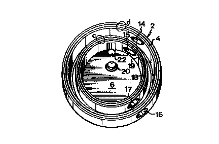
Fig. 1 is a perspective view of the inside of a mov-
able component of the device;
Fig. 2 is a perspective view of the outside of a
fixed component;
Fig, 3 is a perspective view of the outside of the
movable component;
Fig. 4 is a perspective view of the inside of the
fixed component;
Fig. 5 is a sectional view of the fixed component
taken along the line V-V in Fig. 4; and
.

W093/09420 212 2 3 7 5 PCT/SE92/007~9
Fig. 6 schematically illustrates the operation of the
inventive device in association with a chain conveyor for
test tubes, forming a lum~ne~cence measuring system.
The luminometer comprlses a cup-shaped component 1
which is fixedly mounted on a frame, and a cup-shaped com-
- ponent 2 which is rotatable o~nd the fixed component 1
about a common axis and which forms a lid for the fixed
component 1 when an annular flange or shell wall 3 of the
fixed component has been fitted into an ~nular groove 4
in the'movable component 2. The An~ r flange 3 encloses
a measuring chamber 5 in the fixed comronent 1. This cham-
ber can be accommodated in a space 6 in the movable compo-
nent 2. The measuring chamb~r 5 is fitted in the space 6
with sliding fit, as is the flange 3 in the annular sroove
4. The components are made in one piece.
At the outside, the component 1 has a threaded hole 7
in which the head of a photomultiplier (not shown) can be
s~ ed. The ~o~om of the hole 7 defines a smaller cir-
cular hole 8 having a diameter ~ust about equal to the
diameter of the test tube (such as 25 in Fig. 6) whose
content is to be analysed by luminescence measurement. The
hole 8 opens in the measuring chamber S, which is defined
by a closed peripheral wall 9 and a top 10~ The flance 3
and the peripheral wall 9 are provided with through holes
11, 12, 11', 12', which all are located on a diameter of
~ the component 1, the diametral line passing through the
- centre of the hole 8, and whose diameter slightly exceeds
that of the test tubes. A dome-shaped recess 13 extends
from the hole 12 to the hole 12' so as to gùide the lower
sample-~n~ining part of a test tube to a position oppo-
site to the hole 8. The distance between the holes l_ and
12' equals the length of the test tube.
The component 1 is also provided with holes 14, 15,
16, 17 in its outer shell wall and in the flange or ~nner
shell w811 18 which, together wlth the outer shell wall,
defines the annular g~ve 4 and which defines the space 6
for the measuring chamber 5. The holes 14, 15 are aligned

W093/09420 PCT/SE92/~749
2122375
along a diameter, as are the holes 16, 17. However, the
axes of the pairs of holes 14, 15 and 16, 17 form an angle
of about 70~ with one another.
It will now be appreciated that, when the components
1 and 2 ~ng-ge one another, the holes 14, 15 and 16, 17
can be brought into alignment with the holes 11, 11' and
12, 12', respectively, by rotating the movable component
2, so as to allow test tubes to enter as well as leave the
measuring chamber 5. An intermediate position in which
light is scr~en~ off provides a measuring position. It is
also unde ~oo~ that'the test'tube can only be admitted or
~harged under the action of grav~ty, if, as int~nAe~,
the holes 11, 12, 11', 12' of the fixed component 1 con-
tain the vertical.
Fnh-~ce~ lightproofness in lum~ne~oe-,~e measurements
can be achieved by ribs and contersunk portions on/in
mating parts of the comp~n~nts 1 and 2 (see the encircled
parts a, b, c, d)'.
After admission, the test tube will rest in the mea-'
2~ suring chamber 5 with its lower sample-containing part
located opposite to the hole 8 by abutting against the
inner surface 19 of the flange 18.
A spring-loaded cam 20 is arranged in the movable
compnnent 2 to follow a groove 21 in the top 10. The cam
20 is adapted to turn on an electric switch 21' when it
is moved apart, against the spring load, by a test tube
in the measuring chamb'er during the rotation of the mov-
able component 2. The switch 21' is adapted to actuate a
pump for supplying a reagent to the test tube. The rea-
gent i~ supplied through a bent in~ection needle and a
hose (not shown). The in;ection needle is introduced from
outside in a lightproof manner through a hole 22 in the
~ component 2 and follows the movement thereof in a recess
23 in the peripheral wall 9 of the'measuring chamber.
The movable component 2 is rotated by an electric
step motor (not shown), whose shaft engages dead holes 24
in the outside of the movable component and which rotates

W093/ ~ 20 21 2 2 3 7 ~ PCT/SE92/~749
the movable component 2 between the measuring positionand, alternatingly, the admission and discharge positions.
The test tubes 25 are con~eyed in a chain after one
another along a path (Fig. 6) comprising a motor-driven
S con~o~ 26 with ch~in links consisting of sleeves 26,
each con~A~n~n~ test tubes with material to be analysed in
the measuring chamber by luminc-~ence.
The tes~ tubes 25 are f~tted in the sleeves 27 with
~ n~ fit. When con~ey~ towards the luminometer, the
t~st tubes are ~pported by their base portlons on a sup-
port structure or bottom 28 hav~ng a hole 29 which is
}ocated opposite to the holes 11, 12, 11', 12' of the fix-
ed component 1, and adapted to let through the test tubes.
The measuring plu~u~e ~s contro}led by a computer
in-the following manner.
When a sleeve 27 with a test tube 25 re~he-c, along
its conveying path, the hole 29 straight above the site of
the-luminometer, the rotatable component 2 is set in the
measuring position described above. The computer stops the
co--~yor 26, and the test tube 25 ~osc~nA~ into the hole
29 so as to abut against the outer shell of the component
2. Normally, i.e. when the pr~c~in~ test tube has been
discharged from the measuring chamber, the motor then
receives a signal from the computer to rotate the movable
component 2 in a direction to bring the holes 11, 12 (11',
~ 12'~ and the holes 14, 15 into vertical alignment straight
below the hole 29, and the test tube 25 drops into the
measuring chamber 5.
The computer then transmits a signal to the motor to
rotate the,movable component to the lumine-s~nce-sensing
measuring position, in which the presence of the test tube
is-sensed by the elements 20, 21 so as to activate the
reagent pump which injects the reagent into the test tube
through the injection ne~dle. The dwell time, determined
by the computer, of the sample in the measuring chamber is
about 10 s in the case of biolumjne~ence measurement with
LUMIT for determination of ATP. Then, the computer si~-

W093/09420 PCT/SE92/00749
2122375
5nals to the motor to rotate the movable component in a
direction to bring the holes 11', 12' (11, 12) into align-
ment wlth the holes 16, 17, whereby the test tube can be
dlscharged, under the action of gravity, from the lumino-
meter to a collection site 29, which may be a waste con-
- tainer or, if the sample is to be further analysed, a
sleeve in another test-tube con~c~ol.
In the event a test tube, for some reason or other,
is left in the measuring chamber 5 in engagement with the
cam 20 in the measuring chamber 5 when a new sample is to
be analysed, the computer is adapted to actuate the motor
to once again rotate the movable component to the
discharging position, without any prece~i~g actuation of
. the reagent pump. Further, if no new test tube is admitted
into the measuring chamber 5 after a pr~c~ing discharge,
the oomputer is adapted to actuate the motor to rotate the
~ movable component once.again to the admitting position
- without any p~c~ng injection of reagent.
It is unde~s~ovd that the inventive idea of.admitting
and ~lscharging samples under the action of gravity can be
implemented also in other ways. Thus, the admitting and
discharging positions are not necessarily reached by rota-
tion. Alternatively, use is made of square components 1
and 2, in which case the component 2 is displaced in a
translational fashion on the fixed component 1.
_

Representative Drawing
A single figure which represents the drawing illustrating the invention.
Administrative Status

2024-08-01:As part of the Next Generation Patents (NGP) transition, the Canadian Patents Database (CPD) now contains a more detailed Event History, which replicates the Event Log of our new back-office solution.

Please note that "Inactive:" events refers to events no longer in use in our new back-office solution.

For a clearer understanding of the status of the application/patent presented on this page, the site Disclaimer , as well as the definitions for Patent , Event History , Maintenance Fee  and Payment History  should be consulted.

Event History

Description Date
Inactive: IPC from MCD 2006-03-11
Time Limit for Reversal Expired 2002-10-29
Letter Sent 2001-10-29
Grant by Issuance 1997-12-16
Inactive: Application prosecuted on TS as of Log entry date 1997-10-14
Inactive: Status info is complete as of Log entry date 1997-10-14
Pre-grant 1997-08-19
Notice of Allowance is Issued 1997-04-22
All Requirements for Examination Determined Compliant 1994-06-14
Request for Examination Requirements Determined Compliant 1994-06-14
Application Published (Open to Public Inspection) 1993-05-13

Abandonment History

There is no abandonment history.

Maintenance Fee

The last payment was received on 1997-09-16

Note : If the full payment has not been received on or before the date indicated, a further fee may be required which may be one of the following

  • the reinstatement fee;
  • the late payment fee; or
  • additional fee to reverse deemed expiry.

Please refer to the CIPO Patent Fees web page to see all current fee amounts.

Fee History

Fee Type Anniversary Year Due Date Paid Date
Final fee - standard 1997-08-19
MF (application, 5th anniv.) - standard 05 1997-10-29 1997-09-16
MF (patent, 6th anniv.) - standard 1998-10-29 1998-09-18
MF (patent, 7th anniv.) - standard 1999-10-29 1999-09-16
MF (patent, 8th anniv.) - standard 2000-10-30 2000-09-19
Owners on Record

Note: Records showing the ownership history in alphabetical order.

Current Owners on Record
PERSTORP ANALYTICAL AB
Past Owners on Record
NILS WIHLBORG
Past Owners that do not appear in the "Owners on Record" listing will appear in other documentation within the application.
Documents

To view selected files, please enter reCAPTCHA code :


To view images, click a link in the Document Description column. To download the documents, select one or more checkboxes in the first column and then click the "Download Selected in PDF format (Zip Archive)" or the "Download Selected as Single PDF" button.

List of published and non-published patent-specific documents on the CPD .

If you have any difficulty accessing content, you can call the Client Service Centre at 1-866-997-1936 or send them an e-mail at CIPO Client Service Centre.


Document
Description 
Date
(yyyy-mm-dd) 
Number of pages   Size of Image (KB) 
Cover Page 1997-12-11 1 58
Cover Page 1995-08-19 1 44
Abstract 1995-08-19 1 69
Claims 1995-08-19 3 132
Drawings 1995-08-19 4 100
Description 1995-08-19 5 267
Representative drawing 1997-12-11 1 15
Maintenance Fee Notice 2001-11-26 1 178
Fees 1996-10-08 1 41
Fees 1994-10-13 1 46
Fees 1995-10-10 1 40
National entry request 1994-04-27 4 144
Prosecution correspondence 1994-04-27 3 144
International preliminary examination report 1994-04-27 8 263
Prosecution correspondence 1994-06-14 1 28
PCT Correspondence 1994-10-31 1 50
Correspondence related to formalities 1997-08-19 1 29