Language selection

Search

Patent 2122521 Summary

Third-party information liability

Some of the information on this Web page has been provided by external sources. The Government of Canada is not responsible for the accuracy, reliability or currency of the information supplied by external sources. Users wishing to rely upon this information should consult directly with the source of the information. Content provided by external sources is not subject to official languages, privacy and accessibility requirements.

Claims and Abstract availability

Any discrepancies in the text and image of the Claims and Abstract are due to differing posting times. Text of the Claims and Abstract are posted:

  • At the time the application is open to public inspection;
  • At the time of issue of the patent (grant).
(12) Patent: (11) CA 2122521
(54) English Title: MONITORING GASEOUS OXYGEN CONCENTRATION
(54) French Title: CONTROLE PERMANENT DE LA CONCENTRATION EN OXYGENE GAZEUX
Status: Expired and beyond the Period of Reversal
Bibliographic Data
(51) International Patent Classification (IPC):
  • G01N 27/417 (2006.01)
  • G01D 18/00 (2006.01)
  • G01N 33/00 (2006.01)
  • G01N 37/00 (2006.01)
  • G08B 21/00 (2006.01)
(72) Inventors :
  • HART, RUSSELL F. (United States of America)
  • CAO, TUAN Q. (United States of America)
(73) Owners :
  • LITTON SYSTEMS INC.
(71) Applicants :
  • LITTON SYSTEMS INC. (United States of America)
(74) Agent: BERESKIN & PARR LLP/S.E.N.C.R.L.,S.R.L.
(74) Associate agent:
(45) Issued: 1998-10-27
(22) Filed Date: 1994-04-29
(41) Open to Public Inspection: 1994-11-12
Examination requested: 1994-04-29
Availability of licence: N/A
Dedicated to the Public: N/A
(25) Language of filing: English

Patent Cooperation Treaty (PCT): No

(30) Application Priority Data:
Application No. Country/Territory Date
060,275 (United States of America) 1993-05-11

Abstracts

English Abstract


Apparatus for monitoring gaseous oxygen concentration that
includes an oxygen sensor for providing an electrical sensor signal
that varies as a function of oxygen concentration at the sensor.
Processor circuitry compares oxygen concentration indicated by the
sensor signal to at least one threshold level, and indicates when
such oxygen concentration at the sensor departs from such threshold
concentration level. The apparatus is calibrated by exposing the
sensor to a calibration gas having an oxygen concentration equal to
the desired threshold concentration level, and storing in the
processor circuitry electrical indicia indicative of operating
characteristics of the sensor at such threshold oxygen concentration
level. When the apparatus is thereafter employed for monitoring a
gas of undetermined oxygen concentration, the operating
characteristics of the sensor reflected by the sensor output signal
are compared to the prestored indicia for determining when oxygen
concentration at the sensor crosses the threshold concentration level.


French Abstract

Cette invention concerne un appareil de contrôle de la concentration d'oxygène gazeux qui comprend un détecteur d'oxygène qui envoie un signal électrique variant en fonction de la concentration d'oxygène au détecteur. Un circuit de traitement compare la concentration d'oxygène correspondant au signal émis à au moins un niveau de consigne pour déterminer si la concentration détectée diffère de ce niveau. L'étalonnage de l'appareil se fait en exposant le détecteur à un gaz d'étalonnage dont la teneur en oxygène est égale au niveau de consigne voulu et en mémorisant dans le circuit de traitement une valeur électrique représentant les paramètres d'état du détecteur à une concentration d'oxygène correspondant au niveau de consigne susmentionné. Lorsque l'appareil est mis en service pour contrôler une atmosphère dont la teneur en oxygène est inconnue, les paramètres d'état du détecteur indiqués par le signal émis par celui-ci sont comparés à la valeur précédemment entrée dans le circuit de traitement, afin de déterminer si la concentration détectée franchit le niveau de consigne.

Claims

Note: Claims are shown in the official language in which they were submitted.


THE EMBODIMENTS OF THE INVENTION IN WHICH AN EXCLUSIVE
PROPERTY OR PRIVILEGE IS CLAIMED ARE DEFINED AS FOLLOWS:
1. Apparatus for monitoring gaseous oxygen
concentration comprising:
an oxygen sensor for providing an electrical
sensor signal that varies as a function of oxygen
concentration at said sensor,
processor circuit means responsive to said
electrical signal for comparing oxygen concentration
indicated by said signal to at least one threshold level,
means responsive to said processor circuit means
for indicating when oxygen concentration at said sensor
departs from said threshold level, and
means for calibrating said processor circuit
means to said at least one threshold level.
2. The apparatus set forth in claim 1 wherein said
calibrating means comprises means for exposing said sensor
to gas having an oxygen concentration equal to said
threshold level, and means responsive to said electrical
signal from said sensor for automatically storing
calibration indicia indicative of said sensor signal at
said threshold concentration level, said processor circuit
means including means for retrieving said stored indicia
for comparison to said sensor signal to determine when
oxygen concentration indicated by said signal departs from
said threshold level.
3. The apparatus set forth in claim 2 wherein said
means for storing said indicia comprises a non-volatile
memory.
4. The apparatus set forth in claim 3 wherein said
calibrating means comprises means for storing indicia in

said non-volatile memory indicative of said sensor signal
at a plurality of said threshold concentration levels.
5. The apparatus set forth in claim 4 wherein said
processor means includes means responsive to said sensor
signal for comparing oxygen concentration indicated by
said signal to multiple threshold levels, and means
responsive to such comparison for indicating improper
operation of said apparatus.
6. The apparatus set forth in claim 2 wherein said
calibrating means further comprises means removably
connected to said processor circuit for controlling
calibration of said processor circuit while said sensor is
exposed to said gas.
7. The apparatus set forth in claim 6 wherein said
sensor and said processor circuit means are mounted
together on a circuit board assembly, and wherein said
removably connected means comprises a switch socket on
said assembly and a switch removably mounted on said
socket.
8. The apparatus set forth in claim 7 wherein said
processor circuit includes a microprocessor, said switch
socket being connected to I/O ports of said
microprocessor.
9. The apparatus set forth in claim 2 wherein said
sensor and said processor circuit are mounted together on
a circuit board assembly, said assembly including card-edge
contact means along one edge of said assembly for
electrical connection to said processor circuit means.
10. The apparatus set forth in claim 9 wherein said
sensor is disposed adjacent to said one edge, and wherein

said calibrating means comprises means for mating
reception of said card-edge contact means to control
calibrating of said processing means and means for
exposing said sensor to a calibration gas having an oxygen
concentration equal to said threshold level when the
circuit board assembly is inserted in said
mating-reception means.
11. Apparatus for monitoring gaseous oxygen
concentration comprising:
a solid state oxygen sensor for providing an
electrical sensor signal that varies as a function of
oxygen concentration at said sensor,
means for heating said sensor to an elevated
temperature above ambient temperature,
processor circuit means responsive to said
electrical signal for comparing oxygen concentration
indicated by said signal to at least one threshold level,
and
means responsive to said processor circuit means
for indicating when oxygen concentration at said sensor
departs from said threshold level.
12. The apparatus set forth in claim 11 wherein said
sensor provides said electrical current signal as an
analog function of oxygen concentration, and wherein said
apparatus further comprises means for converting said
analog current signal into a periodic signal for said
processor circuit means having time duration and/or
frequency that varies as a function of said analog signal.
13. Apparatus for monitoring gaseous oxygen
concentration comprising:
an oxygen sensor for providing an electrical
sensor signal that varies as a function of oxygen
concentration at said sensor,

processor circuit means responsive to said
electrical signal for comparing oxygen concentration
indicated by said signal to at least one threshold level,
and
LED means responsive to said processor circuit
means for indicating when oxygen concentration at said
sensor departs from said threshold level.
14. Apparatus for monitoring gaseous oxygen
concentration comprising:
an oxygen sensor for providing an electrical
sensor signal that varies as a function of oxygen
concentration at said sensor,
processor circuit means responsive to said
electrical signal for comparing oxygen concentration
indicated by said signal to at least one threshold level,
and
audible alarm means responsive to said processor
circuit means for indicating when oxygen concentration at
aid sensor departs from said threshold level.
15. A method of monitoring oxygen gas concentration
comprising the steps of:
(a) exposing an oxygen sensor to a test gas
containing oxygen at a concentration corresponding to a
preset threshold level,
(b) storing electrical indicia indicative of
operation of said sensor at said threshold level in said
test gas,
(c) exposing said sensor to a gas and providing
an electrical sensor signal as a function of oxygen
concentration in the gas,
(d) comparing oxygen concentration indicated by
said sensor signal to said threshold level by comparing
operation of said sensor to said indicia stored in said
step (b), and

(e) indicating when oxygen concentration departs
from said threshold level.
16. The method set forth in claim 15 comprising the
additional step of:
(f) indicating a possible malfunction of said
sensor when said electrical signal indicates an oxygen
concentration outside of a predetermined range.
17. A method of monitoring oxygen concentration
comprising the steps of:
(a) exposing an oxygen sensor to first and second
test gases containing oxygen at predetermined first and
second concentrations,
(b) electronically storing indicia indicative of
operation of said sensor while exposed to said test gases
at each of said first and second concentrations
respectively in said step (a),
(c) exposing said sensor to gas of undetermined
oxygen concentration while electronically monitoring
operation thereof, and
(d) indicating that oxygen concentration in the
gas of said step (c) reaches either of said predetermined
first and second concentrations when operating
characteristics of said sensor in step (c) corresponds to
either of said first and second indicia stored in step
(b).

Description

Note: Descriptions are shown in the official language in which they were submitted.


2122~21
WHF/RCC/ds
IIO~l.ORING GAS~OUS OXYG~N CONCBNTRATIO~
The pre~ent invention i~ directed to monitoring of ga~eous
oxygen concentration, and more particularly to a method and apparatus
for indicating when oxygen concentration in a monitored gas equal~
or departs from one or more threchold concentration levels.
Ba~ o~ ' and Su~marY of the In~entlon
There are numerou~ application~ ln which it is desirable
to indicate when ga~eous oxygen concentrat~on departs from - i.e.,
becomes either greater than or less than - one or more predetermined
threshold concentration levels. For example, in the home health
care environment, lt is de~irable to monitor the output of an oxygeD
concentrator to determine when the output oxygen level decrea~e~
below a minimum desired limit, such as eighty-five percent oxygen.
In other industrlal and commerc~al applications, it i8 de~irable to
maintain oxygen concentration bet~een pre~et lower and upper limits.
Current dev$ces for ~onitoring oxygen concentration are expen~ive
and sub~ect to tampering at the application ~ite. It i~ therefore
a general ob~ect of the present invention to provide a méthod and
apparatus for monltoring concentration of oxygen in a test gas and
indicating when such concentration departs from one or more
preselected thre~hold levels, which are inexpensive to manufacture
and implement, which functlon reliably over an extended operating
life, and/or which can be selectlvely reprogrammed at the factory or

~122~21
in the field by properly tralned and equlpped personnel whileresl~tinq
tamperlng by unauthorized or untrained personnel.
Apparatus for monitoring ga~eous oxygen concentratlon in
accordance wlth a presently preferred embodiment of the lnvention
comprlse~ an oxygen ~ensor for provldinq an electrlcal sen~or 31gnal
that varie~ as a function of oxygen concentration at the sensor.
Processor circuitry compares oxyqen concentration indicated by the
sensor slgnal to at lea~t one thre~hold level, and lndicate~ when
such oxygen concentration at the sensor departs from such threshold
concentration level. The apparatus is calibrated by expo3ing ~he
sen~or to a callbration gas having an oxygen concentration equal to
the desired threshold concentration level, and ~toring in the
processor circuitry electrical indicia indicative of operating
characterlstlc~ of the sensor at such thre~hold oxygen concentration
level. When the apparatus is thereafter employed for monitoring a
gas of undetermined oxygen concentration, the operating
characteristics o~ the ~encor reflected by the sensor output signal
are compared to the prestored indicia for determining when oxygen
concentrationatthe sensor cro~se~ the threshold concentrationlevel.
In the preferred embodiment of the invention, the processor
circuitry i8 microproce~sor-based and may be programmed to detect a
plurality of oxygen concentration levels by sequentially exposing
the sensor to calibration gas at the variou~ oxygen concentration
levels, and storing electrical indicia indicative of operation of
the sensor at each such calibration level for later comparlson to
the sensor output during use. Such calibration operation preferably
19 performed at the time of manufacture, and the indicla of one or
-2-
... ,, . : , : .
.: . ~: , . . . ~ .
.: :. : ~ ~, - , . . ~ .
.- ~ , : .

2122.521
more calibration level~ i~ stored ln non-volatile memory for
~ubsequent u~e in the field. The apparatu~ circultry and the sensor
are mounted on a circuitboard assembly, with the sensor and card-
edge electrical contacts dl~posed along one edge of the board. The
board may be plugged into calibration apparatus in which the contacts
are connected to calibration control circuitry and the ~ensor i3
exposed to te~t gas at de~ired oxygen concentration through a manifold
in the calibration apparatus. Recalibration in the field is either
not possible, or requires special knowledge and equipment only
possessed by a trained technician.
Brief Descriptioo of the Drawinqs
The invention, together with additional objects, features
and advantages thereof, will be best understood from the following
description, the appended claims and the acc~ ~nying drawings in
which:
FIG. 1 is a functional bloc~ diagram of apparatu~ for
monitoring oxygen concentration in accordance with one precently
preferred : 'o~ t of the invention;
FIG. 2 is a flowchart that illustrates operation of the
processor circuitry in the embodiment of FIG. l;
FIGS. 3A and 3B are timing diagrams that illustra~e output
of the oxygen sensor in the embodiment of FIG. l; and
FIG.4is a perspective diagram that illustrates calibration
of the apparatus of FIG. 1.

2122~21
Detailed De~cription of Preferred E~boai~ents
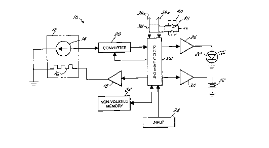
FIG. 1 illustrate~ apparatus 10 for monltoring ga~eou~
oxygen concentration in accordance wlth one presently preferred
embodiment of the invention as compriRing an oxygen concentratlon
sensor 12 having a sensor element 14 of zirconium oxide or other
~ultable solid-Rtate con~truction and a heater element 16 for raiRing
the temperature of sensor element 14 to a ~uitable level above
ambient. Heater 16 i~ energized by an amplifier 18 for raising the
temperature of sensor 12 to a level of 400~C, for example, at which
oxygen ion~ are mobile within the matrix of sen~or element 14. Sen~or
element 14 thuR provide~ an analog electrical current ~ignal that
varie3 a~ a function of oxygen concentration in the ga-~ to which
sensor 12 i8 exposed.
The sensor output signal is fed to a convertor 20, ln which
the analog input signal i~ converted to a format ~uitable for digital
proce~ing. In the preferred embodiment~ of the invention, the
analog input ~ignal is converted to a perlodic 3ignal having
periodicity characteristics - i.e., time duration and/or frequency
- that vary as a function of input current level. Such periodic
signal indicative of oxygen concentration is fed a~ an input to a
processor 22. Processor 22 is connected to a non-vol~tile memory 24
for selectively storing and retrieving calibration and measurement
data. Processor 22 provide~ one output to a driver 26 for energizing
an LED 28, and another output to a driver 30 for activatlng an audible
alarm or buzzer 32. Proce sor 22 may also receive an external control
input 34. Processor 22 also enables operation of convertor when
sen~or output ~ampling 19 required, a~ ~ill be described.
. .
,
. ~ . .
,, . - . . : ~

2122~21
Apparatus 10 lllu~trated ln FIG. 1 18 mo~t preferably
provided in the form of a pr~nted circuitboard assembly 36, as shown
in FIG. 4, havlng sen~or 12 mounted thereon. Processor 22 (FIG. 1 )
has an I/0 bus 38 with lines connected to a series of card-edge
contact~ 38a-38n that extend in an array along one edge of assembly
36 adjacent to sensor 12. ~u~ 38 is also connected wlthin a~sembly 36
to an on-board DIP-~witch socket 40 ~FIG. 1~. Proces~or 22 and non-
volatile memory 24 preferably are provided in the form of a sinqle
integral microprocessor having on-board non-volatile memory for
storing operating software as well a3 sen~or calibration indicia as
will be de-qcribed. Amplifier 18, drivers 26,30 and convertor 20 may
be of any suitable construction. A11 ccmponents of FIG. 1 are on
assembly 36, with the exception of input 35 in ~he preferred
embodiment, which is the calibration unit to be described.
To calibrate apparatu3 10 in accordance with one feature
of the present invention, assembly 36 ~FIG. 4) is plugged into a
calibration fixture 42 that includes both a card-edge connector 4~
for mating with contacts 38a-38n, and a connector 46 for supplying
a calibration gas at predetermined oxygen concentration to ~ensor
12. With a~sembly 36 ~o inserted in calibration apparatus ~2 and
sensor 12 exposed to the calibration gas, processor 22 i8 activated
by operator lnput 34 ~which may be within calibration apparatu~ 42)
for monitoring the output ~ignal from sen~or element 14 and storing
in memory 24 electronic indicia indicative of operatinq
characteristics of the sensor at the specific oxygen concentration
of the calibration gas. Thi~ calibration procedure may be repeated
by sequentlally inserting assembly 36 in other calibration flxture~
" ' '
.
.
,, , . . - ~ ~ . ~

2122~2~
that expose sensor 12 to other calibration concen~ration levels, and
sequentially storing in memory 24 indicia indicat1ve of sensor
operation at each suchoxygen concentrationlevel. Thus, the operating
circuitry i~ calibrated for the characteristics of a particular
sensor 12. Where multiple threshold levels are to be detected,
multiple LED's 28 may be provided, or a single L~D may be controlled
based upon the relationship of the te~t gas to the multiple thresholds
(as for instance inside or outside of a range). Thereafter, processor
22 monitors sensor 12 and energizes LED 28 and/or buzzer 32 when
oxygen concentration either exceeds or decrease~ below one of the
calibration levels.
FIG. 2 illustrates operation of apparatus 10 in an
applicatlon for monitoring oxygen concentration and indicating when
such concentrat~on decrease3 below a single thre~hold level. Such
an application is suitable, for example, in monitoring an oxygen
concentrator in home health care applications a~ described above to
indicate when concentrator output decrea~es below a desired minimum
level such as eighty-five percent. Referring to FIG. 2, operation
of apparatu~ 10 i9 inltialized at 50 by appllcation of electrical
power or resetting of processor 22, and the pre~tored calibration
indicia in memory 24 is read by proce~sor 22. If input 34 (FIG. 1)
indicate~ at 52 that apparatus 10 i~ in a calibration mode of
operatlon, sensor output calibration indicia i3 read by proce~sor 22
at 54 and stored in memory 24. Processor 22 then proceeds to the
monitoring mode of operation 56, in which the output of sensor element
14 is periodically sampled through convertor 20. This operation is
illustrated in FIGS. 3A and 3B.
--6--
' ~ , ': ' . ', . . .

2122~21
FIG. 3A ~llustrate~ the output o~ convertor 20 when oxy~en
concentration at sen~or 12 19 relatively high and above the minimum
desired threshold. At time tl, processor 22 initializes operation
at convertor 20, and the ramp output of convertor 20 i~ monltored to
a time t2 at which such output exceedq a threshold T. FIG. 3B
illustrates a ~imilar conversion proces~ at lower oxygen
concentration, in which proce~3cr 20 again initiates opera~ion of
convertor 20 at time tl', and monitors operation of convartor 20 to
time t2' at which the output voltage again crosse~ threshold T. It
will be noted in FIGS. 3A and 3B that total tlme required for the
convertor output to exceed threshold T i~ relatively short ~t2~tl)
at high oxygen concentration (FIG. 3A), but it 1~ relatively long
(t2'-tl') at lower oxygen concentration (FIG. 3B). This convertor
operating time i~ a continuous monotonic function of oxygen
concentration at sen~or 12. Proces~or 22 may thus determlne when
oxygen concentration decreases balow the desired minimum threshold,
eighty-five percent ln this example, when the time required for ~uch
conversion exceeds the conversion time determined and 3tored during
the calibration operatlon. It will be appreciated, of course, that
other methods of sensor output conver~ion, such as pul~ed frequency
modulation at constant duty cycle, or pulsed duty cycle modulation
at constant frequency, may also be employed.
Returnir,g to FIG. 2, processor 22 monltors operation of
convertor 20 as described above, and compares the convertor output
at 58 to the calibration indicia prestored in memory 24 to determine
whether oxygen concentration $g greater than or less than the
calibration threshold level. If monitored oxygen concentration i8
: ~ :
: ~ .,: . : - . :::

2122~.21
above the de~lred mlnimum threshold level, a timer TLEDON 1~ set
equal to zero at 60, LED 28 iis turned off, alarm 32 is turned off,
and operatlon cycles to the beginning 56 of the monitoring pha~e.
Thu~, as long as oxygen concentratlon remaln~ above the callbrated
mlnlmum deisired level, operation continues in thi~ loop. However,
in the event that oxygen concentration falls below the de~lred minimum
level, operation proceed3 to a step 62 at which the oxygen
sensor/convertor output i~ examined to determine lf a probable sensor
failure ls indicated. This is accomplished by comparing the oxygen
concentration indicated by the ~encor and convertor with the norm~l
expected operating range. Eor example, in oxygen concentrator
applications for home medlcal care di~cussed hereln by way of example,
oxygen concentration would not be expected to exceed a level of
ninety-five percent, or decrease below a level of twenty-one percent,
which 19 the concentratlon of oxygen in air. ~ence, if the output
of sensor 12 and convertor 20 indicates an oxygen concentration
greater than ninety-five percent or less than twenty-one percent,
this i9 interpreted by proce3~0r 22 ~8 indicating probable failure
at the sensor, such a~ a failure at heater element 16. In such an
event 64, proces~or 22 fla hes LED 28 through driver 26. On the
other hand, if a aensor fallure iB not indicated, then L~D 28 is
continuously energlzed at 66. In either event, timer TLEDON i8
Incremented at 68. The TLEDON timer is then eY; ined at 70 to
determlne whether the LED has been energized, either continuously
or fl~shing for fifteen minutes. If ao, buzzer 32 i~ energized at
72. In either event, operation is cycled to the monitoring step 56.
: , . . . . : . ~
:

2122~21
In accordance with a feature of the in~ention herelnabove
described, the calibration of the de~ired minimum and/or maximum
oxygen concentration threshold(s) is accomplished at the factory at
the time of apparatus manufacture, and cannot be readily reprogrammed
in the field. This feature helps prevent accidental or intentional
reprogramming of the monitor. ~owever, a techniclan may selectively
reprogram the monitor in the field by inserting a DIP switch 48 in
socket 40, and by appropriately setting the various elements in
switch 48 whlle exposing sensor 12 to one or more known threshold
concentration levels. Upon completion of this operation, DIP switch
48 is removed by the technician so that apparatus 10 is again
relatively tamperproof.
_g_
, - :: .
,

Representative Drawing
A single figure which represents the drawing illustrating the invention.
Administrative Status

2024-08-01:As part of the Next Generation Patents (NGP) transition, the Canadian Patents Database (CPD) now contains a more detailed Event History, which replicates the Event Log of our new back-office solution.

Please note that "Inactive:" events refers to events no longer in use in our new back-office solution.

For a clearer understanding of the status of the application/patent presented on this page, the site Disclaimer , as well as the definitions for Patent , Event History , Maintenance Fee  and Payment History  should be consulted.

Event History

Description Date
Time Limit for Reversal Expired 2007-04-30
Letter Sent 2006-05-01
Inactive: IPC from MCD 2006-03-11
Letter Sent 1999-05-17
Grant by Issuance 1998-10-27
Pre-grant 1998-06-03
Inactive: Final fee received 1998-06-03
Notice of Allowance is Issued 1998-04-29
Letter Sent 1998-04-29
Notice of Allowance is Issued 1998-04-29
Inactive: Application prosecuted on TS as of Log entry date 1998-04-22
Inactive: IPC assigned 1998-03-31
Inactive: IPC assigned 1998-03-30
Inactive: IPC removed 1998-03-30
Inactive: IPC assigned 1998-03-30
Inactive: IPC removed 1998-03-30
Inactive: First IPC assigned 1998-03-30
Inactive: Approved for allowance (AFA) 1998-03-26
Deemed Abandoned - Failure to Respond to Maintenance Fee Notice 1997-04-29
Inactive: Adhoc Request Documented 1997-04-29
Application Published (Open to Public Inspection) 1994-11-12
Request for Examination Requirements Determined Compliant 1994-04-29
All Requirements for Examination Determined Compliant 1994-04-29

Abandonment History

Abandonment Date Reason Reinstatement Date
1997-04-29

Maintenance Fee

The last payment was received on 1998-02-19

Note : If the full payment has not been received on or before the date indicated, a further fee may be required which may be one of the following

  • the reinstatement fee;
  • the late payment fee; or
  • additional fee to reverse deemed expiry.

Patent fees are adjusted on the 1st of January every year. The amounts above are the current amounts if received by December 31 of the current year.
Please refer to the CIPO Patent Fees web page to see all current fee amounts.

Fee History

Fee Type Anniversary Year Due Date Paid Date
MF (application, 4th anniv.) - standard 04 1998-04-29 1998-02-19
Final fee - standard 1998-06-03
MF (patent, 5th anniv.) - standard 1999-04-29 1999-03-19
MF (patent, 6th anniv.) - standard 2000-05-01 1999-04-29
MF (patent, 7th anniv.) - standard 2001-04-30 2001-03-19
MF (patent, 8th anniv.) - standard 2002-04-29 2002-03-28
MF (patent, 9th anniv.) - standard 2003-04-29 2003-04-02
MF (patent, 10th anniv.) - standard 2004-04-29 2004-04-01
MF (patent, 11th anniv.) - standard 2005-04-29 2005-04-20
Owners on Record

Note: Records showing the ownership history in alphabetical order.

Current Owners on Record
LITTON SYSTEMS INC.
Past Owners on Record
RUSSELL F. HART
TUAN Q. CAO
Past Owners that do not appear in the "Owners on Record" listing will appear in other documentation within the application.
Documents

To view selected files, please enter reCAPTCHA code :


To view images, click a link in the Document Description column (Temporarily unavailable). To download the documents, select one or more checkboxes in the first column and then click the "Download Selected in PDF format (Zip Archive)" or the "Download Selected as Single PDF" button.

List of published and non-published patent-specific documents on the CPD .

If you have any difficulty accessing content, you can call the Client Service Centre at 1-866-997-1936 or send them an e-mail at CIPO Client Service Centre.

({010=All Documents, 020=As Filed, 030=As Open to Public Inspection, 040=At Issuance, 050=Examination, 060=Incoming Correspondence, 070=Miscellaneous, 080=Outgoing Correspondence, 090=Payment})


Document
Description 
Date
(yyyy-mm-dd) 
Number of pages   Size of Image (KB) 
Description 1995-06-08 9 319
Drawings 1995-06-08 3 53
Claims 1998-03-10 5 175
Abstract 1995-06-08 1 24
Claims 1995-06-08 6 173
Representative drawing 1998-10-19 1 8
Commissioner's Notice - Application Found Allowable 1998-04-28 1 164
Maintenance Fee Notice 2006-06-26 1 172
Correspondence 1998-06-02 1 55
Fees 1998-02-18 1 50
Correspondence 1999-05-16 2 65
Fees 1997-04-27 1 45
Fees 1997-04-25 1 46
Prosecution correspondence 1994-04-28 9 315
Courtesy - Office Letter 1994-10-13 1 59
Examiner Requisition 1997-06-12 2 94
Prosecution correspondence 1997-12-11 2 88