Note: Descriptions are shown in the official language in which they were submitted.
V0 93/12626 PCr/US92/10231
CERUMEN FILTER FOR HEARING AIDS `
2 1 2 2 7 2 ~
Backaround of the Invention
This invention relates to preventing cerumen, or
ear wax, from interfering with the operation of sound
5 transmission devices, especially "in the ear" hearing aids,
and is particularly concerned with a novel filter for
achieving that result.
The human outer ear comprises the visible exter-
nal ear, or pinna, and a dynamic S-shaped canal that has a
10 generally oval cross section and is about an inch (~.5 cm)
long. Cerumen is secreted by the walls of the canal in the
outer half inch (1.2 cm) or so and gradually moved outward;
some believe that this outward movement is brought about by
cilia in the walls, but more likely it is caused by th~e
15 natural action of the ear canal. When a hearing aid is in~
serted into the outer 1/4 inch ~about 0.6 cm) of the canal,
it becomes susceptible to cerumen, which mixes with
sloughed off skin and often fouls the hearing aid~s sound
delivery tube, thereby reducing its efficiency.
When the sound delivery tube of a hearing aid
clogs with cerumen and reduces the effec~iveness of sound
transmission, the wearer of a hearing ai~ typically turns
up the volume control. This in turn results in two unde~
sirable conditions. Not only does the hearing aid battery
25 wear out more quickly with certain types of circuit, but
the~likelihood of e~barrassing and frequently painful feed~
back~howl also increases. Most importantly, cerumen in the
sound tube of the hearing aid is the basis for large num-
bers of costly hearing~aid repairs.
There have been numerous attempts to modify
hearing alds to avoid the problems discussed in the preced~
ing paragraphs. Thus, for example, U.S. Pats~ NoO
4!870,689 and 4,972,4~8 disclose a tubular passage having a
series of baffles that define a "tortuous path~ that the
~5 wax must travel before reaching the sound tube. U.S. Pat.
No. 4,800,982 describes a hearing aid through which solvent
may be pumped to remove wax buildup. U.S. Pat. No.
'
.
W093/12626 PCT/US92/10231 ~
2122727 ~ ~
4,953,21S describes a hearing aid in which a domed membrane
having a small central opening is provided, wax being said
to accumulate in a ring around the base of the membrane.
Still others have attempted to devise some type
5 of filter to prevent ear wax from reaching the sound deliv~
ery tube. For example, U.S. Pats. ~o. 3,4l4,685 and
4,984,277 discuss various prior art wax filters, noting the
apparent difficulty in replacing them after they are
soiled. In each case, the patentees' approach to the prob-
lO lem is to provide a one-piece plastic part that has numer-
ous openings around the periphery and snaps around the
sound delivery tube opening. A somewhat similar device is
shown in U.S. Pat. No. 4,553,627, where a snap-on wax guard
has a cross passage through its head that intersects an
15 axial passage in its stem; ear wax is removed by pushing a
tool through the cross passage. Still others have mechani-
cally mounted screens or other filters beyond the sound de-
livery tube opening, but removal and replacement has been
difficult, especially since persons wearing hearing aids
20 are often advanced in years and unable either to see clear-
ly~enou~h or to perform~fine physical actions well enough
to replace t:he filters.
Brief Summar~
The present invention provides a novel dispos-
25able wax guard for sound transmission devices that are in-
serted into the ear canal, especially "in the ear~ hearing
aids. It is simple to install, easy to remove, and conve-
nient to replace, even for older persons. The guard is in-
expensive and requires no tools for installation or re-
30moval. In many instançes, the wax guard of the inuentiqnnot only assists in retaining the sound transmission device
in place in the ear canal but also improves the seal be-
tween the hearing aid and the dynamic ear canal. Although
the~use of the invention with such sound transmission de-
35vices as stethoscopes, miniaturized portable telephones,etc., is envisioned, for convenience, the major part of the
description that follows will be addressed to "in the earn
hearing aids.
-2
~093/12626 - PCT/US92/10231
2 1 2 2 7 ~ 7
An "in the ear~' hearing aid comprises a housing
containing a microphone, a battery, an amplifier, and a
speaker, the housing fitting within a user's ear canalO A -
sound-transmitting tube e~tends from the speaker to an out-
5 let port at the portion of the housing closest to the ear -
drum. The present invention provides a readily installed
and replaced disposable wax guard for mounting over the
outlet port of the hearing aid to prevent cerumen from
fouling it. This wax guard comprises a thin, strong carri~
lO er membrane adapted to be temporarily adhered over the por~
tion of the hearing aid nearest to the ear drum, fixed in ~ ;
position over the outlet port, the portion of the guard
overlying the outlet port being porous to sound and recep~
tive to cerumen and the accompanying dermal detritus from
15 the lining of the ear canal before it can foul the sound
outlet port of the hearing aid. In another aspect, the in~
vention provides a method of modifying a conventional "in
the ear" hearing aid to render it resistant to cerumen. In -~ ;
still anol;her aspect, the invention provides a method of
20 forming an improved seal between the hearing aid and the
dynamic ear canal. In a further aspect, the invention pro-
vides improved retention of small earpieces in the dynamic
ear canal.
. .
Brief Description of the Drawing
Understanding of the invention will be enhanced
by referring to the accompanying drawing, in which like
numbers refer to like parts in the several views, and in
whic~:
FIG. l is a greatly enlarged plan view of one
30 embodLment of the wax guard of the invention;
FIG. 2 is a cross-section of the wax guard of
FIG. l, taken along section line 2 - 2, looking in the di-
rection of the arrows;
FIG. 3 is a view in perspective of a currently
35 preferred embodiment of the invention;
FIG. 4 is a cross-sectional view of the wax
guard of FIG. 3, taken along section lines 4-4, looking in -
the direction of the arrows; ~ -
-3- ~;
WO93/12626 2 1 2 2 7 2 7 PCT/US92/1023 ~
:
FIG. 5 is a plan view of the lower adhesive~
coated surface of the wax guard of FIG. 3;
FIG. 6 is an enlarged and simplified drawing of
a human ear, showing an ~'in the ear" hearing aid mounted in
the ear canal, with a wax guard of the invention in place;
FIG. 7 iS a greatly enlarged plan view showing
three wax guards of the type shown in FIG . 3 (the exact di-
mensions differing among the three)~ positioned on a re-
lease liner, with a folded release liner protecting each of
the lobes of each wax guard; and
FIG. 8 is a cross-sectional view of the assembly
shown in FIG. 7, taken along section line 8 - 8, looking in
the direction of the arrows. ~ ~
': ' ~ ~ ` ' ''. " .
Detailed Descri~tion
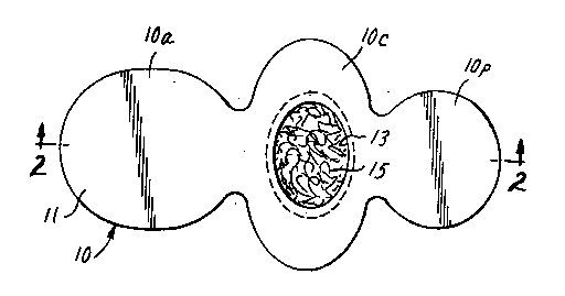
Turning first to FIGs . 1 and 2, wax guard 10 -
comprises thin, strong, flexible carrier membrane 11 having
attaching lobes 10a, 10p, and central lobe 10c, hole 13
being located approximately in the center of lobe 10c. One
side of carrier membrane 11 is provided with a layer of
20 normally tacky and pressure-sensitive adhesive 14, which
serves to affix wax guard 10 to a hearing aid, with hole 13
positioned over the sound outlet port of the hearing aid. A
nonwoven mat 15 of fine fibers is held in place by adhesive
14 in the area circumjacent to hole 13. If desired, hole
25 13 may be covered with a mesh fabric to help retain mat 15
in place.
Carrier membrane 11 is conveniently made from a
white rayon acetate taffeta woven backing, combined with a
layer of pressure-sensitive adhesive 14, the mild rugosity
30 of the backing imparting a desirable frictional property
when wax guards of the invention are used as subsequently
described. One adhesive-coated product suitable for use in
practice of the invention is available from Minnesota
Mining and Manufacturing Company (3M) under the catalog
35 designation "1538-L Woven Medical Tape on Liner." The ad~
hesive on this product is a hypoallergenic acrylate, making
it especially suitable for practicing the present inven- ~ ~
tion. 4 ~ ~-
W093/12626 PCT/~S92/10231
2122727 ~ ~
Nonwoven mat 15 is desirably formed from a melt-
blown mat of extremely fine oleophilic polypropylene
fibers. Alternatively, the mat could be an appropriately
sized disc formed from a web of oleophilic open cell foam.
Turning next to FIGs. 3 - 5, wax guard 30 com-
prises a thin, compressible, resilient, sound-transmitting,
soft membrane layer 31 of reticulated open cell microporous
foam. Wax guard 30 in turn comprises anterior and posteri~
or attaching lobes 30a, 30p, and central lobe 30c.
10 Laminated to the lower surface of foam membrane layer 31 is
double-coated tape 32, comprising thin (about 0.0015-inch,
or 6-micrometer) polyethylene film 33 and pressure-sensi-
tive adhesive layers 34, 35. Central portion 36 of lobe
30c is free from tape 32. Thus, whereas tape 32 seals foam
15 membrane 31 and destroys its sound-transmitting ability,
central portion 36 remains open and continues to retain
that ability. ThiS embodiment of the invention is thus
both simple and economical to make. ~ ;
Attention is now directed to FIG. 6, showing wax
20 guard 30 of FIG. 3 mounted on hearing aid 50. As is shown
in FIG. 6, human outer ear 40 comprises pinna 41, concha
42, ear canal 43, and ear drum 44. Positioned within the
outer portion of canal 22 is hearing aid 50, which includes
the conventional battery, microphone, amplifier, and speak-
25 er (none of which are shown)~ with open ended sound-trans-
mitting tube 51 extending from the speaker to the inner end
of hearing aid 50 and terminating in an outlet port. Wax
guard 30 is positioned so that area 36 (which, it will be
recalled, is free from pressure-sensitive adhesive tape) is
30 mounted over the outlet port of sound transmitting tube 51,
with adhesive-coated circumferential area 30c and lobes 30a --~
and 30p adhered, respectively, to the inner end and anteri-
or and posterior sides of hearing aid 50 to hold wax guard
30 in place. As previously pointed out,the outer portion
35 of canal 43 is oval rather than circular in cross section,
with the longer axis e~tending in a generally vertical
plane. This ovality is reflected in the shape of central
portion 31c of wax guard 30, and lobes 30a and 30p are ac-
cordingly intended to be mounted along the anterior and
40 posterior sides of hearing aid 50. This positioning also
-5-
,~ .
W093/12626 2 ~ 2 2 7 2 ~ PCTIUS92/1023h ;~
provides a somewhat snugger fit between hearing aid 50 andthe wall of canal 43 and helps hold hearing aid 50 in
place. This is especially important when chewing or talk-
ing causes the anterior wall of canal 43 to move in and
out, which in turn causes the anterior-posterior dimension
of the oval canal wall to contract and expand.
It will be noted that posterior attaching lobe
30p is smaller than anterior attaching lobe 30a, enablinq
it to conform easily to the concave posterior surface of
any hearing aid. This is especially important for those
hearing aids that are seated in concha 42, which do not ex-
tend to a great depth in canal 43 and have other plastic
surfaces that can interfere with easy access to the concave
posterior s:ide of the canal-occupying part of the hearing
aid.
Because foam membrane 31 is not only compress~
ible but also resilient, sealing of hearing aid 50 against
the wall of canal 43 can be maintained, even as the dimen-
sions of canal 43 change during mastication or conversa-
20 tion. This improved sealing helps correct the extremelyannoying feedback problem frequently encountered by hearing
aid wearers while dining with friends or talking on the
telephone, Xndeed~ it is contemplated by the inventor that
dif~erent thicknesses or surface areas of foam layer 31 can
25 be employed to achieve the desired result. Inasmuch as im-
proper fit is one of the most frequent complaints made by
persons who have just purchased hearing aids, it is be-
lieved that use of the wax guard of this embodiment of the
invention may reduce such complaints. With respect to the
30 improved sealinq provided by the foam, attention is direct~
ed to the prior art product ER-13R "E-A-R RING", a ring
formed from foam and intended to be slipped over the distal
portion of a hearing aid to "seal leaky shells" and reduce
feedback. Prior art devices of this type, which are avail-
35 able from Etymotic Research, Elk Grove Village, Illinois,USA, are not providzd with pressure-sensitive adhesive
(presumably because they would then be hard to install on a
hearing aid)t although the use of a dxop of a permanent
adhesive (e.g., tetrahydrofuran, which is presumably a sol-
40 vent for the hearing aid 50) is suggested. In the absence
~ 093/12626 PCT/US92/10231
2 1 2 2 7 2 7
of adhesive, these rings have been known to remain in the
ear canal after removal of the hearing aid, and if a strong
adhesive is used, it will be hard to remove the ring from
the hearing aid.
A currently preferred material for use as foam
layer 31 is a polyester urethane foam about 0.05 inch (l.3
mm) thick, having about lOO pores per lineal inch (40 pores
per lineal centimeter) and a void volume of about 97%. As
mentioned previously, however, somewhat greater thicknesses
may be appropriate for some individuals. This foam is also
oleophilic, which is considered advantageous for use as a
wax guard. Foams meeting these criteria are obtainable
from Foamex under the trade designation "SIF Filter Foam.~'
It is believed that a degree of stretchability
of the foam ~roduct just described is desirable in attain-
ing wrinkle-free conformance to hearing aids; thus, it may
be feasible to provide one surface of reticulated foam di-
rectly with an adhesive. Greater strength can be imparted,
however, by laminating the foam to a fine open mesh woven
or nonwoven fabric (either of which might cover hole 36,
86, 96 without in~erfering with sound transmission) or, as
in the product just described, to a double-coated tape.
Attention is now directed to FIG. 7, which de-
picts the manner in which wax guards of the invention can
be mounted for distribution to hearing aid dispensers or
wearers of "in the ear" hearing aids. Three wax guards 30,
80, 90 are shown removably mounted on a conventional sheet
of release liner 60, the adhesive-coated surface of
posterior attaching lobes 30p, 80p, 90p, and central lobe
30c, 80c, 90c being in contact with the release surface of
liner 60. Anterior attaching lobes 30a, 80a, 90a are lift-
ediabove the surface of release liner 60, with fold`ed rei-
lease liner 70 contacting the adhesive-coated surface of
lobes 30a, 80a, 90a. Liner 70 has two wings, 70a and 70b,
35 the adhesive-coated surface of lobes 30a, 80a, 90a being in
contact with wing 70a. When wax guard 30, 80, or 90 is to
be mounted on hearing aid 50, the distal portion of wing
70b is grasped (preferably along with lobe 30a, BOa, or
90a, as appropriate), and the remainder of wax guard 30,0 80, or 90, peeled from release liner 60. Center lobe 30c,
--7--
W093/~2626 2 ~ 2 2 7 2 7 p~T/US92/l023~3
80c, or 90c is then positioned over and circumferentially
adhered to the sound outlet end of hearing aid 50 and ex-
posed lobe 30p, 80p, or 90p then adhered to the posterior
side of hearing aid 50. Wing 70a of folded release liner
5 70 i~ then removed from lobe 30a, 80a, or 90a while the
latter is being adhered to the anterior side of hearing aid
50.
For convenience, the linered wax guard assembly
shown in FIG. 7 can be distributed in a transparent plastic
10 envelope 92, which will ensure that wax guards 30, 80, and
90 do not become prematurely detached from either liner 60
or fblded liner 70. It is contemplated that a kit contain-
ing a plurality of wax guards having a variety of thick-
nesses of reticulated open cell foam membrane 31, 81, 91
15 (e.g., 1/32, 1/16, and 1/8 inch, corresponding respectively
to about 0.8, 1.6, and 3.2 mm) will prove useful to hearing
aid dispensers, who can then provide the appropriate wax
guard for an individual hearing aid wearer. Alternatively,
as shown in ~IG. 7, this kit could consist of wax guards in
20 which anterior attaching lobes 30a, 80a, 90a are of differ-
ent dimensions
As still another alternative, single adhesive~
coated lobe~ of different dimensions could be incorporated
in a kit; although these lobes would not function as wax
25 guards, they could still be used to determine the appropri-
ate degree of sealing to reduce or eliminate feedback
caused by canal shape change resulting from jaw motion.
Once the appropriate size has been determined, the adhe-
sive-coated lobe could be used until it is soiled, after
30 which~it~would be replaced with a fresh lobe.~ It is fur-
ther contemplated that, when using the feedback suppressing
aspect of the invention, shape-retaining retar~ed recovery~
materials such as plasticized polyvinyl chloride (cf. U.S.
Pat. Re~. 29,487) or polyurethane (cf. U.S. PatO No.
35 4,880,076) would be more efficient than the open cell
reticulated foam used for wax entrapment and hence could be
used in thinner sections.
Those skilled in the art will readily appreciate
that the foregoing description is not intended to be ex~
40 haustive, and numerous variations of the invention can be
-8-
''..' '~' ~'.','
`
"~093/12626 ~ ~ 2122727 PC~/US92/1023
made without departing from the spirit of what has beentaught. ~hus, for example, although wax guards having two
attaching lobes are currently preferred, it would be feasi-
ble to have four, the additional lobes attaching to the su-
5 perior and inferior surfaces of the hearing aid. Thegreater the number of lobes, however, the greater the dif-
ficulty in attaching the wax guard. It should be possible
to prepare a wax guard having a single attaching lobe
(preferably the anterior lobe), the adhesive border on the -
lO center lobe holding it in place over the sound outlet port.
It may also be possible to prepare a product that has a
single continuous lobe, resulting in a construction~ resem-
bling that of a condom.
Similarly, the utility of the invention is not
15 limited to hearing aids, but is readily adaptable to any
type of sound transmitting device that intrudes into the
ear canal.
At the present time, the preferred dimensions of
wax guard 30 are about 18.5 mm from the distal end of lobe
2~ 30a to the distal end of lobe 30p, lobe 30a being about 7.4
mm long and 6.6 mm wide. Lobe 30p is abou~ 4.8 mm long and ;-
5.6 mm wide. Central lobe 30c is about 8.9 mm wide. -~
Although these exact dimensions and shapes are not criti~
cal, such products are suitable for mounting on all known
25 "in the ear" hearing aids. wa~ guards having the shape of
wax guard lO are useful on most hearing aids, although they
may be somewhat difficult to install smoothly on hearing
aids that fit into concha 42 and do not penetrate as far
into canal 43 as hearing aids that fit almost entirely into
30 canal 43. -;~
Although numerous pressure-sensitive adhesives may be
used to mount wax guard l0 or 30 on hearing aid S0, acry- -
late types are presently preferred; acrylate adhesives
(e.~., a 95:5 isooctyl acrylate:acrylic acid copolymer) ad-
35 here well to the acrylate polymers used to make most hear-
ing aids. Acrylate adhesives also tend not to irritate
skin with which they may come in contact.
9 ~,