Note: Descriptions are shown in the official language in which they were submitted.
- ~ 2123032
A SHRINK FILM WRAPPER
TECHNICAL FIELD
The present invention relates to a method for shrink film wrapping of
5 one or more objects, in which two film webs - a first and a second web - are
sealed together with the aid of a sealing device, and in which the objects
are fed in towards the jointly sealed film webs by means of a pusher in one
or more rows, whereafter the film webs are once again sealed together,
severed and caused to surround the objects. The present invention also
1 0 relates to an apparatus for carrying the method into effect.
BACKGROUND ART
A method common within the packaging industry for arranging
distribution units is to shrink film wrap one or more objects together into a
15 distribution unit which is appealing to the consumer. Hitherto, the shrink film
wrapped objects have been wrapped by one or two film lengths into a loose
banderol which, in a subsequent process, passes a hot air furnace where
the film banderol is inflated by the hot air, whereafter the film shrinks about
the objects. This method has entailed a relatively large material
20 consumption of film, since the shrinkage has been difficult to calculate and
a relatively large margin of film must be catered for. Furthermore, the
shrinking operation has entailed that the film has formed folds and holes in
the shrinking process. The wish within the art to provide such a shrink film
with some form of printed artwork decor has consequently proved difficult to
25 realise without distortion.
OBJECTS OF THE INVENTION
One object of the present invention is to realise a method for shrink
film wrapping in which there is obtained an attractive and neat distribution
~0 package without the above-outlined problems.
A further object of the present invention is to reduce material
consumption and make possible the employment of a thinner film.
Yet a further object of the present invention is to realise a distribution
unit in which it is possible to use a pre-printed film.
~5
- ` 2123032
SOLUTION
These and other objects have been attained according to the present
invention in that the method of the type disclosed by way of introduction has
been given the characterizing features that both of the films are retained
5 and stretched by the movement of the pusher; that the first film is retained
and finally stretched by the movement of the sealing device; and that parts
of the film projecting outside the objects to be wrapped are subjected to
thermal action.
Preferred embodiments of the present invention have further been
l 0 given the characterizing features as set forth in the appended subclaims.
BRIEF DESCRIPTION OF THE ACCOMPANYING DRAWINGS
One preferred embodiment of the present invention will now be
described in greater detail hereinbelow, with particular reference to the
l5 accompanying Drawings, in which~
Figs. 1 to 3 show a sequence of the method of the present invention,
in a schematic version.
The Drawings show only those details essential to an understanding
of the present invention, the placing of the equipment employed in its
20 context (which is well known to a person skilled in the art) having been
omitted.
..
DESCRIPTION OF PREFERRED EMBODIMENT
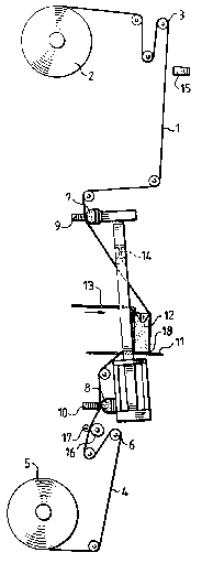
The apparatus for realising a shrink film wrapping according to the
25 present invention consists of a first film web 1, hereafter designated the
upper film which, from a magæine reel 2, is passed via a number of
bending rollers 3 through the apparatus to the point where it merges with a
second film web 4, hereafter designated the lower film web. The lower film
web 4 also departs from a magæine reel 5 and is brought, via a number of
~0 bending rollers 6, to merge with the first film web 1.
Both of the film webs 1 and 4 each pass a hose brake 7, 8 on their
way through the apparatus. Each hose brake 7, 8 consists of an elongate
hollow body which can intermittently be inflated with air and deflated. An
abutment 9, 10 acts against this hollow body so that, when the hollow body
~5 is inflated with air, the film webs 1, 4 are held fast against this abutment 9,
10, and when the hollow body is deflated, the film webs 1, 4 can once again
~ ~ -
2123032
..
:.
freely pass. The film web 1, 4 may also be released in that the abutment 9,
10 is moved away from the inflated hollow body.
At that point where both of the film webs 1, 4 merge together, there is
provided a sliding plate 11 where the objects 12 intended for shrink film
wrapping are fed in. The objects 12 are fed in by means of a pusher 13.
In connection with the sliding plate 11, there is also provided a
sealing jaw 14 which is movable in the vertical plane for sealing both of the
film webs 1, 4. The sealing jaw 14 slopes at an angle of approx. 5 - 10 from
the vertical. This inclination is arranged such that the sealing jaw 14 will be
l 0 able to approach more closely to the objects 12 which are to be surrounded
by the film webs 1, 4.
All of the parts included in the apparatus, i.e. hose brakes 7, 8,
pusher 13 and sealing jaw 14 are mechanically interconnected with one
another, eg. by means of cams so that they cooperate synchronously in a
predetermined working cycle. Cams and the mechanical connection
components are not shown on the Drawings. .
The apparatus may moreover include a photocell 15 placed at the
upper film web intended intended for decor or artwork register maintenance
of artwork pre-printed on the upper film web 1. In order to make possible the
employment of artwork maintenance on the upper film web 1, the lower film
web 4 is simultaneously provided with a drive roller 16 which can be locked
and released intermittently. The drive roller 16 drives the film 4 which is
nipped against a counter roller 17. Driving of the drive roller 16 is engaged
and disengaged by means of a clutch/brake.
At the starting position for shrink film wrapping of one or more objects -~
12, both of the film webs 1, 4 are brought together and sealed to form a first
joint or seam. As is shown in Fig. 1, the pusher 13 moves a number of
objects 12 marshalled in a row so that their one lower corner 18 is placed
against the joint or seam of the two film webs 1, 4. In such instance, the
objects 12 will stand on the lower film web 4, while the common longitudinal
side of the objects moves towards the upper film web 1. Just before the
pusher 13 has completed its advancement of the objects 12 and returned to
its rear position, the two hose brakes 7, 8 are activated, these being
disposed on each respective film web 1, 4. At this point, both of the film
~5 webs 1, 4 are locked in that the abutments 9, 10 are moved towards the
inflated hollow bodies and the remaining distance of the forward stroke of
--. 2123~2
the pusher 13 thereby stretches both of the film webs 1, 4 so that they tightly
abut against the common longitudinal side of the objects 12. If shrink film
wrapping of several rows of objects 12 is desired, the hose brakes 7 and 8
are not activated until on insertion of the last row of objects 12. This is
5 effected in that the hollow body at the first rows is deflated and is inflated on
insertion of the last row of objects 12.
Simultaneously with the return stroke of the pusher 13, a top support
19 descends and fixedly retains the objects 12 in a position where the -
pusher 13 has stretched the film webs 1 and 4 so that they lie stretched i
l 0 against the objects 12. The top support 19 fixedly retains the objects 12 in this position and the hose brakes 7 and 8 are deactivated in that the
abutments are displaced away from the inflated hollows bodies, as shown
in Fig. 2, and the film webs 1, 4 may freely pass. :-
The sealing jaw 14 thereafter executes its downward stroke as
l 5 illustrated in Fig. 3. Just before the sealing jaw 14 descends to the sliding
plate 11, the upper hose brake 7 is once again activated in that the
abutment 9 is moved via a cam towards the inflated hollow body so that the
sealing jaw 14, in Us remaining downward stroke, finally stretches the upper
film web 1 against remaining sides of the wrapped objects 12. Both of the
film webs 1, 4 are sealed together to form a sealing joint or seam consisting
of two parallel seams. and the now wrapped row of objects 12 is severed
from the film webs 1, 4 between the two parallel sealing joints or seams.
At this point, the apparatus is back at the starting position and the
cycle is repeated. The ready-wrapped objects 12 are moved further through
the apparatus where the parts of the film 1, 4 projecting outside the objects : ~ -
12 are exposed to thermal action by means of hot air nozzles (not shown).
When use is made of an upper film 1 provided with pre-printed
artwork, an unprinted lower film 4 is employed at the same time. The upper,
pre-printed film 1 has so-called artwork markings which occur at regularly
~0 recurring spacing, which can be read-off by means of a photocell 15. The
distance between the artwork markings is slightly greater than the
calculated consumption for wrapping the intended objects 12.
After sealing together of the two film webs 1, 4, when the sealing jaw
14 executes its upwardly directed stroke, the photocell 15 reads-off the
artwork marking. When this does not lie in register with the photocell 15, the
artwork register maintenance is adjusted in that the two united film webs 1, :
2123032
4 are drawn downwards into the correct position. Given that the distance
between the artwork markings is slightly greater than the intended
consumption of film material, this entails that the lower film web 4 is drawn,
this being sealed together with the upper film web 1 so that the artwork
S marking can be read-off by the photocell 15. The lower film web 4 is drawn
down in that the drive roller 16 is locked by means of, for example, a
clutch/brake against a counter roller 17. After the compensation of the
artwork register maintenance is completed, the drive roller 16 is re-
released, the counter roll~r 17 is moved aside and the lower film 4 can
l 0 freely pass the drive roller 16.
As will have been apparent from the foregoing description, the
present invention realises a shrink film wrapping which produces
attractively and neatly wrapped objects, making possible the employment of
film webs carrying artwork decor. With a shrink film wrapping method and
l 5 apparatus according to the present invention, film consumption is reduced
by between 30 and 35% and it is also possible to use a thinner film, since
the above-described method largely employs the tensile strength and
extensibility of the film which is supplemented with a final shrinking of
residual film.
The present invention should not be considered as restricted to that
described above and shown on the Drawings, many modifications being
conceivable without departing from the spirit and scope of the appended
Claims.