Language selection

Search

Patent 2123161 Summary

Third-party information liability

Some of the information on this Web page has been provided by external sources. The Government of Canada is not responsible for the accuracy, reliability or currency of the information supplied by external sources. Users wishing to rely upon this information should consult directly with the source of the information. Content provided by external sources is not subject to official languages, privacy and accessibility requirements.

Claims and Abstract availability

Any discrepancies in the text and image of the Claims and Abstract are due to differing posting times. Text of the Claims and Abstract are posted:

  • At the time the application is open to public inspection;
  • At the time of issue of the patent (grant).
(12) Patent: (11) CA 2123161
(54) English Title: DOUBLE-PISTON PUMP FOR ADMINISTERING MEDICATION
(54) French Title: POMPE A PISTON DOUBLE POUR L'ADMINISTRATION DE MEDICAMENT
Status: Term Expired - Post Grant Beyond Limit
Bibliographic Data
(51) International Patent Classification (IPC):
  • A61M 05/175 (2006.01)
  • A61M 05/142 (2006.01)
  • F04B 03/00 (2006.01)
  • F04B 09/02 (2006.01)
(72) Inventors :
  • HUGGENBERGER, HEINZ (Switzerland)
(73) Owners :
  • MEDIMPEX ETS.
(71) Applicants :
  • MEDIMPEX ETS. (Liechtenstein)
(74) Agent: MARKS & CLERK
(74) Associate agent:
(45) Issued: 2005-03-15
(22) Filed Date: 1994-05-09
(41) Open to Public Inspection: 1994-11-11
Examination requested: 2000-05-02
Availability of licence: N/A
Dedicated to the Public: N/A
(25) Language of filing: English

Patent Cooperation Treaty (PCT): No

(30) Application Priority Data:
Application No. Country/Territory Date
01 432/93-7 (Switzerland) 1993-05-10

Abstracts

English Abstract

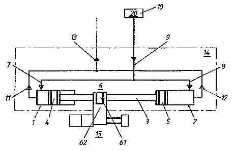
The device of the invention provides preselected doses of liquid medicine and has a cylinder assembly (1, 2) with a left cylinder (1), a right cylinder (2) and a double piston (4, 5) displaceably mounted in the assembly with a left piston end (4) and a right piston end (5). A coupling links the double piston in a positive and/or frictional manner with a drive unit (15). The device is controlled passively by two automatically closing intake valves (7, 8) and two discharge valves (11, 12). Thereby a continuous flow of liquid medicine 20 out of the medicine container 10 can be generated.


French Abstract

Le dispositif de l'invention fournit des doses présélectionnées de médicaments liquides et possède un ensemble de cylindre (1, 2) avec un cylindre gauche (1), un cylindre droit (2) et un double piston (4, 5) montés de manière déplaçable dans l'ensemble avec une extrémité gauche du piston (4) et une extrémité de piston droite (5). Un accouplement relie le double piston d'une manière positive et/ou par friction avec une unité d'entraînement (15). Le dispositif est contrôlé passivement par deux soupapes d'admission à fermeture automatique (7, 8) et deux soupapes de décharge (11, 12). De ce fait un flux continu d'un médicament liquide 20 du récipient 10 à médicament peut être généré.

Claims

Note: Claims are shown in the official language in which they were submitted.

The embodiments of the invention in which an exclusive
property or privilege is claimed are defined as follows:
1. A device for administering doses of liquid medicine of
predetermined quantity, the device comprising a combination
of:
right and left cylinders;
a substantially constant speed and force linear drive
unit;
a double-ended piston having left and right piston ends,
displaceably mounted in said left and right cylinders,
respectively;
means for coupling said double-ended piston to said drive
unit; and
a pair each of automatically opening and closing intake
valves and discharge valves, for passively controlling
operation of said device.
2. A device according to claim 1, wherein said valves
include:
a left intake valve for said left cylinder and a right
intake valve for said right cylinder, the intake valves
being connectable by an intake line to a medicine
container;
a left discharge valve for said left cylinder and a right
discharge valve for the right cylinder, the discharge
valves supplying liquid medicine through a discharge line.
3. A device according to claim 2, and including a piston
rod rigidly interconnecting said left piston end and said
right piston end, the piston ends being displaceable in the
same direction in said two cylinders.
7

4. A device according to claim 3, wherein said means for
coupling said double-ended piston to said drive unit is
mounted on said piston rod.
5. A device according to claim 4, wherein said means
mounted on said piston rod for coupling said piston to said
drive unit includes a drive disk.
6. A device according to claim 4, wherein said means
mounted on said piston rod for coupling said piston to said
drive unit includes a non-rotatable threaded spindle, and
an internally-threaded gear engaging said spindle and
rotated by said drive unit.
7. A device according to any one of claims 1 to 6,
wherein said intake valves and said discharge valves are
elastomeric bodies sealed passively.
8. A device according to any one of claims 1 to 7,
wherein said drive unit comprises a spindle and a nut
threaded on that spindle.
9. A device for administering doses of liquid medicine of
predetermined quantity, the device comprising the
combination of:
right and left cylinders;
a drive unit;
a double-ended piston having left and right piston ends,
displaceably mounted in said left and right cylinders,
respectively;
means for coupling said double-ended piston to said drive
unit;
8

a pair each of automatically opening and closing intake
valves and discharge valves, for passively controlling the
operation of said device; and
means for joining said cylinders, said double-ended
piston and said valves into a pump unit detachably coupled
to said drive unit.
10. A device according to claim 9, and including a piston
rod rigidly interconnecting said left piston end and said
right piston end, the piston ends being displaceable in the
same direction in said cylinders.
11. A device according to claim 9, wherein said double-
ended piston includes a piston rod between said piston
ends, and wherein said means for coupling said double-ended
piston to said drive unit is mounted on said piston rod.
12. A device according to claim 9, 10 or 11, and including
a medicine container containing the liquid medicine for
dispensing, and a snap-on cap on the container for
irreversibly securing against a patient's removal of liquid
medicine from the medicine container.
13. A device according to any one of claims 9 to 12,
wherein said pump unit is assembled from injection-molded
parts.
9

Description

Note: Descriptions are shown in the official language in which they were submitted.


CA 02123161 2004-05-31
DOUBLE-PISTON PUMP FOR ADMINISTERING MEDICATION
This invention concerns a device for administering a
dose of preselected quantity of liquid medicine to a
patient, or a sequence of such doses.
German Laid-Open Publication DE 40 16 306 A1,
published November 28, 1991, discloses a radial piston pump
to supply small amounts of liquid, in which two
independent pump pistons are driven in mutually opposite
directions and implement conveyance of the liquid through
control valves. This know radial pump has the drawbacks of-_
inherent high transverse forces and entailed friction, and
also requires high manufacturing accuracy of the
cooperating radial disks.
An object c>f the invention is to provide an improved
dosing apparatus, and specifically an easily handled device
to supply a preselected dose of liquid medicine and permit
accurate dispensing and variation of the medicine dose.
In accordance with this invention a device for
administering doses of liquid medicine of predetermined
quantity comprises a combination of: right and left
cylinders; drive unity a double-ended piston having left
and right piston ends, displaceably mounted in the left and
right cylinders, respectively; means for coupling the
double-ended piston to the drive unit; and a pair each of
automatically opening and closing intake valves and
discharge valves,. for passively controlling operation of
the device.

CA 02123161 2004-05-31
Some advantages achieved by the invention are:
--because of the double piston, the system does not
experience a partial vacuum, and a steady flow of medicine
takes place in operation;
--because the pump unit and the drive unit are separate and
easily and quic~:ly can be joined together, handling is
simple and patient-friendly;
--dispensing quality is determined by the pump itself,
rather than by external parameters such as pressure,
temperature, humidity and the like;
--changes in medicine doses can be present by pump-unit
parameters (piston diameter) and the pitch of the thread of
the piston rod; as a result, a corresponding standard set
of pump units can be set up;
--the drive unit can be used for a substantial time, i.e.,
it may be used for several medicine containers of one
patient;
--the pump unit is designed as a one-way system for single
use.
The drawings show an illustrative embodiment of the
invention together with the principle of its operation,
which will be described with reference to the following
drawings wherein:
Fig. 1 is a simplified schematic drawing of a device
in accordance with the invention;
Fig. 2 is a modified detail of the device of Fig. 1;
and
2

212316
Fig. 3 is a sectional view of a device in accordance with
the invention.
Description of the Preferred Embodiments
The device shown in Figs. 1 through 3 serves to dispense a
preselected dose of a liquid medicine and comprises a pump unit
14 connected to a medicine container 10.
Pump unit 14 comprises a double cylinder assembly having a
left cylinder 1 and a right cylinder 2 formed in bodies 22 and
22', respectively, which cylinders receive the opposite ends of a
double piston with displaceable left and right piston ends 4 and
5, respectively. The left and right piston ends 4 and 5 are
rigidly joined together by a piston rod 3 and the piston ends are
slideably mounted in the two cylinder parts 1, 2 so as to be
reciprocatingly displaceable together in the same direction.
Coupling means 6 is provided at the piston rod 3 and includes a
drive disc 61 coupled to a drive fork 62 which links the piston
rod to a drive unit 15 for mechanical driving. In the embodiment
of Fig. 1, drive 15 includes a drive motor with an output shaft
moving fork axially with respect to piston rod 3, thereby also
moving the piston rod axially. However, the pistons in cylinders
1, 2 may also be displaced inductively by coupling a coil to the
piston rod or an associated component, not shown.
Liquid flow in the pump is controlled in a wholly passive
manner by means of two automatically closing intake valves 7 and
8 and two discharge valves 11 and 12. For that purpose a left
intake valve 7 is provided for the left cylinder part 1 and a
right intake valve 8 for the right cylinder part 2, the two
intake valves 7, 8 being connectable by intake lines 9 to a
medicine container 10 containing medicine 20. A left discharge
valve il is provided for the left cylinder 1 and a right
discharge valve 12 for the right cylinder 2, the two discharge
valves 11, 12 supplying the liquid medicine 20 through a
3

~1 ?'~~ ~1
discharge line 13. Discharge line 13 is isolated from the
external atmosphere by a pierceable membrane 16 through which may
pass a catheter or cannula. Intake line 9 is similarly isolated
from the external atmosphere by a pierceable membrane 17 which is
covered by a snap-on cap 18 to prevent the patient removing
liquid medicine 20 from medicine container 10.
Medicine container 10 contains a pouch 19 the interior of
which is practically at vacuum when supplied. It is enough to
pierce the membrane 17 using a syringe to fill pouch 19 through
intake line 9 with liquid medicine 29. Thereafter, the pierced
membrane 17 is securely closed by snap-on cap 18.
The automatic-control intake valves 7, 8 and the parts of
the intake line 9 which are around them are sealed by a semi-
cylindrical rubber mat 23 from the two bodies 22 and 22' in which
cylinders 1, 2 are formed. Mat 23 is formed with peripheral
sealing ribs to permit communication between lines 9 but to
prevent flow of liquid elsewhere. Similarly, automatic-control
discharge valves 11, 12 and the parts of discharge line 13
around them are sealed by a rubber mat 21, shaped like mat 23,
from bodies 22 and 22' of the cylinder 1, 2. In practice, valves
7 and 8 and mat 23 are made as a single body of resilient,
elastomeric material having the central portion performing the
sealing function of mat 23 and the end portions performing the
valving functions. Mat 21 and valves il and 12 are similarly
joined. The two rubber mats 21 and 23 therefore act as seals and
valves.
A complete cycle of operation of pump unit 14 will now be
described with reference to Fig. 3.
Fig. 3 shows the initial state wherein the two intake~valves
7 and 8, and also the two discharge valves 11 and 12, are
normally closed due to slight over-dimensioning of the resilient
valve material. In a first step, double piston 4, 5 is moved to
the left. This displacement of the double piston 4, 5 is by
induction or else, as described above with reference to Fig. 1,
4

~123I~1
is mechanical and is driven by means 6 coupled to piston rod 3.
Discharge valve 12 remains closed but intake valve 8 is opened by
a partial vacuum generated in right cylinder part 2, as a result
of which liquid medicine 20 is sucked out of pouch 19 through
S intake line 9 into right cylinder part 2.
Simultaneously, intake valve 7 remains closed by the
combined forces of the pressure generated in left cylinder part 1
and the suction in intake line 9, while the discharge valve 11 is
opened by that pressure so that any air in the left cylinder part
1 is expelled through the discharge line 13 (by means of a
catheter piercing the membrane 16).
In a second operating step after the double piston 4, 5 has
reached its left end position, the piston is moved to the right
again. This movement causes discharge valve 11 to be closed and
intake valve 7 to open so that the liquid medicine 20 is sucked
out of pouch 19 through intake line 9 into left cylinder chamber
1, while simultaneously intake valve 8 is closed and discharge
valve 12 opened. The liquid medicine 20 which was sucked during
the first phase into right cylinder chamber 2 is expelled through
~' 20 discharge line 13 past closed discharge valve 11 (by a catheter
piercing membrane 16).
After the double piston 4, 5 has reached its right end
position, it is again displaced to the left and the sequence of
the first step is repeated, with the single difference that
I 25 liquid medicine 20 is expelled from left cylinder chamber 1
' rather than air.
In this manner the ganged right-left motion of the double
piston 4, 5 implements repeated expulsion of liquid medicine 20
through the automatic valves 7, 8; 11, 12. The device thus
30 delivers small doses at regular intervals which can be preset to
' occur, for example, between 30 seconds and 10 minutes. Taking
into consideration the relatively slow uptake of medication into
the human body, choosing the shortest intervals results in
delivery of medication which is substantially continuous.
S

212361
Fig. 2 shows an alternative delivery drive in which piston
rod 3 is externally threaded or carries an externally threaded
non-rotatable spindle 63 surrounded by an internally threaded,
externally toothed gear 62. Gear 62 engages teeth on a gear 64
coupled to the output shaft of drive motor 15. When the output
shaft of the motor rotates, gear 62 also rotates and the engaged
threads cause spindle 63 to move axially somewhat in the manner
of a nut, thus driving piston rod 3 and the pistons to dispense
medication as described above.
6

Representative Drawing
A single figure which represents the drawing illustrating the invention.
Administrative Status

2024-08-01:As part of the Next Generation Patents (NGP) transition, the Canadian Patents Database (CPD) now contains a more detailed Event History, which replicates the Event Log of our new back-office solution.

Please note that "Inactive:" events refers to events no longer in use in our new back-office solution.

For a clearer understanding of the status of the application/patent presented on this page, the site Disclaimer , as well as the definitions for Patent , Event History , Maintenance Fee  and Payment History  should be consulted.

Event History

Description Date
Inactive: Expired (new Act pat) 2014-05-09
Inactive: IPC from MCD 2006-03-11
Grant by Issuance 2005-03-15
Inactive: Cover page published 2005-03-14
Pre-grant 2004-12-16
Inactive: Final fee received 2004-12-16
Notice of Allowance is Issued 2004-09-27
Letter Sent 2004-09-27
Inactive: Approved for allowance (AFA) 2004-09-15
Amendment Received - Voluntary Amendment 2004-05-31
Inactive: S.29 Rules - Examiner requisition 2003-12-02
Inactive: S.30(2) Rules - Examiner requisition 2003-12-02
Amendment Received - Voluntary Amendment 2000-10-31
Letter Sent 2000-05-15
Inactive: Status info is complete as of Log entry date 2000-05-15
Inactive: Application prosecuted on TS as of Log entry date 2000-05-15
All Requirements for Examination Determined Compliant 2000-05-02
Request for Examination Requirements Determined Compliant 2000-05-02
Application Published (Open to Public Inspection) 1994-11-11

Abandonment History

There is no abandonment history.

Maintenance Fee

The last payment was received on 2004-04-19

Note : If the full payment has not been received on or before the date indicated, a further fee may be required which may be one of the following

  • the reinstatement fee;
  • the late payment fee; or
  • additional fee to reverse deemed expiry.

Patent fees are adjusted on the 1st of January every year. The amounts above are the current amounts if received by December 31 of the current year.
Please refer to the CIPO Patent Fees web page to see all current fee amounts.

Owners on Record

Note: Records showing the ownership history in alphabetical order.

Current Owners on Record
MEDIMPEX ETS.
Past Owners on Record
HEINZ HUGGENBERGER
Past Owners that do not appear in the "Owners on Record" listing will appear in other documentation within the application.
Documents

To view selected files, please enter reCAPTCHA code :


To view images, click a link in the Document Description column (Temporarily unavailable). To download the documents, select one or more checkboxes in the first column and then click the "Download Selected in PDF format (Zip Archive)" or the "Download Selected as Single PDF" button.

List of published and non-published patent-specific documents on the CPD .

If you have any difficulty accessing content, you can call the Client Service Centre at 1-866-997-1936 or send them an e-mail at CIPO Client Service Centre.

({010=All Documents, 020=As Filed, 030=As Open to Public Inspection, 040=At Issuance, 050=Examination, 060=Incoming Correspondence, 070=Miscellaneous, 080=Outgoing Correspondence, 090=Payment})


Document
Description 
Date
(yyyy-mm-dd) 
Number of pages   Size of Image (KB) 
Representative drawing 1998-05-28 1 7
Representative drawing 2003-11-27 1 8
Claims 1995-03-24 3 115
Description 1995-03-24 6 278
Claims 2004-05-30 3 95
Abstract 1995-03-24 1 16
Drawings 1995-03-24 2 47
Description 2004-05-30 6 218
Acknowledgement of Request for Examination 2000-05-14 1 178
Commissioner's Notice - Application Found Allowable 2004-09-26 1 160
Correspondence 1994-11-06 1 32
Correspondence 2004-12-15 1 30
Fees 2006-05-02 1 26
Fees 1997-03-17 1 54
Fees 1996-03-04 1 48