Note: Descriptions are shown in the official language in which they were submitted.
- l - TN-A824/PCT
~ 2~3~
DESCRIPTION
Air Bag Provided With Reinforcing Belts
TECHNICAL FIELD
~he present invention relates to an air bag provided
with reinforcing belts. More particularly, the present
invention relates to an air bag provided with reinforcing
belts and having a high burst strength.
BACKGROUND ART
Recently, air bag systems have become practically
employed as a safety device for protecting the occupants
of an automobile. Usually, an air bag which was produced
by coating a surface of a smooth woven fabric with a
chloxoprene rubber or silicone rubber, cutting the coated
fabric into a circular form, superposing two cut fabric
pieces, namely circular top and bottom cloths, on each
other, seam-joining them a-t the circumferential edge
portions thereof, and attaching reinforcing belts
(straps) to the top and bottom cloths, is used.
Since the air bag is used by inflating it with a gas -
blown in an instant thereinto, the air bag is required to ~ :-
have no risk of bursting by a rapid raising of the inside
pressure thereof, namely a high burst strength. In the
air bag provided with the reinforcing belts, the bursting
of the air bag is mainly localized and occurs at the
connecting portions of the belts and the air bag. To
prevent this bursting, various attempts have been made.
For example, J~panese ~.x~m;ned Patent Publication
(Kokoku) No. 58-41216 discloses that an elastic material
such as a bias cloth has been used for the belts.
Also, Japanese Unexamined Patent Publication (~okai)
No. 1-12;2,751 discloses that reinforcing fabric pieces
have been arranged so as to bridge the main air bag
portion (a top cloth and a bottom cloth3 and the belts
and join ~he main air bag portion with tha belts through
the reinforcing fabric pieces.
Further, Japanese Un~mined Patent Publication
- 2 ~ 21~3~2~
''\ (Kokai) No. 3-164,34~ discloses that the main air bag
portion has been seam-joined to a belt catcher in a
direction at right angles to the longitudinal center line
direction of the belt.
Furthermore, in Japanese Unexamined Patent
Publication No. 3-248,945, in accordance wi-th the same
thinking as in Japanese Unexamined Patent Publication
No. 3-164,349, the main air bag por-tion and the belt
catcher axe seam-joined to each other along a straight
li.ne in a direction at right angles to the longitudinal
center 1.ine direction of the belt, and t~is seam is made
in a smaller seaming pitch than that in another portion
of the air bag.
Nevertheless, the a~ove-mentioned prior arts did not
satisfactorily enhance the burst strength, and thus a
further enhancement of the burst strength is strongly
demanded. Especially, in light weight, compact air bags
which are in recent strong demand, development of air
bags provided with reinforcing belts and having an
excellent burst strength is strongly required.
DISCLOSURE OF THE INVENTION
An object of the present invention is to provide an
air bag provided with reinforcing belt and having a high
burst strength when inflated.
The air bag of the present invention provided with
reinforcing belts comprises~
a substantially circular top cloth formed from
a woven fabric;
a substantially circular bottom cloth formed
from a woven fabric, superimposed on and seam-ioined to
the circular top cloth at the circular circumferential
edge portions thereof, and having a circular hole formed
- ' in the center portion of the bottom cloth, through which
hole an inflator can be joined to the air bag;
a top reinforcing cloth located in and seam- ~:
joined to the center portion of the circular top cloth
and comprising at least one wo~en fabric piece;
- 3 - 2 ~2~2~
a bottom reinforcing cloth located on and seam-
joined to a portion around the inflator~joining circular
hole of the circular bottom cloth, and comprising at
least one woven fabric piece; and
a plurality of reinforcing belts arranged on
the inside face of -the circular top cloth and on the
inside face of the circular bottom cloth and each
comprising at least one woven fabric piece, and
is characterized in that:
an end portion of each of the reinforcing belts
is connected -to one of the top reinforcing cloth and a .. -
top belt catcher seam-joined to the top cloth and ~ -
comprising at least one woven fabric piece, and an
opposite end por~ion of each of the reinforcing belts is
connected to one of the bottom reinforcing cloth and a
bottom belt catcher seam-joined to the bottom cloth and
comprising at least one woven fabric piece;
the top and bottom reinforcing cloths or the
top and bottom reinforcing cloths and the top and bottom
belt catchers are respectively seam-joining to portions
around the centers of the circular top and bottom cloths ~
by a plurality of concentrically closed seam lines; .. ~:-
a closed outermost circumferential seam line of
at least one of the top and bottom reinforcing clothes
and each o~ the reinforcing belts satisfy the
relationship ~
0.45 ~ ~L < 2.9~ (I)
wherein, ~ represents a shortest straight line distance
between two points at which a straight line drawn through -
a center of at least one of the circular top and bottom
cloths, having the closed outermost circumferential seam
line, intersects the outermost circumferential closed
seam line, and L represents a straight line distance
between an intersecting point of a longi~udinal center ::
line of the reinforcing belt with the outermost
circum~erential closed seam line of the top reinforcing .~.
cloth and an intersecting point of the longitudinal ~ ~
2 ~ 2 3 ~ 2 ~
.
center line of the reinforcing belt with the outermost
circumferential closed seam l;ne of the bot-tom
reinforcing cloth, measured along the longitudinal center
line.
S BRIEF DESCRIPTION OF 'rHE DRAWINGS
Figure lA is an explanatory view of an inside face
of a top cloth of an embodiment of a conventional air bag
provided with reinforcing belts, when turned inside out
before being inflated,
Fig. lB is an explanatory view of an inside face of
a bottom cloth of the conventional air b~g of Fig. lA
turned inside out,
Fig. lC is an explanatory cross-section of the
conven-tional air bag of ~igs. 1~ and lB when inflated,
showing arrangements and seam-joints of reinforcing
clothes and rein~orcing belts,
Fig. 2A is an explanatory view of ~n inside face of
a top cloth of an embodiment of the air bag of the
present invention provided with reinforcing belts, when
turned inside out before being inflated,
Fig. 2B is an explanatory view of an inside face of
a bottom cloth of the air bag of Fig. 2A, when turned
inside out,
Fig. 2C is an explanatory cross-section of the air
bag of Figs. 2A and 2B, when inflated, showing
arrangements and seam joints of reinforcing clothes and
reinforcing belts,
Fig. 3A is an explanatory view of an inside face of
a tGp cloth of another embodiment of the air bag of the
present invention provided with reinforcing belts, when
turned inside out before being inflated,
Fig. 3B is an explanatory view of an inside face of
a bottom cloth of the air bag of Fig. 3A, when turned
inside out,
Fig. 3C is an explanatory cross~section of the air
bag of Figs. 3A and 3B, when inflated, showing
arrangements and seam joints of reinforcing cloths and
_ 5 2~23~2~
reinforcing belts~
Fig. 4A is an explanatory view of an inside face of -
a top cloth of still another embodiment of the air bag of
the present invention provided with reinforcin~ belts, ~ --
when turned inside out: befora being inflated,
Eig. 4B is an explanatory view of an inside face of
a bottom cloth of the air bag of Fig. 4A, when turned
inside out,
Fig. 5A is an explanatory view of inside face of a
top cloth of still another embodiment of the air bag of
the present invention provided with rein~orcing belts,
when turned inside out before being inflated,
Fig. 5B is an explanatory view of an inside face of
a bottom cloth of the air bag of Fig. 5A, when ~urned
inside out,
Fig. 5C is an explanator~ cross-section of the air
bag of Figs. SA and 5B, when inflated, showing
arrangements and seam joints of reinforcing cloths and
reinforcing belts,
Fig. 6A is an explanatory view of an inside face of
a top clo~h of further another embodiment of the air bag
of the present invention provided with reinforcing belts,
when turned inside out before being inflated,
Fig. 6B is an explanatory view of an inside face of
a bottom cloth of the air bag of Fig. 6A~ when turned
inside out,
Fig. 6C is an explanatory cross-section of the air -~
bag oE Figs. 6A and 6B, when inflated, showing
arrangements and seam joints of reinforcing cloths and
reinforcing belts and belt catchers. -~
DESCRIPTION OF THE PREFERRED EMBODIMENTS
To make clear the characteristics in constitution
! and effects of the air bag of the present invention
provided with reinforcing belts, first, a conventional ~-
aix bag having reinforcing belts will be explained below.
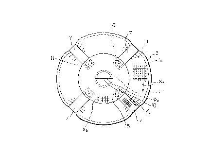
A conventionàl air bag provided with reinforcing
belts, as shown in Figs. lA, lB and lC, comprises a top
- 6 - 2~23~2~
clo~h 1 formed from a woven fabric piece cut into a
substantially circular form, and a ~ottom cloth 2 formed
from a woven fabric piece cut into a substantially
circular form. The circular top cloth 1 and the circular
bottom cloth 2 are superimposed on and seam-joined to
each other at circumferential edge portions 3 thereof by
a seam line 3a, for example, a double chain stitch seam
line.
In a cen-ter portion oE the circular bottom cloth 2,
a circular hole 4 for connecting the cloth 2 to an
inflator 4a is formed.
In the center portion of the circular top cloth l, a
top reinforcing cloth 5 consisting oE two woven fabric
pieces is arranged on and seam-joined to the center
portion, in a portion around the in~1ator-connecting
hole 4 of the circular bottom cloth 7, a bottom
reinforcing cloth 6 consisting of two woven fabric pieces
is arranged on and seam-joined to the portion.
Also, a plurality of, four in Figs. lA to lC,
reinforcing belts 7 are arranged between the inside face
of the circular top cloth 1 and the inside face of the
circular boLtom cloth 2, and each of the reinforcing
belts is made from at least one (one in Fig. C) woven
fabric piece.
An end portion of each reinforcing belt is seam-
joined to the top reinforcing cloth 8 along a seam
line 8, and an opposite end portion of each reinforcing
belt is seam-joined to the bottom reinforcing cloth 6
along a seam line 9.
In Fig. lA, the top cloth 1 is seam-joined to the
top reinforcing cloth along concentrically circular
multiple seam lines formed around the center 10 o-E the
top cloth 1 and a seam line ll located in the outermos~
circumference of the concentrically circular multipl~
seam lines has a diameter ~a.
As shown in Fig. lA, the direction Ka of warp yarns
o-E the woven fabric piece from which the top cloth 1 is
~ . . : ~- :- -~ - : -
- 7 ~ 2 ~2 ~ ~ 2~
formed and the direction Kb of warp yarns of the woven
fabric piece from which the top reînforcing cloth 5 is
formed are parallel ~o each other, and the warp
directions Kc o~ the woven fabric pieces from which the
reinforcing belts 7 are formed, intersect the
directions Ka and Kb at bias angles. By the above~
mentioned arrangements, when the air bag is inflated by
an inflation gas, the relnforcing belts can exhibit an
enhanced reinforcing effect for the air bag.
In Fig. lB, the bottom cloth 2 is provided with two
vent hole 12, and vent hole-reinforcing !~prons 13 are
seam-joined to portions of the bottom cloth 2 around the
vent holes 12. Also, the bottom cloth 2 and bottom
reinforcing cloth 6 seam-joined to th~ bottom cloth 2 are
provided with a plurality of holes 14 for inflator-fixing
bolts, located around the inflator-connecting hole 4.
The bottom cloth 2 and the bottom reinforcing cloth 6 are
seam-joined to each other along a plurality of ;: ;
concentrically circular seam lines located around the
center 15 of the bottom cloth 2, and an outermost
circumferential seam line 16 has a diameter ~b.
As shown in Fig. lB, the warp direction Kd of the
woven fabric piece from which the bottom cloth 2 is
formed and the warp dixection Ke of the woven fabric
piece from which the bottom reinforcing cloth 6 are
intersect each other at a bias angle, and the warp
directions Kc of the woven fabric pieces from which the
reinforcing belts are formed are parallel to the above- ~
mentioned warp direction Kd and intersect the above- -
mentioned warp direction Ke at bias angles. Also, the
direction of warp or weft yarns of the reinforcing
belts 7 is parallel to the longitudinal center lines of
the reinforcing belts.
In both the top cloth and the bottom cloth of the
conventional air bag, the ratio ~a/L and the ratio ~b/L
fall outside of the range of from 0.45 to 2.95, and
therefore when an infla-tion gas is blown to in-flate the
2~23~2~
-- 8 _
air bag, the air bag is unsatisfactory in the burst
s-trength thereof.
The reinforcing belt-provided air bag of the present
invention comprises, in -the same way as the conventional
air bag as shown in Figs. lA to lC, a circular top cloth,
a top reinforcing cloth seam-joined to the circular top
cloth, a circular b~ttom cloth, a bottom reinforcing
cloth seam-joinecl to the bottom cloth, a plurality,
preferably 3 or more, more preferably 4 or more, of
reinforcing ~elts arranged be~ween the i.nside ~ace of the
circular top cloth and the inside face oE the circular
bottom cloth.
In an embodiment of the reinforcing belt-provided
air bag of the present invention, an end portion of each
lS of the reinforcing belts is connected to the top
xeinforcing cloth, and an opposite end portion of each of
the reinforcing belts LS connected to the bottom
reinforcing cloth. In this case, the top and bottom
reinforcing cloths are respectively superimposed on and
seam-joined to the inside faces of the top and bottom
cloths.
In another embodiment of the reinforcing belt-
provided air bag of the pr~sent invention, a top belt
catcher and a bottom belt catcher each comprising of at
least one woven fabric piece are respectively arranged on
and seam-joined to the inside faces of the top and bottom
clokhs. An end portion of each reinforcing belt is
connected to the top belt catcher and an opposite end
portion of each reinforcing belt is connected to the
bottom belt catcher. In this case, the top and bottom
reinforcing cloths may be respectively arranged on and
seam-joined to the inside faces of the top and bottom
cloths or the outside faces thereof.
The top cloth and the top reinforcing cloth, or the
top cloth, top reinforcing cloth and the top belt catcher
are seam-joined to each other along a plurality of
concentrically closed seam lines located around the
9 ~23~2 ~
center of the ~op cloth.
The bottom cloth and the bot~om reinforcing cloth or
the bottom cloth, the bottom reinforcing cloth and the
bottom belt catcher are seam-joined to each other along a
plurality of concentrically closed seam lines located
around the center of the bottom cloth.
In the reinforcing belt-provided air bag of the
present invention among the plurality of concentrically
closed seam lines formed on at least one of the top
reinforcing cloth and the bottom reinforcing cloth, a
closed seam line located in the outermos~t circumference -
thereof and each reinforcing belt must satis~y the
relationship ~
~.45 ~ < 2.95 (I)
In the relationship (I), ~ represents a shortest
straight line distance between two points at which a
straight line drawn through a center of the circular top
cloth, or the circular bottom cloth having the closed
outermost circumferential seam line, intersects the
closed outermost circumferential seam line, and L
represents a straight line distance between a point at
which a longitudinal center line of the belt intersects
the closed outermost circum~erential seam line on the top
reinforcing cloth and another point at which the :
longitudinal center line of the belt intersects the
closed outermost circumferential seam line of the bottom
reinforcing cloth, and measured along the longitudinal
center line of the belt.
The reinforcing belt-provided air bag of the present
invention satisfying the relationship (I~ e~hibits an
excellent burst strength when inflated by an inflation ~ ~-
gas. Namely, generally speaking, when an inflation '-
pressure is applied to an air bag, the burst-starting
points of the air bag are concentrated to the closed
outermost circumferential seam line portion of the top
and/or bottom cloth and the top and/or bottom reinforcing
cloth seam-joined thereto, and the burst portions are
- 10 23~23~2~
eAYpanded along the above-mentioned seam line. Also, when
inflated, the bursting of the top and bottom cloths by
the impact energy of the inflation gas occurs in the
center portions thereof. Nevertheless, the reinforcing
belt-provided air bag of the present invention satisfying
the relationship (I) can absorb the bursting force and
the impact energy applied to the closed ou-term~st
circumferential seam line with high efficiency and
exhibit a si~nificantly enhanced burst strength.
In the above-mentioned relatio~ship (I), when the
ratio ~/L is less than 0.45, the end por;tions of the
resultant reinforcing belt is respectively connected at
locations relatively close to the inflator to the top
reinforcing cloth or the top belt catcher and to the
bottom reinforcing cloth or the bottom belt catcher, and
the value of L is relatively large. Thexefore, when the
inflation gas is blown into the air bag to inflate the
air bag, a bursting stress is concentrically applied to
the center portions of the top cloth and the bottom
cloth, and thus the air bag exhibits a reduced burst
strength. Also, when the ratio ~L is more than 2.95,
the two end portions of the resultant reinforcing belt
are respectively connected at locations close to the seam
lines in the circular circumferential edge portions of
the top cloth and the bottom cloth, to the top and bottom
reinforcing clothes or the top and bottom belt catchers,
and the length of the reinforcing belt becomes relatively
short. Therefore, when the inflation gas is introduced
into the air bag, the reinforcing belts cannot fully
absorb the impact energy of the inflation gas by an
elongation of the belts, and as a result, the air bag
exhibits an unsatisfactory burst strength.
,, I
When the air bag is inflated, the reinforcing ~elts
serve to pull the top cloth and the bottom cloth toward
the inside of the air bag in a direction of an
approximately right angle to the outermost
circumferential closed seam line of the top or bottom
1~ ~23~2~
.
reinforcing cloth. Therefore, no tensile s~ress is
generated in the wrap and weft ~irections of the woven
fabric piece from which the top or bottom cloth is
formed, and a tellsile stress is applied to the warp and
wef-t yarns in radius directions of the yarns. In this
case, when the ratio ~/L value is controlled so that the
relationship (I) is s~tisfied, ~.he tensile stress applied
to the yarns becomes minimum and the resultant air bas
exhibits a maximum burst strength.
Preferably, -the ratio ~/L value is 0.5 to 2.90, more
preferably 0.6 to 2.50. l ~ :
In the relationship (I) of the present invention,
the straight line distance represented by ~ is variable
depending on the dimensions of the air bag and the
l~ capacity of the inflator and preferably is in the range
of from 130 to 550 mm, more preferably from 170 to
500 mm.
Generally, in the reinforcing belts usable for the
air bag of the present invention, the direction of the
longitudinal center line of each belt preferably
intersects both the warp and weft directions of the woven
fabric piece from which the reinforcing belt is formed, ~-
at a bias angle. This arrangement contributes to
enhancing the reinforcing effect of the reinforcing belt.
2~ ~s mentioned above, in an embodiment of the air bag
of the present invention, the two end portions of each
reinforcing belt are respectively connected to the top
reinforcing cloth and the bottom reinforcing cloth. In
this case, the top reinforcing cloth is arranged on and
seam-joined to the inside face of the top cloth and the
bottom reinforcing cloth is arranged on and seam-joined
to the inside face of the bottom cloth.
,
The top reinforcing cloth and the bottom reinforcing
cloth may be in a substantially circular form or a
polygonal form, for example, an octagonal form.
The warp or weft direction of the woven fabric piece -~
from which the top cloth, top reinforcing cloth, bottom
~ 123~2~
clo-th or bottom reinforcing cloth is formed, can be ~et
forth in consideration of the performances required to
the air bag and ~he direction of the longi-tudinal center
line of the reinforcing belt.
Generally, in -the air bag of the present invention,
the warp or weft direction of th~ wove~ fabric piece from
~hich at least one of the top cloth and the bottom cloth
is formed, is parallel to the longitudinal center line
direction of the reinforcing belt. By making parallel
the warp or weft direction of the woven fabric piece from
which the top or bottom cloth is formed,~and the
longitudinal center line direction of the reinforcing
belt to each other, the burst-starting points of the air
bag can be concentrated at the outermost circumferential
seam line of the cloth and thereby the burst strength of
the entire air bag can be enhanced.
Regarding the top cloth and the bottom cloth, the
one which can have a higher hurst strength than the
other, is the bottom cloth. Accordingly, the warp or
weft direction of the woven fabric piece from which the
bottom cloth is formed is preferably parallel to the
longitudinal center line direction of the reinforcing
belt and the bottom cloth is seam-joined to the
reinforcing belt in the above-mentioned direction. In
this case, the warp and weft directions of the woven
fabric piece, from which the top cloth is formed,
preferably intersect, at a bias angle, the longitudinal
center line direction of the reinforcing belt.
When they intersect each other at a bias angle, the
intersecting angle is preferably 20 degrees to
70 degrees, more preferably 30 degrees to 60 degrees,
still more preferably 40 degrees to 50 degrees. In case
, I
where the air bag is practically employed and bursted,
the generation of burst-starting points in the bottom
cloth contributes to enhancing the safety for the
occupants in comparison with burst s~arting point
generated in the other cloth.
_ 13 ~3~2~
In the air bag of the present invent.ion, the
reinforcing clothes are seam-joined to hoth the top cl.oth . :
and the bot-tom cloth so as to satisfy ~he
relationship (I). In this case, preferably the
ratio ~a/L value of the top cloth side is close to the
~b/L value of the bottom cloth side, the warp or weft
direction of the bottom cloth-forming woven fabric piece
is parallel to the longitudinal center line direction of
the reinforcing belt, and the warp or weft direction of ..
the top cloth-forming wo~en fabric piece intersects the
longitudinal center line direction of th~ reinforcing
belt at a bias angle.
For example, preferably, the warp direction of the ~ -
circular top cloth-forming woven fabric piece is parallel
to the warp direction of the top reinforcing cloth-
forming woven fabric piece, and the warp direction of the
circular bottom cloth-forming woven fabric piece
intersects the warp direction of the bottom reinforcing
cloth-forming woven fabric piece at a bias angle. ~.
Also, preferably, the warp direction of the circular .
top cloth-formin~ woven fabric piece is parallel to the
warp direction of the reinforcing belt-forming woven
fabric piece, and the warp direction of the circular
bottom cloth-forming woven fabric piece intersects the
warp direction of the reinforcing belt-forming woven
fabric piece at a bias angle.
Further, preferably the warp direction of each of
the top and bottom reinforcing cloth-forming woven fabric ..
pieces intersects the longitudinal center line direction
of the reinforcing belt seam-joined to the top and bottom
reinforcing cloths at a bias angle.
Further, preferably the iongitudinal center line :
direction of the reinforcing belt intersects the warp and
weft directions of the reinforcing belt-forming woven
fabric belt at a bias angle, the warp directions of the ~-
circular top cloth, and the reinforcing belt and the top
reinforcing cloth located on the top cloth, are parallel
:
:, ~
2~23~
- 14 -
to each other, the warp direction of the circular bottom
cloth-forming woven fabric piece intersects the warp
direction of the bottom reinforcing cloth-forming woven
fabric piece at a bias angle, and the warp directions of
the bottom reinforcing cloth~forming woven fabric piece
and the reinforcing belt-forming woven fabric piece are
parallel to each other.
Furthermore, the warp direction of the circular top
cloth-forming woven fabric piece and the top reinforcing
cloth-forming woven fabric piece are parallel to each
other, and the warp direction of the cir~ular bottom
cloth-forming woven fabric piece intersect the warp
direction of the bottom reinforcing cloth-forming woven
fabric piece at a bias angle.
In the air bag of the present invention, there are
no limitation on the type, structure and thickness of the
woven fabric pieces for forming the elements of the air
bag, and thus those matters can be set forth so as to
~ffectively attain the objects of the present invention.
For ex~mple, it is preferable that the top
reinforcing cloth and the reinforcing belts located on
the circular top cloth be formed from one and the same
woven fabric piece, the bottom reinforcing cloth and the
reinforcing belts located on the circular bottom cloth be
foxmed from one and the same woven fabric piece, and each
of the reinforcing belts on the circular top cloth be
seam-joined to a corresponding one of the reinforcing
belts on the circular bottom cloth.
In the air bag of the present invention, there is no
limitation on the form of the outermost circumferential
closed seam line of the top reinforcing cloth andJor the
bottom reinforcing cloth, as long as the seam line is
! - i closed. ;Preferably, the outermost circumferential closed
seam line is in a substantially circular form.
Also, the closed outermost circumferential seam
line can be in a substantially regular square form.
In this case, preferably, each side of the xegular
~ I~ '
- 1S 2~ 2~
;' square is at ri~ht ~ngles to the longitudinal center line
direction of the reinforcing belt corresponding to the
side.
In an e~bodiment of ~he reinforcing belt provided
air bag of the present invention, the two end portions of
each reinforcing belt are connected to a top belt catcher
and a bottom belt catcher respectively arranged on -the
inside faces of the top clo~h and the bottom cloth. In
this case, the top and bottom reinforcing cloths
respectively may be arranged on and seam-joined -to the
inside faces of the top cloth and the bot~tom cloth, or
arranged on and seam-joined to the outside faces thereof.
In the above-mentioned embodiment, the top and
bottom belt catchers may be in a substantially circular
~orm. Alternatively, the top and bottom belt catchers
are in a polygonal form.
Preferably, the warp direction of the circular top
cloth-forming woven fabric piece is parallel to the warp
direction of the top belt catcher-forming woven fabric
piece, and the warp direction of the circular bottom
cloth-forming woven fabric pLece intersects the warp
direction of the bottom belt catcher-forming woven fabric ;~ -
piece at a bias angle.
Also, preferably, the warp direction of the circular
top cloth-forming wo~en fabric piece is parallel to the
warp direction of the reinforcing belt-forming woven
fabric piece, and the warp direction of the circular
bottom cloth-forming woven fabric piece intersects the --
warp direction of the reinforcing belt-forming woven ~ ~;
fabric piece at a bias angle.
Further, the warp directions of the top and bottom
belt catcher-forming woven fabric pieces respectively
intersect the longitudinal center line directions of the
reinforcing belts seam-joined to the belt catchers at a
bias angle.
Further, preferably, the longitudinal center line
directians of the reinforcing belts respectively
. ' .
. ~ 16 2~2~2
intersect the warp and weft directions of the reinforcing
belt-~orming woven fabric pieces at a bias angle, the
warp directions of the woven fabric pieces from which the
circular top cloth, and the reinforcing belts and top
belt catch~r on ~he circular top cloth are formed, are
parallel to each other, the warp direction of the
circular bottom cloth-forming woven fabric piece
intersects the warp direction of the bottom belt catcher-
forming woven fabric piece at a bias angle, and the warp
directions of the woven fabric pieces from which the
bottom belt catcher and the reinforcin~ belts are formed
are parallel to each other.
Further, preferably, the warp direction of the
circular top cloth-forming woven fabric piece is parallel
to the warp direction of the top belt catcher-forming
woven fabric piece, and the warp direction of the
circular bottom cloth-forming woven fabric piece
intersects the warp direction of the bottom belt catcher-
forming woven fabric piece.
In the air bag of the present invention having belt
catchers and reinforcing belts, preferably, the top belt
catcher and khe reinforcing belts on the circular top
cloth are formed from one and the same woven fabric .
piece, the bottom belt catcher and the reinforcing belts
on the circular bottom cloth are formed from one and the
same woven fabric piece, and the reinforcing belts on
the circular top cloth are seam-joined to the
corresponding reinforcing belts on the circular bottom
cloth.
In the air bag of the present inven~ion, it is :
preferable that the bottom cloth and the inflator-joining
circular hole satisfy the relationship (II)~
32 < ~k - ~c)/2 < 123 (II)
In the relationship (II~, ~k represents a shortest
straight line-distance in mm between two points at which
.a straight lina drawn parallel to the warp or weft
direction of the circular bottom cloth-forming woven
~ - ~7 - ~23~2~
fabric piece, in which direction, the woven fabric piece
exhibits a tensile strength lower than in the o~her
direction, intersects the closed outermost
circumferential seam line, and ~c represents a diameter
in mm of the inflator-joining circular hole.
With respect to the clistances between a outer of a
hole through which a high pressure gas is blown from the
inflator and the outermost circumferential seam line
measured in the warp ~nd weft directions of the bottom
cloth-forming woven fabric piece, the burst strength of
the air bag depends on the value of one ~f the above-
mentioned distances in one direction in which the bottom
cloth exhibits a lower tensile elongation than in the
other direction. This dependency is explained by the ~ -
fact that the burst-starting points of the bottom cloth
are not always generated in the bias directions thereof
and are generated in one direction of the warp and weft
directions in which the bottom cloth exhibits a lower
tensile elongation than in the other direction, more ~ ;~
particularly are generated on the outermost
circumferential seam line on the bottom cloth in warp or
weft direction in which the bottom cloth exhibits a lower
tensile elongation than in the other direction.
The burst-starting points are never generated on the
outermost circumferential seam lines in bias directions
of the bottom cloth-~orming woven fabric piece, because
in the bias direction, the tensile e~ongation of the
bottom cloth is high. Namely, the high pressure gas
blown from the inflator immediately impacts an apron and
generates a large tensile stress on the outermost
circumferential seam line in the warp and weft directions
of the bottom cloth-forming woven fabric piece and in a
direction at right angles to the outermost
circ~umferential seam line. This is because the seam
tensile strength of the outermost circumferential seam
line is very small in comparison with the tensile
strength of the woven fabric piece per se. Therefore
~ - 18 ~ 2~23~
the air bag bursts on outermost clrcumferential seam
llne. In this case, the bursting easily occurs in a
direction in which the bottom cloth exhibits a lower
tensile elongation than in another directions. This is
S due to the fact that from the generation of a tensile
stress in the outermost circumferential seam line until
the bursting occurs, the woven fabric piece elongates in
a normal line direction of the outermost circumferential
seam line to absorb -the inflating energy and to prevent
the bursting of the air bag.
If the ultimate elongation of the b~ttom cloth-
forming woven fabric piece in the warp direction is the
same as that in the weft direction, the burst-starting
points on the outermost circumferen-tial seam line are
created in one of the wrap and weft directions in which
direction the yarns have a smaller diameter than that in
the other direction even if the difference in diametex is
small.
In the relationship (II), if the (~k - ~c)/2 value
is less than 32 mm, the resultant air bag exhibits a
reduced burst strength, and if the (~k - ~c)/2 value is -
more than 123 mm, the bursting no longer occurs in the
outermost circumferential seam line and the location of
the burst-starting points shift from the outermost
circumferential seam line to a circular circumferential P -
seam line in which the circumferential edge portions of
the top and bottom clothes are seam-joined to each other,
and thus the resultant air bag exhibits a reduced burst
strength. The (~k - ~c)/2 value is preferably in the
range of from 45 to 110 mm. The air bag satisfying the
relationship (II) can exhibit a further enhanced burst
strength.
In the air bag of the present invention, the
outermost circumferential closed seam lines of the top
and bottom reinforcing clothes preferably have a
stitching pitch P~ in the range of from l.0 to 2.5 mm,
more preferably from 1.2 to 2.3 mm.
19 ~2~
An embodiment of the air bag of the present
invention having the reinforcing belts is shown in
Figures 2A to 2C.
I~ the air bag of the present invention as indicated
in Figs. 2A to 2C, a substantially circular top cloth l
formed from a woven fabric piece and a substantially
circular bottom cloth 2 formed from a woven fabric piece
are superimposed on each other and seam-joined to each
other at the circumferential edge portions 3 thereof by a
1~ seam line 3a.
In a center portion of the circular!~bottom cloth 2,
a circular hole 4 for joining an inflator 4a is formed.
A circular top reinforcing cloth 5 consisting of -two
woven fabric pieces is arranged on the inside face of the
center portion of the circular top cloth l and seam-
joi.ned thereto by a plurality of concentrîcally circular
seam lines located around the center lO of the top
cloth 1. An outermost circumferential circular seam
line 11 is located at the outermost circumference of the
seam lines. The outermost circumferential circular seam
line 11 has a diameter ~a.
A circular bottom reinforcing cloth 5 consisting of
two woven fabric pieces is arranged on the inside face of
the circular bottom cloth 2 and around the inflator-
joining circular hole 4, and seam joined thereto by a
plurality of concentrically circular seam lines around
the center 15 of the bottom cloth 2, and an outermost
circumferential circular seam line 16 is formed at the
outermost circumference of the seam lines. This
outermost circumferential circular seam line 16 has a -;
diameter ~b.
An end portion of each of the reinforcing bel-ts 7 is
se~am-joined to the circular top reinforcing cloth 5 by ~'
seam lines 8, and the opposite end portion thereof is
seam~joined to the circular bottom reinforcing cloth 6 by
seam lines 9.
In the air bag as shown in Figs. 2A to 2C, the
~23~2~
- 20 -
.-
dlstance L oE each reinforcing belt 7 is a straight linedistance between a point 7b at which a longitudinal
center line 7a of each relnforcing belt 7 intersects the
outermost circumferential circular seam line 11 of the
top reinforcing clo~h 5 and a point 7c at which the
longitudinal center line 7a intersects the outermost
circumferential circular seam line 16 of the bottom
reinforcing cloth 6, mea~ured along the longitudinal
center line 7a.
In the reinforcing belt-provided air bag of the
present invention as shown in Figs. 2A ts~ 2C, the top
reinforcing cloth and -the reinforcing belts satisfy the
relationship:
0.45 _ ~a/L _ 2.95 - -
and the bottom reinforcing cloth and the reinforcing
belts sa~isfy the relationship:
0.45 _ ~b/L _ 2.95
As indicated in Fig. 2A, the warp direction Ka of the top
cloth 1-forming woven fabric piece and the warp
direction Kb of the top reinforcing cloth 5~forming woven
fabric piece are parallel to each other.
Also, as indicated in Fig. 2B, the warp direction Kd
of the bottom cloth 2-forming woven fabric piece and the -
warp direction Ke of the bottom reinforcing cloth 6-
forming wo~en fabric piece intersect each other at a bias
angle. Also, as indicated in Figs. 2A and 2B, the warp
direction Ka of the top cloth 1-forming woven fabric
piece and the warp direction Kc of each reinforcing
belt 7-forming woven fabric piece are par~llel to each
other, and the warp direction Kd of the bottom
cloth 2-forming woven fabric piece and the warp
direction Kc of each reinforcing belt 7-forming woven
1, 1 .
fabric piece intersec~ each other at a bias angle. The
intersecting angle is preferably in the range of from
20 degrees to 70 degrees, more preferably 30 to -~
60 degrees, still more preferably 40 to 50 degrees, as
mentioned above. Further, the warp and weft directions '~
~ - 21 ~ 24
of the reinforcing belt-forming woven fabric pieces each
1ntersec-t the longituclinal center line direction of each
reinforcing belt. Namely, the woven fabric for forming
the reinforcing belts is cut in a bias direction into a
belt form, and the cut woven fabric pieces are used as
the reinforcing belts. The reinforcing belts prepared in
the above-mentioned manner exhibits a large tensile
elongation when the air bag is inflated, and thus can
absor~ the impact energy applied to the air bag with high
efficiency.
The air bag as indicated in Figs. 3A to 3C has the i-
same constitution as that indicated in Figs. 2A to 2C,
with the following exceptions. Namely, the diameter ~a
of the outermost circumferential circular seam line 11
formed on the circular top reinforcing cloth 5 is
relatively small and, as indicated in Fig. 3C, the
distance L is relatively large. Therefore, the
ratio ~a/L value does not satisfy the relationship (I).
~he diameter ~b of the outermost circumferential circular
seam line 16 of the circular bottom reinforcing cloth 6
is, however, relatively large and thus the ratio ~b/L
value satisfies the relationship (I).
Figs. 4A to 4B show a reinforcing belt-provided air
bag which is the same as that of Figs. 2A to 2C with the
following exceptions. Namely, in the air bag as shown in
Figs. 4A and 4B, the top and bottom reinforcing cloths 5 -~
and 6 are in an octagonal form, and a plurality of -
concentrically closed seam lines, especially an outermost
circumferential seam line of the kop and bottom
reinforcing cloths are in a substantially regular square
form. In this case, the ~a value of the outenmost
circumferential regular square seam line 11 of the top
I
reinforcing cloth 5 is equal to the length of a side of
the regular square, and the ~b value of the outermost
circumferential regular square seam line 16 of the bottom
reinforcing cloth 6 is equal to a side length of this
regular square. Even in this case, the ~a, L and ~b
- 22 ~123~2-~
values should be adj-lsted, so that the resultant
ratio ~a/L and ~b/L values fall each in -the range of from
0.45 to 2.95.
The reinforcing belt-provided air bag as shown in
Figs. 5A to 5C is the same as that in Figs. 2A to 2C with
the following exceptions. Namely, the top reinforcing
cloth S ~nd the reinfoxcing belt halves 7d are formed
from at least one piece (for example, two pieces) of the
same woven fabric, the bottom rein~orcing cloth 5 and the
reinforcin~ belt halves 7e are formed from at least one
piece (for example, two pieces) of the same wo~en fabric
and as shown in Fig. 5C, the reinforcing belt halves 7d
and 7c are seam-joined to each other by the seam
lines 7f.
In this case, the ~a, ~b and L values should be
adjusted so that the resultant ratio ~a~L and ~b/L values
fall each in the range of from 0.45 to 2.95.
The reinforcing belt-provided air bag of the present
invention as i.ndicated in Figs. 6A to 6C is the same as
that in Figs. 2A to 2C with the following exceptions.
Namely, a circular top reinforcing clo-th 5 is arranged on
an inside face of ~he circular top cloth 1, a circular
belt catcher 17 having a smaller diameter than that of
the circular top reinforcing cloth 5 is arranged on the
top reinforcing cloth 5, and the cloths and the catcher
are seam joined to each other by a plurality of -
concentrically circular seam lines around the center lO ~-:
of the circular top cloth 1. The outermost ~
circumferential circular seam line 11 is formed so as to ~ -
seam-join the circular top reinforcing cloth 5 and the ~
circular top cloth 1 to each other. ~ -
An end portion of each reinforcing belt 7 is seam-
'joined to the top belt catcher 17 by seam lines l9.
Also, a circular bottom reinforcing cloth 6 is
arranged on an inside face of the circular bottom
cloth 2, and on this bottom reinforcing cloth 6, a
circular bottom belt catcher 18 ha~in~ a smaller diameter
-:
r.' ' ' . "; ' " ' ' ' ~' ' ' ' ' '' ~ ' '
2~23~
- 23 _
than tha~ of the bottom reinforcing cloth 6 is arranged,
and they are seam-joined to each other around the
inflator-joining circular hole 4 by a plurality of
concentrically circular seam lines. By the outermost
circumferential circular seam line, the bottom
reinforcing cloth and the bottom cloth are seam-joined to
each other.
Also, the opposite end portion of each reinforcing
belt 7 is seam-joined to the circular bottom belt
catcher 18 by seam lines 20.
In the air 'oag as indicated in Figsl 6A to 6C, the
distance L in the relationship (I) is a straight line
distance/ when a reinforcing belt 7 are superimposed on
the top reinforcing cloth 5 and the bottom reinforcing
cloth 5 as shown i.n Figs. 6A and 6B, between a point 7b
shown in Fig. 6A at which the longitudinal center line 7a
of the reinforcing belt 7 intersects the outermost
circumferential closed seam line 11 of the top
reinforcing cloth, and a point 7c shown in Fig. 6B at
which the longitudinal center line 7a intersects the
outermost circumferential closed seam line 16 of the
bottom reinforcing cloth.
As shown in Fig. 6A, the warp direction Ka of the
top cloth l~forming woven fabric piece, the warp -~
direction Kb of the top reinforcing cloth 5-forming woven
fabric piece and the warp direction Kf of the top belt
catcher 17-forming woven fabric piece are parallel to
each other, and the warp direction Kc of each reinforcing
belt 7-forming woven fabric piece is parallel to the Ka,
Kb and Kf, whereas the warp direction Kc and the
longitudinal center line direction of each reinforcing
belt intersect each other at a bias angle, and each
reinforcing belt 7 has a high tensile elongation in -the
longitudinal center line direction thereof. By being
formed in the above-mentioned manner, the resultant top
cloth side portion of the air bag shown in Fig. 6A
exhibits an excellent burst strength.
Additionally, the warp direc~on K~ of the bottom
reinforcing cloth 6-forming woven fabric piece, the warp
direction Kg of the bottom belt catcher 18-forming woven
fabric piece and the warp direction Kc of each
reinforcing belt 7-forming woven fabric piece are
parallel to each other, and the warp direction Kd of the
bottom cloth 2-forming woven fabric piece intersects the
above-mentioned warp directions Kb, Kg and Kc, each at a
bias angle. In this arrangement of these warp
directions, when the resul-tant air bag is burst by the
inflation thereof, the burst-starting points are
generated in the bottom cloth side of the air bag, and
thereby the burst strength of the top cloth side can be
enhanced and the bursting can be prevented.
In Fig. 6C, the straight line distances ~a and
~b relating to the outermost circumferential closed seam
lines of the top and bottom reinforcing cloths and the
straight line distance L relating to the reinforcing ~ ;
belts are such that the ratio ~a/L and ~b/~ values fall
in the range of from 0.45 to 2.95.
In the air bag of the present invention, as -~
illustrated above with reference to Figs. 2B and 6B,
preferably, the longitudinal center line direction of
each reinforcing belt 7 is adjusted so as to intersect
the warp and weft directions of the reinforcing belt-
forming woven fabric piece at bias angles, and also
intersects the warp directions of the bottom reinforcing
cloth 2-forming woven fabric piece and the bottom belt
catcher 18-forming woven fabric piece.
Where the longitudinal center line direction of each
reinforcing belt 7 is parallel to the warp or weft
direction of the reinforcing belt 7, the possible
elongation value of the belt 7 is small and thus when the -
air bag is inflated, the reinforcing belts cannot fully
absorb the impact energy and the air bag exhibits an -~
unsatisfactory burst strength. Also, where the
longitudinal center line direction of each reinforcing
2 12342 ~
- 25 -
belt is parallel to the warp or weft direction of the
belt catcher-forming woven fabric piece, the possible
elongation value of the belt catcher is small and thus
the belt catcher cannot fully absorb the impact energy
and the air bag exhibits an unsatisfactory burst
strength.
As indicated in Figs. 2~ and 2B, or Figs. 6A and 6B,
preferably the top cloth and the bottom cloth are seam-
joined together in such a manner that the warp direction
of the top cloth-forming woven fabric piece inclined at
an angle of 30 to 60 degrees from the wa~p direction of
the bottom cloth-forming woven fabric piece. If this
inclination angle is ].ess than 30 degrees or more than
60 degrees, when the resultant air bag is inflated,
sometimes, the impact stress applied to the top and/or
bottom cloth in the warp and/or weft direction thereof is
concentrated to the circumferential double chain seam
line 3a of the air bag, and the elongation of the top
and/or bottom cloth is hindered. Therefore, the
20 resultant air bag sometimes exhibits an unsatisfactory
burst strength. The inclination angle is more
preferably 40 to 50 degrees.
In the air bag of the present invention, preferably,
the stitching pitch of the outermost circumferential seam
lines of the top and bottom reinforcing clothes is 1.0 to
2.5 mm, more preferably 1.5 to 2.0 mm. If this stitching
pitch is less than 1.0 mm, sometimes, the sewing
operation is difficult, thus the resultant seam line
becomes uneven and the resultant air bag exhibits an
unsatisfactory burst strength. If the stitching pitch is
more than 2.5 mm, the bursting stress is concentrated
into each stitch having the large pîtch, and thus the
resultant air bag som~times exhibits an unsatisfactory
burst strength. Further, the seam lines other than the
outermost circumferential seam lines preferably have a
stitching pitch in the same range as mentioned above.
The sewing yarns for the seam-joining are preferably
2~23~L2
- 26 -
-
selected ~rom those }laving a large ul~imate elongation
and a low modulus of elasticity. Particularly, sewing
yarns composed of nylon 66 mul~ifilament yarns having a
thickness of 420 ko 1,260 deniers are employed for -the
S present invention. Also, polyester sewing yarns can be
employed for the present invention.
In the air bag of the present invention, preferably,
the top cloth and the bottom cloth are formed from a
woven fabric not coated with a resin, namely a non-coated
woven fabric. A resln-coated fabric has an increased
weight and thus is not preferable for th~? present
invention. The yarns for forming the top and bottom
cloth-forming woven fabric preferably have a total
thickness of 150 to 550 deniers. If the total thickness
is less than 150 deniers, the resultant air bag sometimes
exhibit an unsatisfactory burst strength even when the
above-mentioned improvement for the seam-joining is
applied. Also, the total thickness is more than
550 deniers, the resultant air bag sometimes exhibits an ~-
unsatisfactory feel, weight and size. The total
thickness is more preferably 200 to 450 deniers. ~:
Preferably, the individual filament thickness of the
filament yarns for forming the top and bottom cloth-
~orming woven fabric is 0.5 to 6 deniers, more preferably
1 to 3 deniers. If the individual filament thickness is
more than 6 deniers, the resultant air bag sometimes
exhibits an unsatisfactory feel. Also, if the individual
filament thickness is less than 0.5 denier, the resultant
air bag sometimes exhibits an unsatisfactory burst
strength even when the above-mentioned improvement is
applied to the seam-joining.
In the air bag of the present invention the top
reinforcing cloth and the top belt catcher are preferably
formed from a non-coated fabric. Since the top
reinforcing cloth and the top belt catcher seam-joined to
~he top cloth are located far from the inflator, it is
not always necessary to coat the woven fabric fox the
~-
.
212~424
- 27 -
cloth and the catcher with a resin. In this case, the
use of a non-coated woven fabric is effective for making
the resultant air bag light weight and compact. The
bottom reinforcing cloth and the bottom belt catcher on
the bottom cloth side are preferably formed from a coated
fabric. In this case, if a non-coated fabric is used,
the resultant air bag is easily broken at a por-tion
thereof surrounding the inflator. The top and bottom
reinforcirlg clothes and belt catchers are preferably
formed from a woven fabric made from yarns having a total
thickness of 150 to 550 deniers, and the~filament yarns
for forming the woven fabric preferably have an
individual filament thickness of 0.5 to 6 deniers.
In the air bag of the present invention, by forming
all of the top cloth, the bottom cloth, the top
reinforcing clo-th, the bottom reinforcing cloth, the
reinforcing belts and optionally the belt catchers from
polyester woven fabrics, a high compactness can be
imparted to the resultant air bag. However, nylon 66
woven fabrics may be employed in place of the polyester
woven fabrics. Namely, since the polyester filaments
have a higher specific gravity than that of the Nylon 66
filaments, the polyester woven fabric has a volume or
thickness smaller than that of another woven fabric
having the same bias weight as and a lower filament
specific gravity than those of the polyester woven fabric
and exhibits an excellent calender processing property.
Therefore, the use of the non-coated polyester woven
fabric can reduce the gas permeability of the woven
fabric by applying the calender treatment thereto.
Accordingly, when the polyester woven fabric is utilized
without resin coating, the resultant air bag can fully
! - ' protect the occupant from the inflation gas. Also, the
polyester woven fabric is advantageous in that the inside
pressure of the resultant air bag can be accurately
controlled.
The polyester woven fabric is preferably formed from
- 28 _ 2~23~2~
,
polyester multifilament yarns. The polyester for forming
the polyester filamerlts includes, for example,
polyethylene terephthalate, polybutylene terephthalate,
polyhexylene terephthalate, polyethylene naphthalate,
polybutylene naphthalate, polyethylene-1,2-
bis(phenoxy~e~hane-4,4~-dicarboxylate, and copolymers,
for example, polyethylene, isophthalate copolymers,
polybutylene terephthala-te/naphthala-te copolymers, and
polybutylene terephthalate/decane dicarboxylate
copolymers. Among the above-mentioned polyesters,
polyethylene terephthalate, which has well-balanced
mechanical properties and fiber-forming properties, is
preferably employed for the present invention.
Further, the polyester filaments preferably have a
dry heat shrinkage of 3 to 12% at a temperature of 150~C.
If the dry heat shrinkage at a temperature of 150~C is
more than 12%, the resultant woven fabric exhibits a too
large shrinkage due to a setting or calendering after
scouring, and thus the even shrinkage of the fabric is --
rather restricted and gaps formed between the yarns in
the fabric becomes large. Therefore, it becomes
difficult to produce a woven fabric having a low air
permeability and a high smoothness.
Also, if the dry heat shrinkage is less than 3~, it
is impossible to produce a woven fabric having a low air
permeability and a high smoothness, because the shrinlcage
of the resultant woven fabric due to the setting or
calendering after scouring is too small. The dry heat
shrinkage of the polyester filaments at a temperature of
150~C is more preferably 4 to 11%.
Also, the polyester filaments preferably have a
shrinkage of 1 to 7~, more preferably 1 to 6%, in boiling
water. If the boiling water shrinkage is more than 7~,
the resultant woven fabric is shrunk to an excessively
large extent during a scouring or setting procedure and
thus wrinkles are frequently generated on the fabric and
the calender processability of the fabric is reduced.
~ .
''
- 29 _ 2~3~2~
Therefore, it is difficult to obtain a woven fabric
having a low air permeability and a hi.gh smoothness.
If the boiling water shrinkage is less than 1~, the
shrinkage of the resultant woven fahric during scouring
or setting procedure is too low, and thus the resul-tant
woven fabric does not exhibit a low air permeability and
a high smoothness.
In the polyester woven fabric usable for the air bag
of the present in~ention, preferably, the woven fabric
exhibits a cover factor of 1,050 to 1,400 both in the
warp and weft directions thereof. Also,~it is preferable
that the warp and weft densities of the woven fabric be
equal to or close to each other.
The cover factor of the woven fabric in t~e warp
direction refers to a product of a square root of the
thickness in denier of the warp yarns with a warp density
in yarns/2.54 cm (inch). The cover factor of the woven
fabric in the weft direction refers to a product of a
. square root of the thickness in denier of the weft yarns
with a warp density in yarns/2.54 cm (inch). When the
cover factor is less than 1,050, the resultant woven
fabric exhibits an unsatisfactorily airtightness. Also,
when the cover factor is more than 1,400, the resultant
woven fabric exhibits a high stiffness and a poor feel
and the airtightness of the fabric is not satisfactorily
enhanced. A more preferable cover factor is
1,100 to 1,350.
Even where the polyester filamen-t woven fabric has
the cover factor falling within the above-mentioned
range, if the woven fabric has an extremely high warp
density and a reduced weft density, the airtightness
thereof is not satisfactorily high and the touch thereof
undesirably becomes stiff. Also, this type of woven
fabric exhibits an extremely reduced burst strength in
one specific direction and thus is not suitable for the
air bag.
The non-coated polyester woven fabric usable for the
.:
_ 30 _ 212~2-~
, ~
air bag of the pxesent invention is preferably one
obtained by applying a calender treatment to the
polyester wo~en fabric in such a manner tha-t at least one
surface of the woven fabric is brought into contact with
a metal roll in the calendering machine. ~he metal roll
preferably has preferably a surface temperature of 150 to
220~C, more preferably 160 to ~00~C, under a roll
pressure of 500 kg/cm or more, more preferably 550 to
1,000 kg/cm at a roll speed of 1 to S0 m/min., more
preferably 2 to 25 m/min., to obtain better res~llts. In
this calendering treatment, to obtain a satisfactory
heat-pressing effect, the woven fabric is preferably
preheated or calendered at a low speed. The calendering
treatment is carried out at least once, or 2 ~imes or
more.
The non-coated polyester woven fabric preferably
exhibits an air permeability of 0.01 to
0.4 ml/cm2/sec./0.5 inch Aq, as dete.rmined by the Frasil
method. When the air permeability is more than
0.4 ml/cm2/sec./0.5 inch Aq, the resultant air bag
exhibits a reduced airtightness and has a high
possibility of breaking upon inflating. Therefore, the
risk of the occupan-ts's face being burned by the high
temperature gas is increased. Also, the high air
permeabilit~ causes the control of the inside pressure of
the air bag only by the vent holes to be difficult.
Also, lf the air permeability is less than
0.01 ml/cm2/sec./0.5 inch Aq, the fiber packing of the
resultant woven fabric becomes excessively high, the tear
strength of the woven fabric falls and as a result, the
burst strength of the resultant woven fabric falls. A
more preferable air permeability is 0.02 to
0.3 ml/cm2/sec./0.5 inch Aq. .:
In the air bag of the present invention, as
3S mentioned above, the bottom reinforcing cloth and
optionally the bottom belt catcher located on the bottom
cloth side are preferably formed from a coated woven
.:
-~ - 31 - 212~2~
f~bric. This is because the coated fabric can
effectively cut off the hi~h temperature gas upon
inflating. The coated woven fabrics usable for this
purpose include woven fabrics coated or impregnated with
a silicone rubber or chloroprene rubber. As ~he silicone
rubber, an addition reaction type silicone rubber
containing a catalys-t is preferably u~ilized.
Particularly, dimethyl silicone rubbers, methylvinyl
silicone rubbers, methylphenyl silicone rubbers and
fluorosilicone rubbers can be used. Among the above-
mentioned silicone rubbers, the methyl silicone, which
has excellent mechanical properties, a low price and good
working properties, is more preferably used. The
silicone rubber optionally contains a flame retardant, an
inorganic additive such as silica and a filler.
In the air bag of -the present invention, by seam
joining the reinforcing cloths and optionally the belt
catchers so that the outermost circumferential seam lines
of the reinforcing cloth arranged on at least one of the
top cloth side and the bottom cloth side and the
reinforcing belts satisfy the relationship (I), the
location of the outermost circumferential seam line at
which the burst-starting points are generated and along
which the burst proceeds, can be made far from the center
of the top or bottom cloth, and thereby the bursting
stress can be borne by the large seam line portion so as
to reduce the burst stress per unit area of the seam line
portion, and simultaneously the absorption of the impact
energy can be enhanced and the tensile stress applied to
the sewing yarns upon inflating can be made a minimum.
According, an air bag having an enhanced burst strength
can be obtained. -
Further, in this case, by adjusting the value of
(~a and ~b) preferably to 130 to 550 mm, more
preferably 170 to 500 mm, the outermost circumferential
seam line, in which the bursting stress is borne, can be
expanded so that the bursting stress is dispersed in the
~23~24
- 32 -
outermost circ~mferential seam line portion, and
simultaneously the impact energy can be absorbed in a
large area. Therefore, an air bag having an excellent
burst strength can be obtained.
Further, by arrangi.ng the warp or weft direction of
the bottom cloth-formi.ng woven fabric piece in parallel
with the longitudinal center line direction of each
reinforcing belt, even when the resultant aix bag bursts,
the burst-starting points can be generated in the
outermost circumferential seam line of the belt catcher
on the bottom cloth si.de to obtain an air; bag having an
enhanced safety for the occupants.
Furthermore, in the air bag of the present
invention, by seam-joining the reinforcing cloths and
optionally the belt catchers in a manner satisfying the
relationship (I) in both the top cloth side and the
bottom cloth side, and in this case, by arranging the
warp or weft direction of the bottom cloth-forming woven
fabric piece in parallel with the longitudinal center
line direction of each reinforcing belt, an air bag
having an excellent burst strength, a superior form-
retention upon inflation and hiqh safety can be obtained.
EXAMPLES
The present invention will be further explained by
way of the following specific examples.
In the examples, the burst strength of the air bag
was measured in accordance with the following test
method.
(1) Burst Strenqth ~;
The burst strength ~kg~cm2G) of an air bag was
measured by rapidly blowinq high pressure nitrogen gas
thereinto at room temperature. -
Examples 1 to 8
In each of EY.amples 1 to 8, polyester multifilament
yarns (trademark: Tetoron, made by Teijin Limited
420 deniers/250 filaments) and nylon 66 multifilament ~:
yarns (made by Akzo 420 deniers/72 filaments), each
_ 33 _ ~ ~ 2 34 2~
, ~
having the physical properties as shown in Table 1~ were
woven to form a plain weave haviny a warp and weft
density of 57 yarns/inch. The resultant woven fabric was
subjected to a scouring step and then a heat-setting
step, and finished to such an extent that the resultant
woven fabric exhibited a cover factor of 1,230 in the
warp and weft directions. Further, the woven fabric was
subjected to a calendering treatment at one side surface
thereof, to provide a hic3h airtightness woven fabric
having an air permeability of
0.05 ml/cm /sec./0.5 inch Aq (Frasil meth~od).
Some of the woven fabrics were coated with a
silicone rubber in a coating amount of 40 g/m2.
The above-mentioned woven fabric was used to provide
lS an air bag having reinforcing belts for a driver~s seat.
The constitution details and results of the burst
strength -test of the air bag are shown in Table 1.
' I'
Table 1
xa~ple No. Exarlple
Item 12 3 4 5 6 7 :;
:' ~ Type of top cloth Non-coatedNon-coate~ Non-coated Noll-coated - Non-coated Non-coated Non-cou~
yolyesterNylon 66 woven polyester polyester polyester polyesttr polyest~!-
~ - woven ~abric faoric woven fabric woven fabric woven fabric woven fabric woven '-ul)r-c
'~ . R ~ ta 300 300 300 135240 150 400
L 250 250 250 355255 270 ~OU
a~L 1.20 1.20 1.20 0.380.94 0.56 2.00
~N ~ Relationship between
: reinforcing ~elt Bias Bias ~ias Bias Parallel Parallel Bias
Top longitudinal center intersection intersection intersection intersection intersection
cloth line direction and Ka
. Type of top Non-coated Non-coated Contilluous Continuous Continuous Non-coated Non-ooaLed
:. reinforcing cloth polyester Nylon 66 woven single sin~le single polyester polyester
woven fabric fabric structure structure structure woven fabric woven fal~rie
. with belts with belts with belts
R e l a t io n s ll i p be twe en
reinforcing belt ~ias ~ias ~ias
. longitudinal center intersection intersection intersectiorl Para
.. line directioll and Kb
~ Type of bottom cloth Non-coate~ Non-coate~ Non-coated Non-coate~ Non-coated Non-coated Non-coated
-.. : .. .. :-.-:' . polyester Nylon 66 woven polyester polyester polyester polyester polyest~r
. woven fabric fabric woven fabric woven fabric woven fabric woven fabric woven fabric
b 300 300 300 250 500 200 400
L ' 250 250 250 200 160 270 200
b/L 1.20 1.20 1.20 1.25 3.13 0.74 2.00
Relat1onsllip between 2
' reinforcln~ belt Parallel Parallel Parallel Parallel ~ias ~ias Ps~rallel C~
ottom longitudinal center inters~ion intersection ~,
.. cloth line direction and Kd
Type of bottom Silicone Silicone Continuous Continuous Continuous Silicone Silicolle
: reinforcing cloth rubber-coated rubber-coated sin~le single sin~le rubber-coated rubber-coate~
polyester Nylon 66 woven structure structure structure polyester l~olyester
.- woven fabric fabric with belts with belts with belts woven fabric woverl fabric
- Relationsllip between
reinforcing belt bias direction ~ias directio!l ~ias directiollWarp direction
longituclillal ccnter
. line directioll elld Ke
. ~
., ~.
- - ~ , - - - : . . . .
. . - ., ~ ~ . , - . ~ . .
Table l (Continued~
. Exan~ple l~o. Example
' Item l 2 3 4 5 6 7
' . Intersecting angle (degree) of
Ka of top cloth with Kd of 45 45 45 45 45 45 ~,5
. bottom cloth
. Type of reinforcing Non-coated Non-coated Non-coated and Non-coaeed Non-coated Non-coated Non-coated
belt woven fabric polyester Nylon 66 silicone and silicone and silicone polyester polyester
' .. woven fabric woven fabric rubber-coated rubber-coated rubber-coated woven fabricwoven fa~ric
;. polyester polyester polyester
- Rein-
-, woven fal)rics woven fabrics woven fnbrics
. forcing
.. ~ ~...... ,,-- , bell.s (2 sheets) t2 sheets) ~2 sheets)
; Relationship between w
, reinforcing belt iiias Bias Bias lias Bias Bias
: longltudinal center intersection intersection intersection intersection intersection intersection
line direction ~nd Kc
Burst strength (kg/cin' G) 2.0 2.2 2.0 2.2 1.9 1.~ 2.0
General evotution Good Good Good Good Good Good Gool
" [Note] Ka .... Warp direction of top cloth-forming woven fabric
p-;~~ Kb .... Warp direction of top reinforcing cloth-forming woven fabric
.h- :~ ., Kc .... Warp directlon of reinforcing belt-forming woven fabric ~a~
, ";~"~ ". ~ Kd .... Warp direction of bottolll cloth-forming fabric
... - Ke .... Warp direction of bottom reinforcing cloth-fomling woven fabric
. ,:~ ' . . ~ ? . . ', . . ', ' . ' '
' ,"' '''..'' ;' ',''.'" '~''' "'~;'~
- 36 ~ 2~42~
Comparative Examples 1 to 7
In each of Comparative Examples 1 to 7, the plain
weave as shown in Table 2 was produced from the same
polyester multifilament yarn or nylon 66 multifilament
yarns as in Examples 1 to ~, and subjected to a scouring
treatment and a heat setting treatment. Further, a
calendering treatment was applied to one surface of the
woven fabric to provide a woven fabric having a high
airtightness. Some of the woven fabrics were coated with
a silicone rubber in a coating amount of 40 g/m2. The
resultant woven fabric was converted to an air bag having
reinforcing belts. I
The constitution details and the result of the burst
strength test of the air bag are shown in Table 2.
, ~ .
rable 2
Comparative Comparatlve Examl~le
Example No. ~--
elll 1 2 3 ~ 5 ~ 7
Type of toy c oth Non-coated Non-coated Non-coated Non-coated Non-coated Non-coated NLn-co~e~'
,. polyester Nylon 66 polyester l~olyester l~olyester polyester polyest~!
woven fabric woven ~abric woven Eabric woven woven woven fabric woven fal~ric
?.' " '~ Ss fabric fabric
a 1~0 1~,0 140 140 4~0 510 5l,O
;. - L 350 350 350350 160 165 1~0
a/L 0.40 0.40 0.40 0.40 3.00 3.10 3.00
Relationsllip between Bias
Top reinforcing belt Parallel Parallel Parallel intersecti Parallel . . Parallel
;' cloth g 1nter~ect1or
'''-- line direction and Ka
Type of top Non-coated Non-coated Continuous Continuous Continuous Non-coated Non-co~c~d
reinforcing cloth polyester Nylon 66 single single single polye~ter polyescer
' woven fabric woven fabric structure structure structure woverl ~a~ric wovell l LI!)r1e
with belts wicll belts with belts
~ ' Relationsllip between
: ~' '. ' .Y...................... reiniorcing belt Parallel Parallel ~ias ~ias
longltudinal center. . intersectioll in~ers~cci~n
~ .. u~ line direction and Kb
;P ~ ' Type of bottorl cloth Non-coated Non-coated Non-coated Non-coated Non-coated Non-coated Non-coated
polyester Nylon 66 polyester polyester polyester polyester polyester
. woven fabric woven fal~ric woven fabric woven woven woven fabric woven La~ric
fabric fabric
b 140 140 140 140 480 510 5~0 i~3
L 350 350 350 350 160 165 l~0 f-
'u~ b/L 0.40 0.40 0.40 0.40 .~00 3.10 ~.lO
Relntlonshil~ between C~
, Bottonreillf~rCing belt Warl~ Warp Warp Warp ~ias Warp ~ins
~:-t~ .'' longitudlnal center ùirection direction ~irection ~irection direction direction dire-ciu
cloth line direction a~l~ K~
. ' Type of bottoll~ Silicone Silicone Continuous Continuous Continuous Silico~le Silicolle
reinforcing cloth rubber-coated rubber-coated single single single rubber-conted rub~er-co~-ted
~ ~ ~ polyester Nylon 66 structure structure structure polye~ter polycster
woven fabric wovelli fnbric with belts with belts witll belts ~oven fabric wovell ~LII~rio
,""~,,",,~, Uelationsllip 'oetween
reinforcing belt Warp Warp ~ias War
long~tudinal center direction ùirection direction directio
line direction and Ke
- . ,
. .
. Table 2 (Continued)
Comparative
Example No. Comparative ~ample
Item - l 2 3 4 5 6 7
Intersecting angle (degree)
of Ka of top cloth with Kd of O O 0 45 45 45 45
bottom cloth
Type of reinforcing Non-coated Non-coated Non-coated Non-coated Non-coated Non-coated Non-coated
- belt woven fabric polyester Nylon 66 and silicone and silicone and silicone polyester polyester
- woven fabric woven fabric rubber-coatedrubber-coated rubber-coated woven fabricwoven fabr c
Rein- polyester polyester polyester
f i woven fabricswoven fabrics woven fabrics
belts (2 sheetsj (2 sheets) (2 sheets)
Relationship between
reinforcing belt Warp Warp Warp Blas Bias Bias Bias
iongitudinal center direction direction direction intersection intersection intersectionintersection
line direction and Kc
-i - ~ - ~.
Burst strength (kg/cm2 G) 1.0 1.1 1.0 1.2 1.2 1.1 l.O
General evolution Bad Bad Bad Bad Bad Bad Bad
~: ~ : . . - i , :-
" ,. - . - ., ~ .-~,,
,", ~ : ' ~' " "' ' " . ''':
' ' , ' ;.,':'.: ''' .' " .'.
'- .' '.: ' '. ".'.i~:: '
":.,'. : ''' ~
' . ' ': :
~i. ' ' ', : '
' ' ~' '.:. , ::
' ~
.~'''
.
~ .~
' . ' .
- 39 ~ 2~2342~
Example 8
A reinforcing belt-provided air bag was produced by
the same procedures as in Comparative Example 2, except
that a reinforcing cloth formed from a non-co~ted
nylon 66 woven fabric was placed on an inside face of
each of the top clo-th and the bottom clo-th, and seam- ~:
joined to each of the top and bottom cloths while
adjusting each of ~a and ~b values to 300 mm
(~a/L = ~b/L = 0.85), and a belt catcher was placed on
and seam-joined to the reinforcing cloth.
The resultant air bag had a burst s~rength of
2.2 kg/cm2 G and its general evaluation result was
"good".
ExamPle 9
A reinforcing bel~-provided air bag was produced by : ~.
the same procedures as in Example 6, except that a top
reinforcing cloth formed from a non-coated polyester
woven fab.ric was placed on an inside face of the top
cloth, and seam-joined to the top cloth by adjus~ing ~a
to 200 mm (~a/L = 0.74). Also, the same reinforcing
cloth-forming woven fabric as in Example 6 was used for
the belt catchers. The resultant air bag exhibited a
burst strength of 2.0 kg/cm2 G and its general evaluation
result was "good".
Example 10.
An air.bag was produced by the same procedures as in
Comparativa Example 3 except that a bottom reinforcing
cloth formed from a non-coated polyester woven fabric was ~.
placed on an inside face of the bottom cloth and seam- ...
joined to the bottom cloth while adjusting the ~b
to 500 mm (~b/L - 1.43). Then, the same woven fabric as
that used for the bottom reinforcing cloth in Comparative .~.:.L
Example 3 was used for the belt catchers. The resultant ~-
air bag had a burst strength of 1.8 kg/cm2 G and its
general evaluation result was "good". :: :
CIndustrial Applicability]
In accordance with the present invention, an air bag
~o 2~23~24
,,.~ .
-~. having an excellent burst strength and a high degree of
safety for occupants when inflated can be provided.
, "