Language selection

Search

Patent 2123465 Summary

Third-party information liability

Some of the information on this Web page has been provided by external sources. The Government of Canada is not responsible for the accuracy, reliability or currency of the information supplied by external sources. Users wishing to rely upon this information should consult directly with the source of the information. Content provided by external sources is not subject to official languages, privacy and accessibility requirements.

Claims and Abstract availability

Any discrepancies in the text and image of the Claims and Abstract are due to differing posting times. Text of the Claims and Abstract are posted:

  • At the time the application is open to public inspection;
  • At the time of issue of the patent (grant).
(12) Patent Application: (11) CA 2123465
(54) English Title: COMBINED-CYCLE POWER GENERATION SYSTEM USING A COAL-FIRED GASIFIER
(54) French Title: SYSTEME DE PRODUCTION D'ELECTRICITE PAR CYCLE COMBINE UTILISANT UN GAZOGENE ALIMENTE AU CHARBON
Status: Deemed Abandoned and Beyond the Period of Reinstatement - Pending Response to Notice of Disregarded Communication
Bibliographic Data
(51) International Patent Classification (IPC):
  • F02C 03/28 (2006.01)
  • C10J 03/46 (2006.01)
  • C10J 03/54 (2006.01)
  • C10J 03/84 (2006.01)
  • F01K 23/06 (2006.01)
  • F02B 45/02 (2006.01)
  • F02B 63/04 (2006.01)
(72) Inventors :
  • DAMAN, ERNEST LUDWIG (United States of America)
(73) Owners :
  • FOSTER WHEELER DEVELOPMENT CORPORATION
(71) Applicants :
  • FOSTER WHEELER DEVELOPMENT CORPORATION (United States of America)
(74) Agent: FINLAYSON & SINGLEHURST
(74) Associate agent:
(45) Issued:
(22) Filed Date: 1994-05-12
(41) Open to Public Inspection: 1995-01-07
Availability of licence: N/A
Dedicated to the Public: N/A
(25) Language of filing: English

Patent Cooperation Treaty (PCT): No

(30) Application Priority Data:
Application No. Country/Territory Date
08/089,983 (United States of America) 1993-07-06

Abstracts

English Abstract


COMBINED-CYCLE POWER GENERATION
SYSTEM USING A COAL-FIRED GASIFIER
Abstract of the Disclosure
A integrated gasification combined cycle power
generation system in which a carbonaceous material, such
as coal, is gasified combusted in a gasifier to provide
synthesis gas which mixes with ash produced as a result of
the gasification. The mixture is cooled below the
softening temperature of the ash before the gas is
separated from the ash and is used to drive a gas
turbine. Heat from the combustion process is removed from
the gas and the ash and is used to produce steam


Claims

Note: Claims are shown in the official language in which they were submitted.


- 12 -
WHAT IS CLAIMED IS:
1. A method of generating and utilizing heat for
the production of power, comprising the steps of gasifying
coal in the presence of oxygen and steam to produce a
mixture of gas and solid particles of ash, cooling said
mixture, then separating said gas from said particles, and
removing heat from said separated particles to further
cool said particles, said step of cooling comprising the
step of passing said further cooled particles in a heat
exchange relation with said mixture.
2. The method of claim 1 further comprising the
steps of transferring heat from said gas to water or steam
to further cool said gas, and passing said steam to a
steam turbine for driving same.
3. The method of claim 1 or 2 further comprising
The step of passing said separated gas to a gas turbine to
drive same.
4. The method of claim 3 wherein said separated gas
is passed to said gas turbine after said step of
transferring heat.
5. The method of claim 2 wherein said step of
removing heat from said separated particles comprises the
step of passing steam or water in a heat exchange relation
with said separated particles to heat said water or steam.

- 13 -
6. The method of of claim 5 further comprising the
step of passing said heated steam to said steam turbine to
drive same.
7. The method of claim 1 wherein said step of
removing heat from said separated particles comprises the
step of passing steam or water in a heat exchange relation
with said separated particles to heat said water or steam.
8. The method of claim 7 further comprising the
step of passing said heated steam to a steam turbine to
drive same.
9. The method of claim 1 wherein, in said step of
cooling, said particles are cooled below their softening
temperature to prevent sticking thereof.
10. The method of claim 1 further comprising the
step of further cooling said gas and said particles during
said step of separating.
11. The method of claim 10 wherein said step of
further cooling said gas and said particles comprises the
step of passing steam or water in a heat exchange relation
with said gas and said particles to heat said water or
steam.
12. The method of of claim 11 further comprising the
step of passing said heated steam to a steam turbine to
drive same.

- 14 -
13. The method of claim 1 further comprising the
steps of passing a portion of said separated gas to said
further cooled particles to pneumatically assist the
passage of said further cooled particles to said mixture.
14. A method of generating and utilizing heat,
comprising the steps of gasifying coal particles in the
presence of oxygen and steam to produce a mixture of gas
and solid particles including ash, cooling said mixture,
separating said gas from said particles while
simultaneously further cooling said gas and said
particles, passing said separated gas to a heat exchanger
for still further cooling said gas, then passing said
cooled, separated gas to a gas turbine for driving same,
and passing said separated particles to a heat exchanger
for still further cooling said particles.
15. The method of claim 14 wherein said step of
cooling said mixture comprises the step of passing said
further cooled particles in a heat exchange relation with
said mixture.
16. The method of claim 14 wherein said step of
further cooling said gas and said particles comprises the
step of passing water or steam in a heat exchange relation
with said gas and said particles to heat said water or
steam.

- 15 -
17. The method of of claim 16 further comprising the
step of passing said heated steam to a steam turbine to
drive same.
18. The method of claim 14 wherein said steps of
further cooling said separated gas and further cooling
said separated particles comprise the step of passing
water or steam in a heat exchange relation with said
separated gas and said separated particles, respectively,
to heat said water or steam.
19. The method of of claim 18 further comprising the
step of passing said heated steam to a steam turbine to
drive same.
20. The method of claim 14 further comprising the
steps of passing a portion of said still further cooled
gas to said further cooled particles to pneumatically
assist the passage of said further cooled particles to
said mixture.
21. A system for generating and utilizing heat for
the production of power, comprising means for gasifying
coal in the presence of oxygen and steam to produce a
mixture of gas and solid particles including ash, means
for cooling said mixture, means for treating said cooled
mixture to separate said gas from said particles, means
for removing

- 16 -
heat from said separated particles to further cool said
particles, and means for passing said further cooled
particles to said cooling means, said cooling means
comprising means for passing said further cooled particles
in a heat exchange relation with said mixture.
22. The system of claim 21 further comprising means
for transferring heat from said gas to water or steam to
further cool said gas, and means for passing said steam to
a steam turbine to drive same.
23. The system of claim 21 or 22 further comprising
the step of passing said separated gas to a gas turbine to
drive same.
24. The system of claim 22 wherein said means for
removing heat from said separated particles comprises
means for passing steam or water in a heat exchange
relation with said separated particles to heat said water
or steam.
25. The system of of claim 24 further comprising
means for passing said heated steam to said steam turbine
to drive same.
26. The system of claim 21 wherein said means for
removing heat from said separated particles comprises
means for passing steam or water in a heat exchange

- 17 -
relation with said separated particles to heat said water
or steam,
27. The system of claim 26 further comprising means
for passing said heated steam to a steam turbine to drive
same.
28. The system of claim 21 wherein said treating
means comprises means for further cooling said gas and
said particles during said separation thereof.
29. The system of claim 28 wherein said latter means
for further cooling said gas and said particles comprises
means for passing steam or water in a heat exchange
relation with said gas and said particles to heat said
water or steam.
30. The system of claim 29 further comprising means
for passing said heated steam to a steam turbine to drive
same.
31. The system of claim 21 wherein said means for
passing said further cooled particles in a heat exchange
relation with said mixture comprises means for passing a
portion of said separated gas to said further cooled
particles to pneumatically assist the passage of said
further cooled particles to said mixture.

- 18 -
32. A system for generating and utilizing heat,
comprising means for gasifying coal in the presence of
oxygen and steam to produce a mixture of gas and solid
particles including ash, means for cooling said mixture,
means for separating said gas from said particles while
simultaneously further cooling said gas and said
particles, means for still further cooling said separated
gas, means for passing said cooled, separated gas to a gas
turbine for driving same, and means for still further
cooling said separated particles.
33. The system of claim 32 wherein said means for
cooling s id mixture comprises means for passing said
further cooled particles in a heat exchange relation with
said mixture.
34. The system of claim 32 wherein said means for
separating and further cooling said gas and said particles
comprises means for passing water or steam in a heat
exchange relation with said gas and said particles to heat
said water or steam.
35. The system of of claim 34 further comprising
means for passing said heated steam to a steam turbine to
drive same.

- 19 -
36. The system of claim 32 wherein said means for
still further cooling said separated gas comprise the step
of passing water or steam in a heat exchange relation with
said separated gas to heat said water or steam.
37. The system of claim 32 wherein said means for
still further cooling said separated particles comprise
the step of passing water or steam in a heat exchange
relation with said separated particles to heat said water
or steam.
38. The system of of claim 36 or 37 further
comprising means for passing said heated steam to a steam
turbine to drive same.
39. The system of claim 32 wherein said means for
passing said further cooled particles in a heat exchange
relation with said mixture comprises means for passing a
portion of said still further cooled gas to said cooled
particles to pneumatically assist the passage of said
further cooled particles to said mixture.

Description

Note: Descriptions are shown in the official language in which they were submitted.


,`~ 2 1 Z 3 4 6 ~
COMBINED-CYCLE POWE~ OED~ERATION
SYSTEM USING A COAh- I~ED GASIFIER
Ba~kqrOUnd Of the I~Ve~tiOn
ThiS in~entiO~ re1ate~ tO a~ CO~i~ed CYC1e POWer
ge~eratiOn SY~em and methOd Uti1iZi~g a COa1 fired
gaSifier and, mare PartiCU1ar1Y, tO SU~h a ~Y~em a~d ~-
methOd in WhiCh SYntheSiS gaS iS PrOdUCed a~d iS U5ed tO
PrOVihe hea~ ~Or a ~team CYC1e and tO dri~ a gaS tUrbine.
In Order ~O redUC~ SU1fUr diOXid2 ~mi5SiO~ 1e~e15 in
fO~Si1 fUe1 POW~r 5tatiOnS, a generatiOn O~ StaCk gaS
C1ea~ UP e~UiPm~n~ haS eVO1Ved WhiCh remOVeS, Or SCrUbS,
SU1fUr diOXide rO~ the Stea~ generatOr f1Ue ga8e~ PriOr
~O th~ir re1~aSe i~tO the a~mO~Phere. HOWQVer, ~hiS is :-:
expensi~e largely due to the e~uipment re~Uired and the
h~gh trolume of gases that must be processed.

21234~
As a result, a gasification process has evolved in
which a carbonaceous material, such as particulate coal,
is gasified in, for instance, an entrained flow gasifier.
A combustible synthesis gas ("syngas") is produced by the
gasification of the carbonaceous material.
Desulfurization is accomplished after the syngas is cooled
sufficiently using well known syngas scrubbers. The gas
is then passed to a gas turbi~e combuskor and then to the :
gas turbine expander which drives an electric generator. ~-
In the production o~ electric power, improved
efficiencies can be achieved by utilizing a combi~ed gas
turbine and steam turbine cycle. In these arrangements
the syngas is used to drive a gas turbine as described
above while a steam turbine cycle is carried out with
steam which is produced from cooling the syngas and ~he
combustio~ gas leaving th~ gas turbine.
However, in these arra~geme2l~s the gasification of
the carbonaceous material produces a bulk ash ~hich, due - ~: ~
to the fact that it is in a~ en~ironment in which the .:
temperature is above it ' s sof~ening temperature, becomes
. . ., - -
sticky and molten causing ~ouling on reactor and heart
. .
exchanges surfaces. The sof~ ash par~icles are also
ex~remely difficult to handle and transport which is a
: -
:
` .

2 1 2 3 4 ~
- 3 -
'' ~ '~ ' ' ' "
major problem since heat must subsequently be removed from
the particles and from a mixture of syngas and the
particles.
SummarY of the Invention ;;
It is therefore an object of the present invention to
provide a system and method utilizing a coal fired
gasifier in a power generation system. -;
It is a further object of the pr~sent invention to
provide a system and method of the above type in which
syngas is produced which is utilized to dri~e a gas .
turbine.
Is is a s~ill further object of the the present
invention to provid~ a system and method o the above type
in which ~he bulk ash produced as a result of the
gasification of the carbonaceous material is pretreated to
reduce it's temperature be}ow it's softening temperature
to reduce fouling and deposition ~nd the problems ~.
associated therewith.
It is a still further object of ~he present invention
~o provide a system and method of the above ~ype in which
cold solids from the comhined cycle are utilized to reduce
the temperature of the bulk ash to render it
non sticking. ' ::~
~ ' ' . '

,, 2123~6.. j
Towards the fulfillment of the these and other
objects, according to the system and me~hod of the present
invention a carbonaceous material, such as particulate
coal, is gasified to provide synthesis gas which is mix~d
with ash produced as a result o~ the gasification. The
mixture is cooled below the softening material of the ash
before the gas is separated from the ash and is used to
drive a gas turbine. Heat is removed from the gas and ash
and is used to produce steam.
Brief Descri~tion of the Drawin~s
The above descriptio~, as WQll as further objects,
features and advantages of the prese~t invention will be
more fully appreciated by reference to the following
detailed description of the presently preferred but
nonetheless illustrative embodiments in accordance with -~
the present invention when taken in conjunc~ion with the
accompanying drawing which is a schematic representation
of ~he sys~em of the present inve~ion.
Description of the Preferred Embodiment
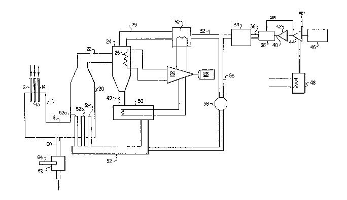
Referring to the drawing, the referenc~ numeral 10
refers, in general, to an entrained 10w gasifier which
receives oxygen, coal and steam from conduits 12, 13, and
~4, respectively. The gasifier is of a conventional
:., ~ . i , . ~ . . . . .
.. ..

2 1 2 3 ~
- 5 - -~
design and therefore will not be described in detail. The
lower, or outlet, end of the gasifier 10 is connected, via
a duct 16, to an entrainment vessel 20 having an inlet
opening in the lowerlportion of one wall thereof which
communicates with the duct. The coal is gasif ied in the
presence of the oxygen and steam in the gasifier 10 in a
conventional manner to produce a syngas which is mixed
with solid ash particles in the vessel. Thus, a mixture
of the syngas and the entrained particles from the -
gasifier 10 are introduced in~o the vessel 20 for reasons
to be described. : ~-~
An outlet is ~ormed at the upp~r portion of the -~
vessel 20 which commu~icates, via a conduit 22, to a
cyclo~e separator 24 which receives the mixture of gases
and particles and operates to separate the gases from the
particles in a conventional manner. A bundle of exchang~
tubes 2~ is providsd in the separa~or 24 and is connected
in a flow circuit including a steam turbine 26 for
circulating water or steam through the bundle to transfer
heat from the gases and particles in the separator ~o ~he
-: . ~ - . .
water or steam for passage to the turbine. The turbin~ 26
is drivingly connected to an electrical generator 28 to
generate electrical power. Since the cyclone separator
.

-`~ 2~23465
24, the tube bundle 25, the turbine 26, and the generator
28 are conventional, they will not be d~escribed in any
further detail.
A gas outlet is provided in the upper portion o~ the
separator 24 and is connected, ~ia a duct 29, to a heat
exchanger 30 which operates in a conventional manner to
transfer heat from the gases received from the duc~ to
water or steam flow circuitry forming a part of the steam ~ .
generation cycle discussed above and thus connected to the
1~ steam turbine 28. The outlet of the heat exchanger 30 is -:~
connected, via a duct 32, to a conventional scrubber 34 to
remove sulfur and other impurities from the gases. A duct
36 connects the scrubber to a combustor 38 which, in turn, ;::~
is connected, via a duct 40, to a gas turbine 42 which
15- drives a compressor 4~ which is in driving engagement with
. .
an elec~rical generator 46. In the combustor 38 the gases
are mi~ed with air from the compressor ~ for eombus~ion
and ~hen expanded thru tha gas turbine 42 to drive the
electrical generator 46 to generate electrical power. A
heat exchanger ~8 is connected to the outlet of ~he gas
turbine 42 and utili~es heat from the gas urbine exhaust
to heat s~eam which is circulated through the ~ .
, , ~ ; , ;- ~ : : ~
: ~: ; . . . . ... . . .. :

21234~3
- 7 - ~ ~ :
above-mentioned flow circuit including ~he steam turbine :~
2~.
The separator 24 includes an outlet for th~ separated
particles which is connected, via a duct 49, to a
fluidized bed heat exchanger 50 which also operates in a -
conventional manner to transfer heat from the separated :
particles to water or steam flow circuitry contained
therein and forming a part of the aforementioned steam
generation cycle including the steam turbine 28. It i5
understood that the tube bundle 26 and the flow circuitry
in the heat exchangers 30 and 50 are shown directly
connected to the steam turbine 26 for the convenience of .
presentation and that this circuitry includes other
components and may involve other co~nections, all of which .~ -
are conventional.
A duct 52 connects the cooled particle outlet of the
heat exchanger 50 to the lower end of the en~rainment
vessel 20. The duct 52 branches into three or more
sligh~ly-spaced vertlcal dis~ributors 52a, 52b, and 52c
which ex~end throu~h the ~o~tom wall of th~ vessel 20 ~ d
i~to the interior of the vessel for introducing the
relatively cool solids into the interior of the vessel 20
for reasons to be des&ribed.

- ~23~
A duct S6 connects the duct 32 to the duct 52 and a ~ m
blower 58 is provided in the duct 56 for utilizing a
portio~ of the gases from the duc~ 32 to transpor~ ~he
relatively cool particles from ~he heat exchanger 50 into :
the vessel 20 and to fluidize the solid~s in the heat
exchanger 50.
A duct 60 extends from the duct 16 for receiving any
relatively large par~icles and passing then to a ~ueIlcher
which receives water from a pipe 64 and cools the
particles be~ore they are passed to a lock hopper, or the
like.
I~ operation, a carbonaceous fuel, such as crushed ;~
coal, is introduced into the gasifier 10 through the
conduct 14 along with a sufficient quantity of oxygen and
steam through the conduct 12 and 13 to achieve ;~
gasification of the coal to generate a syngas, in a
conventional mann~r. The syngas contains some solid
particles bulk ash produced from the coal. This mixture,
at a temperature of approximately 2500~F, which is above
the softening ~emperature of the ash, ~hen passes, via the
duct 16, into the entrainment ve6sel 20 where it is cooled
in a manner to be described, before it is passed, via the
duct 22, to the separator 24.

- 2123~ j
The cooled mixture of syngas and solid particles is
further cooled in the separator 2~ by the heat exchange
with relatively cool water or steam passing through the
tube bundle 25 before the heated water or steam is passed ~ ;
to the steam turbine 26 for driving ~he genera~or 28. The
separator 24 operates to separate the syngas rom ~he
particles, and the former is passed, via the duct 29, to - ~ -~
the heat exchanger 30, and the latter is passed, via the
duct 36, to ~he heat exchanger 50. Heat is transferred
from the syngas in the heat exchanger 30 ~o water or steam ~ ;
passin~ through the flow circuitry associa~ed with ~he
heat exchanger 30 to still further cool the syn~as before
the heated water or steam is passed to the steam turbine
28. The cooled syngas from the heat exchanger 30 is then
passed, via the duct 32, to the scrubber 34 and, then to
combustor 38 where ~he gas is com~usted and expanded ~i
through the gas turbine 42 ~o drive the electrical .
genera~or 46. The exhaust of the gas turbine 42 is passed -~
~o the heat excha~ger 48 for heating steam which is
circulated through the flow circuit including the steam
turbine 26.
The separated particles in the heat exchanger 50 are
fluidized and their heat is transferred ~o water or steam

212346~
~,:
- 10 -
passing through the flow circuitry connecting the heat
exchanger 50 with the steam turhine 26 to still ur~her
cool the particles to a temperature of approximately ~
1000F. The cooled particles are then passed, via the :.
duct 52 and the branch ducts 52a, 52b, a:nd 52c, to the ~ ~
interior of the entrainment vessel 20 where they mix with, ~ ;
and absorb heat from, the mixture of syngas and relatively
hot particles passing therethrough as described above. `~
This heat exchange is sufficient to lower the temperature
of the particles in the syngas-solids mix~ure, to a
temperature of approximately 1600F which is lower than
the softening temperature of the particles. In the above
process of mixing, some agglomeration of ash will occur
and the agglomerated ash will be withdrawn thru duct 60,
quenched in the cooler 62 and passed to external equipment
for disposal. The remaining finer ash at 1600 is thus
rendered non-sticking and will not deposit on any ~:
dcwns~ream heat transfer surfaces. -~
A portion of the syngas is ~apped from the duct 32
and passed, via the duct 56, to ~he duct 52 to
pneumatically assist the movement of the particles from
the heat exchanger 50 to the vessel 20 and to fluidize ~he
particles in the heat exchanger 50. Since ~his syngas is
. . , , ~ , ,, . . .- .

2l2~6oj
at a relatively low temperature by virtue of having passed -~
~hrough the heat exchanger 30, it does not increa~e the
temperature of the particles. ~: :
Therefore, the system and method of the present
invention utilizes a combined gas turbine and steam
turbine cycle while providing an efficient and clean
technique for reducing the temperature of the ash
par~icles to a va}ue be}ow their softening temperature : -
before they are passed through the system.
It is understood that variations may be made in the ~ .
foregoing without departing from the scope of the
invention, For example, an air preheat sys~em can be used
in place of the steam cycle in the heat excha~gers 30
and/or 50 to receive the heat from the gas and the
particles, respectively.
Other modifications, changes and substitutions are
i~tended in the foregoing disclosure and in some instances
some features of the invention will be employed wi~hout a
corresponding use of other features. Accordingly, it is
appropriate that the appended claim~ be construed broadly
and in a manner consisten~ with the scope of the invention. :
'`".

Representative Drawing
A single figure which represents the drawing illustrating the invention.
Administrative Status

2024-08-01:As part of the Next Generation Patents (NGP) transition, the Canadian Patents Database (CPD) now contains a more detailed Event History, which replicates the Event Log of our new back-office solution.

Please note that "Inactive:" events refers to events no longer in use in our new back-office solution.

For a clearer understanding of the status of the application/patent presented on this page, the site Disclaimer , as well as the definitions for Patent , Event History , Maintenance Fee  and Payment History  should be consulted.

Event History

Description Date
Inactive: IPC expired 2018-01-01
Inactive: IPC from MCD 2006-03-11
Time Limit for Reversal Expired 1997-05-12
Application Not Reinstated by Deadline 1997-05-12
Deemed Abandoned - Failure to Respond to Maintenance Fee Notice 1996-05-13
Application Published (Open to Public Inspection) 1995-01-07

Abandonment History

Abandonment Date Reason Reinstatement Date
1996-05-13
Owners on Record

Note: Records showing the ownership history in alphabetical order.

Current Owners on Record
FOSTER WHEELER DEVELOPMENT CORPORATION
Past Owners on Record
ERNEST LUDWIG DAMAN
Past Owners that do not appear in the "Owners on Record" listing will appear in other documentation within the application.
Documents

To view selected files, please enter reCAPTCHA code :


To view images, click a link in the Document Description column. To download the documents, select one or more checkboxes in the first column and then click the "Download Selected in PDF format (Zip Archive)" or the "Download Selected as Single PDF" button.

List of published and non-published patent-specific documents on the CPD .

If you have any difficulty accessing content, you can call the Client Service Centre at 1-866-997-1936 or send them an e-mail at CIPO Client Service Centre.


Document
Description 
Date
(yyyy-mm-dd) 
Number of pages   Size of Image (KB) 
Abstract 1995-01-06 1 35
Claims 1995-01-06 8 375
Drawings 1995-01-06 1 32
Descriptions 1995-01-06 11 591
Representative drawing 1998-02-24 1 14