Note: Descriptions are shown in the official language in which they were submitted.
48663CAN5A
2~2~622
ORTHOPEDIC CASTING MATERIAL AND HERMETIC PACKAGE
_ield of the Invention
~he present invention relates to the field of
orthopedic splinting/casting materials and packaging for
the sameO More particularly, the present invention
relates to curable orthopedic splinting/casting material
in a heat sealed hermetic package which includes means for
facilitating tearing of the package in a predetermined
direction.
Backaround of the Invention
Hermetic packaging constructed from heat
sealable laminated materials is well-known. Many products
are placed in such packages to extend their shelf life by
sealing the products from exposure to air, water vapor,
etc. Heat sealed hermetic packaging constructed from
laminated sheet materials is especially popular because of
its relatively low cost as compared to effectiveness.
The hermeticity of such packages is especially
important in the field of packaging for curable orthopedic
splinting/casting materials. Such products are discussed
in U.S. Patent Nos. 4,433,680; 4,609,578; 4,667,661;
4,774,937; and 5,027,803, all of which are hereby
incorporated for their disclosures relating to those
materials. Briefly, however, such products are extremely
sensitive to ambient levels of water vapor and will harden
(i.e., "cure") upon exposure to very low levels of water
vapor. Once hardened, the product can no longer be used
for its intended purpose and must be discarded. Because
of their sensitivity, such products are typically packaged
,in single-use hermetic packages as constructed from
composite laminate` sheet materials. - ~ -
Hermetically sealed packages constructed from -~ -
laminated sheet materials are~ however, typically
difficult to open due to the nature of the materials used
to manufacture them. ~he laminated sheet materials
typically comprise three or more layers chosen for their
,~ -2- 21~622
strength, mois~ure impermeability, and/or heat
sealability. The composite material is difficult ~o tear
and is particularly difficulty to tear in a desired
direction. As a result, users must typically first tear
the package once and additionally tear, cut or, for
example, open one of the heat sealed ends to provide a
large enough opening to allow adequate access to the
product inside.
One attempt to provide heat sealed hermetic
packages which provide predictable tearing characteristics
is discussed in U.S. Patent No. 4,598,826. Tear strips
are laminated to the interior of the package to facilitate
tearing of the package in a desired direction lying along
the tear strips. Such packages are, however, dif~icult to
lS manufacture as the tear strips must typically be
introduced as the package is formed from the laminated -
sheet material. In addition, the hermeticity of the
packages can be compromised if the tear strips are
included in the heat seals because of their relatively
large profile which is difficult to accommodate in the
heat seals without forming leaks.
Another attempt at addressing the difficulties
in opening such packages includes forming heat sealed
packages with lines of weakness across one of the heat
seals as described in U.S. Patent No. 4,139,643. The
lines of weakness are provided to enhance the
predictability o~ opening the packages. One disadvantage
of this approach is that the package can only be
predictably opened along the heat seals. In many
instances that opening is not large enough to provide
sufficient acress to the product without further tearing
or cutting to enlarge the opening in the package.
Another disadvantage of providing lines of
weakness is the opportunity that they present for leaks -
into the package. Such features may be particularly
vulnerable to flex cracking which can break the thin foil ~ -
vapor barrier layer used in the laminate sheet materials.
~ 3 2:12362,~
Yet another approach to providing predictable
opening characteristics ~or heat sealed hermetic packages
is described in U.S. Patent No. 4,279,344. The packages
discussed in that reference include a heat sealable inner
layer, metal foil vapor barrier layer and outer layer to
protect the metal foil. The heat sealable inner layers
form a peelable bond which is easily separated by the
user. One disadvantage to this approach is that the bond
~ormed is designed to be weak enough to allow for easy
separation which can lead to failure of the package to
maintain its hermetici~y during ~hipping and handling.
European Patent Publication No. ~P 0 471 220
shows a packing pouch. The pouch includPs a resin layer
formed by mel~ extrusion and two parallel strings so that
the pouch can be torn along one of the two strings when a
tear is made between the two strin~s.
Summary of the Invention
Generally, a kit of orthopedic casting/splinting
2~ materials comprises a sheet of curable casting/splinting
material, and a substantially hermetic package containing
the ~heet of curable casting/splinting material. The
package comprises laminate sheet material having an outer
layer and a heat sealable inner layer bonded to the outer
layer, and a heat seal bonding at least a portion of the
inner layer of the laminate sheet material to form the
package. A plurality o~ generally parallel fibers are
substantially evenly spaced apart and disposed between the
inner layer and the outer layer of the laminate sheet
material to guide tearing the package along a
predetermined direction defined by the fibers. The fibers
are substantially evenly spaced along the laminate sheet
material across substantially the entire laminate sheet
material.
The fiber of the tearing means provides a path
along which the laminate sheet material of the package
predictably tears when opened. The path extends along a
. . .
~4~ '~ 2
direction which is sufficiently long to provide easy
access to the product in the package.
The ability to provide predictable opening
properties is especially useful in packaging for
orthopedic splinting/casting materials because such
packages are typically opened at the point of use to limit
the product's exposure to moisture. In addition, easy
acce~s to the product in the package further limits the
time needed to remove ths product and, therefore, the
product's exposure to moisture.
Furthermore, the ability to provide such
properties without compromising the hermeticity of the
package is particularly advantageous.
The preferred laminate sheet material comprises
an inner heat sealable layer laminated to a metal foil
layer which provides the desirable moisture-proof
properties of the laminate. The outer surface of the
metal layer is bonded to an outer layer which preferably
provides toughness and puncture resistance to protect the
vapor barrier properties of the metal foil.
In one aspect o~ the invention, the fibers are
laminated between the metal foil and outer layer. In that
embodiment, the impact of the fibers on the heat seals is
minimized because the fibers are farther from the heat
sealed inner layers.
In another aspect of the invention, the fibers
are laminated between the metal foil and the inner layer.
In that embodiment, the f ibers are better able to tear the
metal foil layer, leading to more predictable tearing
characteristics.
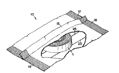
Brief Description of the Drawinqs
FIGURE 1 is a perspective view, partially cut~
away, of one embodiment of a package containing curable
cas*ing/splinting material according to the present
invention.
":
..
~ ~5~ ~12~622
FIGURE 2 is an enlarged partial cross-sectional
view o~ one embodiment of a laminate for use in packages
constructed according to the present invention.
FIGURE 3 is a an alternate embodiment of a
laminate for use in packages constructed according to the
present invention.
FIGURE 4 is a schematic diagram of one process
of manufacturing one embodiment of a laminate for use in
packages according to the present invention.
: :
Detailed Description of the Preferred
and Alternate Emhodiments
Fig. l depicts one embodiment o a pouch
constructed of a laminate sheet material and containing a
roll of curable casting/splinting material according to
the present invention. As shown there, the pouch 10
includes end seals 12 and 14 and a fin seal 16 running
lengthwise along the pouch 10. The pouch 10 also
preferably includes a notch 18 to facilitate opening of
the pouch 10. The pouch 10 is formed of laminate sheet
material 20 which is discussed more fully below.
Located within the pouch is a roll of curable
casting/splinting material 11. The preferred material 11
is moiRture-cura~le and, most preferably, includes an
isocyanate-functional resin which cures when exposed to
moisture. Furthermore, although a roll is depicted in
Fig. 1, it will be understood that t:he material 11 could
be provided as a plurality of rolls or one or more flat
sheets of material. Suitable curable casting/splinting
materials are described in, for example, U.S. Patent Nos.
4,433,680; 4,609,578; 4,667,661; 4,774,937 and 5,027,803;
all of which are incorporated by reference above. Those `
disclosures should not, however, be construed as limiting
the scope of curable materials for packaging according to
the present invention.
Although in the preferred embodiment, pouch 10
comprises two end seals 12 and 14 and a fin seal 1
(commonly referred to as a form, fill and seal pouch), it
'.
r -6- 2 1 2 3 6 ~ 2
will be understood that hermetic heat sealed packages
designed to incorporate laminate sheet material according
to the present invention could take many forms and that
the form described with respect to the preferred
embodiment is only one version of the same. Alter~ate
types of packages could include, but are not limited to,
flat, two-dimensional pouches or three-dimensional, stand-
up gussetted pouches.
Fig. 2 depicts an enlarged cross-sectional view
of a portion of one embodiment of laminate sheet material
used in a preferred embodiment of a package according to
the present invention. The laminate 20 i5 a composite
structure comprising layers 21, 22, 23 and 24. In the
embodiment shown, layer 23 provides a vapor barrisr
through which air and water vapor transmission is severely
limited.
Layers 21 and 22 preferably comprise a
protective layer over the vapor barrier layer 23.
Examples of potential materials for layers 21 and/or 22
include puncture resistant paper or plastic resin
material. It is preferred that one of the outer
protective layers is comprised of at: least one layer of
polyester, nylon or polypropylene which protects the
preferred aluminum foil vapor barrier layer 23 frsm
punctures and tears during shipping and handling.
In one preferred embodiment, outer layer 21
comprises biaxially oriented polypropylene (BOPP) having a
thicXness of 0.001 inch (0.025 millimeter). A layer 22 of
ethylene acetate acrylic (EAA) having a thic~ness of 0.001
inch (0.025 millimeter) is bonded to one side of the layer
21 of BOPP to enhance the bonding of the BOPP outer layer
21 to the vapor barrier layer 2~.
~he EAA layer 22 is bonded to the vapor barrier
layer 23 of aluminum foil (in the preferred em~odiment)
with a thickness of 0.00035 inch (0.00889 millimeter).
Although the preferred vapor barrier layer 23 is
aluminum foil which is entirely free of even minute holes,
it is known that such foils remain highly impervious to
2 ~ 2
air and water vapor transmission even when they include a
few widely scattered minute openings. In other words, by
highly impervious it is meant that as littlP air and water
vapor as possible can pass through the minute openings
found in currently available metal foils used in laminate
sheet material for packaging.
Furthermore, it will be understood that other
materials can be substituted for the preferred aluminum
foil provided they supply the necessary vapor barrier
without significantly affecting the flexibility or
heat/sealability of the laminate 20. Examples of
alternate materials include, but are not limited to,
metallized films, poly-vinylidene chloride coated films
(e.g., SARAN coating), and ACLAR high moisture vapor
permeable films (available from Allied Signal Inc,
Morristown, New Jersey).
Bonded to the inside surface of vapor barrier
layer 23 is an inner layer 24 of heat sealable material
comprising a plastic resin film such as polypropylene,
polyethylene or a polyethylene-polypropylene copolymer
that is extruded an~/or calendared directly onto layer 23.
Most preferably, the heat sealable inner layer 24 is
SURLYN brand resin (#1702) available from E.I. DuPont
deNemours & Company, Wilmington, Delaware. It will,
however, be understood that many other heat sealable
materials could be substituted for the preferred variety.
Examples of alternate materials include, but are not
limited to, other polyethylenes, EAA or any low melting
point thermoplastic material.
Inner layer 24 also preferably provides a
barrier to prevent chemical reactions between the product
in the packages and the ~apor barrier layer 23. It also
provides puncture and abrasion resistance to protect layer
23 from the product contained in any package formed from
the laminate sheet material 20.
In the embodiment illustrated in Fig. 2, fibers
25 are contained within layer 22. The fibers are
preferably spaced on one i~ch (25 mm) centers across the
2 3 6 ~ 2
width of the packaging material. The preferred fiber 25
is a multi-fiber glass filament, although a monofilament
fiber could be substituted. Multiple fiber filaments are
yenerally preferred because their tensile strength is
typically greater (for a given outside diameter) than the
tensile strength of a monofilament fiber. The preferred
fibex has a nominal diameter of 0.00033 inch (0.00838
millimeter/s9 denier). It is constructed of glass fibers
and has a tensile strength of 1.7 lbs. (0.77 kilogram).
The preferred fibers are available from Owens Corning
Fiberglas Company, Toledo, Ohio, under the designation ECD
450 1/0, although other similar fibers, including
monofilament fibers, may be substituted provided their
tensile strength to outside diameter ratio is sufficient
for tearing as described below. In addition to multi- or
mono-filament fibers, it will also be understood that the
fibers can be of many different materials other than
glass. Examples of alternate fiber materials include, but
are not limited to, nylon, polyester, graphite and,
aramid, such as available under the trademarks "KEVLAR" or
"NOMEX" from E.I. DuPont deNemours ~ Company, Wilmington,
Delaware.
The provision of a fiber 25 which has a
relatively small diameter when compared to its tensile
strength is important to operation of the present
invention. The ~ibers 25, when inlaid int~ a laminate
across a web preferably produce a laminate having a very
flat cross-web profile. As a result, the roll is free of
any visible signs of gauge band when the finished laminate
is wound onto a roll. Gauge band is a phenomena which
occurs with extruded laminates when the extrusion
materials are not evenly distributed across the web.
Uneven distribution of the cross web material can cause
di~ficulties when the laminate is wound into finished
roles which can telescope or otherwise be unstable. In
addition, the ~ibers 25 are substantially evenly spaced ~ -
apart across the laminate material 20 which also
9- 21 ~3~2
facilitates even winding o~ the laminate into finished
rolls.
Furthermore, the size of the fibers 25 is
preferably also small to minimize the effect of the fibers
25 in the heat seals 12 and 14 located at the ends of the
preferred embodiment of the pouch 10 depicted in Fig. 1.
Fibers 25 having large diameters could provide the
opportunity for leakage at any heat seals in packages
constructed with laminate sheet material according to the ~ -~
present invention.
When opened, the pouch 10 preferably tears along
one or more of the fibers 25 located within the laminate
sheet material 20 forming the pouch 10. It is
contemplated that one or more of the fibers 25 may break
during the tearing process. In that situation, the tear
line will typically migrate to an adjacent fiber 25 and
continue tearing along the length of the package 10.
Whether the tear in the package follows the initial fiber
25 or whether the tear migrates to another fiber 25, the
pouch 10 will typically be openPd substantially along its
full length, thereby allowing easy access to any product
contained therein.
An alternate embodiment of` a laminate sheet
material 30 according to the present: invention is depicted
in Fig. 3. The laminate sheet material 30 comprises outer
lay~rs 31 and 32 bonded to a vapor barrier-layer 33. As -~
with laminate sheet material 20 in Fig. 2, outer layers 31
and 32 preferably combine to form a protective, puncture-
resistant layer over the vapor barrier layer 33 to prevent
punctures and tears of that layer 33 during handling.
On the opposite side of layer 33 is a heat
sealable layer, preferably of SURLYN brand resin available
from E.I. DuPont deNemours & Company, Wilmington,
Delaware, which is used to heat seal packages formed using
laminate sheet material 30.
In this embodiment, the heat seal layer 34
pre~erably incorporates fibers 35 as opposed to locating
the fibers in the outer layers as described with respect
' , ~ ' I
-' -10- 2~ 23~2
to laminate sheet material 20 in Fiy. 2 above. In all
other aspects, the laminate sheet materi~l 30 of Figure 3
is similar to the laminate sheet material 20 of Figure 2.
In each of the embodiments of laminate sheet
materials 20 & 30 described above, the preferred materials
used to manufacture the products consisted of the
following: the biaxially oriented polypropylene film
(BOPP) is available from Mobil Chemical Corp., Films
Division, Pittsford, NY, under the designation 100 Dicor
LBW. In both embodiments it is provided with a thickness
of 0.001 inches (0.025 mm). The surfaces of the BOPP
material are provided with treatments to increase its
adhesion to materials such as ethylene acetate acrylic
The EAA material is available from ~ow Chemical,
Midland, Michigan, under the designation Primacor 3440 and
is tinted with 5~ (by weight) white Tio2 available from :
Spectrum Color, Minneapolis, MN. The EAA is coated to a
thickness of 0.001 inches (0.025 mm).
The aluminum ~oil is available from Allfoils, -
Inc., Cleveland, OH under the designation type 1145, "Al'
wettability, with a thickness o~ 0.35 mil ~0.00889
millimeter).
The inner heat sealable layer is preferably
5URLYN brand resin, available from DuPont as described
abo~e. It s preferably modified with an anti-block
compound, also available from E.I. DuPont, under the
designation Conpol 5BlOS1.
It will, of course, be understood that many
other materials could be used to form the laminate sheet
materials used in packages according to the present
; invention and that the preferred materials described above
should not be construed as limiting the scope o~ the
invention.
The laminate sheet materials used in packages
constructed according to the present invention are
manufactured in processes similar to those used to .
manu~acture known laminate sheet materials incorporating
~ 2;1~G22
metal foil vapor barriers where no ~ibers are present.
Such manu~acturing techniques are well known to those
skilled in the art of producing packaging laminates and
will not be described in detail herein.
Figure 4 does, however, illustrate a schematic
diagram of one method of manufacturing a laminate sheet
material 50 according to the present invention. As shown
there, the method of manufacturing the embodiment of
laminate sheet material 30 (see Fig. 3) is depicted.
To begin, a sheet of biaxially oriented
polypropylene (BOPP) is extrusion mounted using a layer of
~AA to the preferred barrier material, i.e., aluminum foil
in the preferred embodiment. That composit~ laminate 46
(consisting of BOPP/EAA/foil) is then directed over nip
roll 44 which runs between a chilled textured roll 42,
both of which rotate as depicted. The foil side is
exposed as laminate 46 runs over roll 44. An extrusion
coater 40 deposits a layer of the preferred heat seal
material (SURLYN resin # 1702) into the nip formed between
rolls 42 and 44. Also directed over nip roll 44 are the
fibers 45 according to the present invention.
The process depicted in Fig. 4 results in fibers ~
45 being contained within the heat seal layer of the ;
laminate sheet material 50 produced by this method.
Alt~rnately, it will be understood that fibers
25 depicted in Fig. 2 could be similarly mounted in a
layer o~ ~AA which is extrusion coated onto the vapor
barrier 23 depicted in Fig. 2 D In one preferred process,
the layer 21 o~ biaxially oriented polypropylene (in the
preferred embodiment) is extrusion coated over the layer
of EAA 22 and fibers 25. The heat seal layer 24 of SU~LYN
resin or a similar material can be extrusion coated onto
the vapor barrier 1ayer either before or after the EAA and
~OPP layers have been bonded to the opposing side of the
vapor barrier layer 23.
Although the embodiments described above
incorporate multiple fibers in the laminate sheet
materials, it will also be understood that a single fiber
,. .~ ,,, - , . i , . : ~ :... . .
.
:. .; . . ~ , . .
12- 2123 ~22
could be provided within the laminate sheet material and
that such an embodiment would fall within the scope of the
present invention. In any embodiments incorporating a
single fiber, the tensile strength of the fiber should be
sufficient to resist breaXage during opening of the
package.
Furthermore, although multi-layer laminate sheet
materials with four or more layers are discussed above, it
will also be understood that the use of fibers within two
or three layer laminate sheet materials are contemplated.
In that embodiment, the fiber(s~ would be laminated
between an inner and outer layer of material. Such
laminates (without fibers) are well known and will not be
descrîbed further herein. ~hey are commonly used in
packaging materials such as foods and other products which
do not require the high level of hermeticity needed when
packaging curable casting/splinting materials.
It is to be understood that even though numerous
characteristics and ad~antages of the present invention
have been set forth in the foregoing description, together
with details of one preferred apparatus used to practice
the present invention, the di~closure is illustrative
only, and changes may be made in details, especially in
matters of details which fall within the principles of
the invention to the full extent indicated by the broad,
general meaning of the terms in which the appended claims
are expressed.
,
.
48663-}~.SPC3 ~ ~