Language selection

Search

Patent 2123652 Summary

Third-party information liability

Some of the information on this Web page has been provided by external sources. The Government of Canada is not responsible for the accuracy, reliability or currency of the information supplied by external sources. Users wishing to rely upon this information should consult directly with the source of the information. Content provided by external sources is not subject to official languages, privacy and accessibility requirements.

Claims and Abstract availability

Any discrepancies in the text and image of the Claims and Abstract are due to differing posting times. Text of the Claims and Abstract are posted:

  • At the time the application is open to public inspection;
  • At the time of issue of the patent (grant).
(12) Patent: (11) CA 2123652
(54) English Title: CONTINUOUS BELT PRESS FOR MAKING PANELS
(54) French Title: PRESSE A COURROIES CONTINUES POUR LA FABRICATION DE PANNEAUX
Status: Expired and beyond the Period of Reversal
Bibliographic Data
(51) International Patent Classification (IPC):
  • B27L 11/00 (2006.01)
  • B27N 03/24 (2006.01)
  • B30B 05/06 (2006.01)
(72) Inventors :
  • SIEMPELKAMP, DIETER (Germany)
(73) Owners :
  • SIEMPELKAMP MASCHINEN- UND ANLAGENBAU GMBH & CO. KG
  • G. SIEMPELKAMP GMBH & CO.
(71) Applicants :
  • SIEMPELKAMP MASCHINEN- UND ANLAGENBAU GMBH & CO. KG (Germany)
  • G. SIEMPELKAMP GMBH & CO. (Germany)
(74) Agent: BORDEN LADNER GERVAIS LLP
(74) Associate agent:
(45) Issued: 1998-08-11
(22) Filed Date: 1994-05-16
(41) Open to Public Inspection: 1994-11-19
Examination requested: 1994-10-11
Availability of licence: N/A
Dedicated to the Public: N/A
(25) Language of filing: English

Patent Cooperation Treaty (PCT): No

(30) Application Priority Data:
Application No. Country/Territory Date
P 43 16 555.9-44 (Germany) 1993-05-18

Abstracts

English Abstract


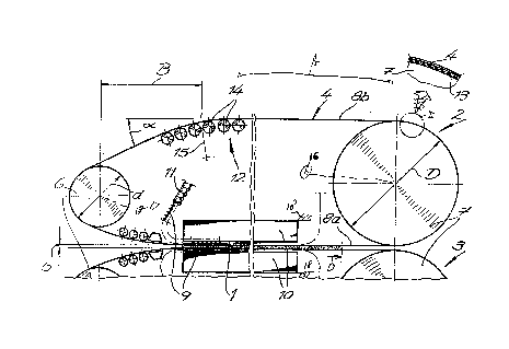
A continuous belt press has a frame having horizontally and
vertically spaced upper and lower plates defining a horizontally extending gap having an
upstream end and a downstream end and vertically spaced upper and lower upstream drums
rotatable on the frame about respective horizontal drum rotation axes at the upstream end.
Vertically spaced upper and lower downstream drums are rotatable on the frame about
respective horizontal drum rotation axes at the downstream end and upper and lower endless
steel belts are spanned over the respective upper and lower drums and each have a working
stretch lying between the plates and a return stretch. Upper and lower sets of rollers are
engaged between the working stretches and the respective plates. The drums are driven to
advance the belts to move the working stretches horizontally in a transport direction to
displace a workpiece in the direction through the gap. The downstream drums have a
diameter which is greater than that allowable by the tension in the respective belts as they
move around the downstream drums and the upstream drums have a diameter which issubstantially less than the diameters of the respective downstream drums and that would not
be usable on the downstream drums because it would exceed the permissible belt tension.
Drives are provided for rotating the downstream drum with a predetermined torque and for
rotating the upstream drum with a torque equal to between 0% and 75% of the predetermined
torque of the downstream drums.


French Abstract

Presse à courroies rotatives comportant un bâti logeant une plaque supérieure et une plaque inférieure espacées horizontalement et verticalement, lesquelles définissent un écartement prolongé dans l'axe horizontal, avec des extrémités amont et aval et un écartement vertical entre des cylindres supérieur et inférieur tournant sur des axes horizontaux respectifs à l'extrémité amont du bâti. Des cylindres supérieur et inférieur tournent sur des axes respectifs à l'extrémité aval du bâti, et des courroies de métal sans fin, l'une supérieure et l'autre inférieure, sont en rotation continue autour de cylindres supérieurs et inférieurs respectifs, chacune recevant une force de travail et une force de retour. Des jeux de rouleaux inférieurs et supérieurs interviennent pour maintenir les forces de travail et de retour. Les cylindres sont entraînés pour faire défiler les courroies qui exercent leur force de travail horizontalement dans la direction du défilement, et produisent le déplacement de la pièce usinée à travers l'écartement. Les cylindres aval ont un diamètre plus grand que ne le permet la tension des courroies respectives qui s'enroulent autour des cylindres aval, et les cylindres amont ont un diamètre qui est significativement moindre que le diamètre des cylindres aval, lequel ne pourrait pas être utilisé sur les cylindres aval en raison de la tension excessive que cela imposerait aux courroies. Des mécanismes d'entraînement produisent le mouvement de rotation du cylindre aval avec un couple prédéterminé, lequel correspond à environ 0 % à 75 % du couple prédéterminé pour les cylindres aval.

Claims

Note: Claims are shown in the official language in which they were submitted.


THE EMBODIMENTS OF THE INVENTION IN WHICH AN EXCLUSIVE PROPERTY
OR PRIVILEGE IS CLAIMED ARE DEFINED AS FOLLOWS:
1. In a continuous belt press having:
a frame having horizontally extending and vertically spaced upper and lower
plates defining a horizontally extending gap having an upstream end and a downstream end;
vertically spaced upper and lower upstream drums rotatable on the frame about
respective horizontal drum rotation axes at the upstream end;
vertically spaced upper and lower downstream drums rotatable on the frame
about respective horizontal drum rotation axes at the downstream end;
upper and lower endless steel belts spanned over the respective upper and lower
drums and each having a working stretch lying between the plates and a return stretch;
upper and lower sets of rollers engaged between the working stretches and the
respective plates; and
drive means connected to the drums for advancing the belts to move the
working stretches horizontally in a transport direction to displace a workpiece in the direction
through the gap;
the improvement wherein
the upstream drums have a diameter which is substantially less than the
diameters of the respective downstream drums;
the working stretches extend horizontally;
deflecting means is provided engaging the return stretches to subdivide same
into a horizontal downstream portion and an upstream portion extending at an angle to the
horizontal;
the downstream drums are provided with friction layers engaging the respective
belts; and
the drive means is provided with the means for rotating the downstream drums
with a predetermined torque and for rotating the upstream drums with a torque equal to
between 0% and 75% of the predetermined torque of the downstream drums; and
the diameters of the downstream drums are equal to
D - d + B ~ lan{x
where:
D = diameter of the downstream drums,
d = diameter of the upstream drums,
B = length of the angled portion of the return stretch, and
.alpha. = angle between the upstream portion of the return stretch
and the horizontal.
2. The press defined in claim 1, further comprising
means for heating the platens and the upstream drums. the upstream drums
directly engaging the respective belts.
-5-

3. The press defined in claim 2 wherein the belts have a width measured
perpendicular to the transport direction which is generally equal to a width of the workpiece
measured perpendicular to the transport direction.
4. The press defined in claim 1, further comprising
means connected to the deflecting means for adjusting the side-to-side position
of the belts.
5. The press defined in claim 4 wherein the deflecting means is an array of
small-diameter rollers.
6. The press defined in claim 1 wherein the belts have a thickness between
l.5mm and 2.5mm.
7. The press defined in claim 1 wherein the belts have a thickness of about
2.3mm.
8. The press defined in claim I wherein the friction layers are such that the
belts do not slip on the downstream drums.
-6-
-- 6 --

Description

Note: Descriptions are shown in the official language in which they were submitted.


~ ~ ~ 3 ~
CONTINUOUS BELT PRESS FOR MAKII~ NELS
SYECT~I(''.~ I'ION t
FIELD Ol l'I-IE INVENTION
The present invention relates to a belt press. More particularly this inventio
concerns a belt press used to make panels, for instance particle board, chip board, plywood,
fiber board, or the like.
BACKGROUND OF THE INVENTION
S ~ standard belt press has a frame having horizontally extending and vertically
spaced upper and lower plates defining a horizontally extending gap having an upstream end
and a downstream end, vertically spaced upper and lower upstream drums rotatable about
respective horizontal axes at the upstream end, vertically spaced upper and lower downstream
drums rotatable about respective horizontal axes at the downstream end, and upper and lower
10 endless belts spanned over the respective upper and lower drums and each having a working
stretch Iying between the plates and a return stretch. Upper and lower sets of rollers engaged
between the working stretches and the respective plates can be recirculated as the belts are
advanced to move with the working stretches horizontally in a transport direction to displace a
workpiece in the direction through the gap so that the working stretches are supported on the
15 respective plates by these rollers.
In standard such systems as described in US patents 4,417,866, 4,613,293, and
5,044,269 the drums are all of generally the same diameter. Both the upstream and
downstream drums, furthermore, are driven with generally the same force so that the working
stretches draw the workpiece along the gap. The effect is that the downstream drums, whicl
20 are responsible for pulling the workpiece through the press, do twice as much work as the
upstream drums. This system works well but requires an expensive drive and relatively
largediameter drums so that neither the upstream or downstream drums are subjected to
excessive stress. In fact the tensions resulting from the drive action and the bending forces
are combined in the drums.

fi 5 ~
OBJECTS O~ TI-II INVENTION
It is therefore an object of the present h1vention to provide an improved
continuous panel-making belt press.
Another object is the provision of such an improv-cl continuous panel-making
5 belt press which overcomes the above-given disadvantages, lha~ is wllicll has an improved
drive system.
SUMMARY Ol~ r'llE INVEN I lO~'
The instal1t hlventiol1 is an in1plovcll1ellt on a COllliln~OLlS bcl~ press havillg a
frame havh1g horizontally extending and vertica~ space~l llppel alUI lowel plates definil1g a
10 horizontally e~tl~n~ing gap having an upstream eod al1cl a dowl1s~le,lll1 cnd and vertically
spaced upper and lower upstream drums rotatablc on thc frame aboul respective horizontal
drum rotation axes at the upstream end. Vertic.lll . spacc~l upper and lower downstream
drums are rotatable on the frame about rcspective holizol1tcll drul1l rotation axes at the
downstream end and upper and lower endless steel belts are spanned over the respective upper
15 and lower drums and each have a working stretch Iying between the plates and a return
stretch. Upper and lower sets of rollers are engaged between the working stretches and the '"~
respective plates. The drums are driven to advance the belts to move the working stretches
horizontally in a t~ansport direction to displace a workpiece in the direction througl1 the ga
According to the invel1tion tl1e downstream drums have a diameter whicl1 is greater tl1al1 ~Im~
20 allowable by the tension in the respective belts as they move around the downstream drums
and the upstream drums have a diameter which is substantially less than the diameters of the
respective downstream drums and that would not be usable on the downstream drums beca-lse
it would exceed the permissible belt tension. The working stretches extend horizontally al1d a
deflecting unit is provided engaging the return stretches to subdivide same into a horizontal
25 downstream portion and an upstream portion extending at an angle to the horizontal so as to
create allowable belt tensions at the upstream drums. Furthermore the downstream drums are
provided with friction layers engaging the respective belts and drives are provided for rotating
the dOwllal~ ll drums with a predet~rmined torque and for rotating the upstream drums with
a torque equal to between 0% and 75% of the predetPrmin~d torque of the duwll,~
3 0 drums.
Continuous belt presses of the above-described generally type are known (see
for example German 2,215,618 filed 30 March 1972 by K. Engels) having upstream drums
that are smaller than the downstream drums. Here however the diameter of the upstream
drums is selected so that it does not exceed the permissible tension in the belt. The
35 downstream drums are of greater diameter than is necessary for the belt tension. The system
of this invention, which controls the driving and provides a friction layer, has a substantially
greater service life than such a prior-art system.
-- 2
'~ A

According to a preferred feature of this invention means is provided for heatil1g
the platens and the upstream drums The upstream drums preferably directly engage tlle
respective belts, that is with no intervening friction layer so there is direct metal-to-metal
contact for best heat transfer. Furthermore the belts preferably have a width measured
5 perpendicular to the transport direction wl1ich is generally equal to a widtl1 of the wor]cpiece
measured perpendicular to the transport direction. In a preferred embodiment, tlle diameters
of the downstream drums are equal to
D = ~ + B ~an(~
where D = diameter of the downstlc.llll clr~ 1s,
d = diametcr of tllc llpstlc,llll clllllus,
B = length of the anglecl poltion of the return stretch, and
o = angle between the upstrc an1 portion of the return stretch
and the horizontal.
In accordance with a further feature of this invention means is provided
15 cormected to the deflector unit for adjusting the side-to-side position of the belts. The
deflector unit can be an array of small-diameter rollers wllicll is r~ivo~al about an axis
perpendicular to the plane of the belt. This type of system is desclibcd in German patent
document 2,803,522 filed 21 January 1978.
The belt according to this invention preferably l~as a ~llickness between 1.5mm
20 and 2.5mm, preferably abo~lt 2.3mm. Tlle ~riction laycrs are s~lcl~ tl~ e belts do not slip on
tlle downstream drums.
BRIEF DESCRIPTION Oi' l'lll DRA~Vll~
The above and other objects, fea~lllc~ ancl ad~al1ta~es will become more rcaclily
apparent from the following description, referellcc being made to the accompanying drawing
25 in which: -
FIG. I is a largely schematic side view of the press according to the invention;and
FIG. 2 is a large-scale view of the detail indicated at II in FIG. 1.
- SPECIFIC DESCRIPTION
As seen in FIG. I a belt press for making a workpiece panel I that may be
particle board, fiber board, plywood, chip board, or the like has substantially identical upper
and lower press parts 2 and 3 mounted on a stationary frame shown schematically at 18 and
together defining a press gap 5 through which the panel I moves in a horizontal transport
direction X. Each press part 2 and 3 has an endless steel belt 4 spanned over a small-
35 diameter upstream drum 6 and a large-diameter downstream drum 7 that subdivide the belts 4
into inner working stretches 8a that define the gap 5 and that move in the direction X and
- A'
........

auter return stretches 8b that move oppositely. Each stretch 8a is supported by rollers 9 on a
respective normally heated press plate 10. The rollers 9 are recirculated by a chain arrange-
ment 11 that is standard in the art.
The drum 7 according to the invention has a diameter D which is substantially
greater than a diameter d of the upstream drum 6. The diameter d is selected such that it
could not be used on the downstream drum 7 because it would not produce sufficient surface
contact to impart sufficient tension to the respective belt 4.
Each outer stretch 8b has a substantially horizontal downstream portion A and
an upstream portion B inclined at an angle a to the hori~ontal. The transition is made over a
curved array 12 of very small-diameter deflecting drums 14 that can pivot about an axis IS
transverse to the belt to allow some lateral adjustment of the belt 4 to prevent it from rum1ing
off to the side.
The drum 7 is driven by a motor 16 and is provided as shown in FIG. 2 with
an elastomeric high-friction layer 13 that substantially eliminates any possibility of slip
IS between the drum 7 and the belt 4. The smaller upstream drum 6 has no such layer and can
idle or be driven by a small-capacity drive 17 that is at least 25% weaker than the drive 16,
and this drum 6 can be heated like the platens 10. The transverse width of the belts 4 is
equal to or slightly more than the width of the workpieccs I so that the belt edges do not get
substantially cooler than the central parts of the belts 4. "
In particular the drum diameters have the following relationship:
D = d + B tana.
The belts 4 have a thickness of between 1.5mm and 2.5mm, here 2.3mm.
A~

Representative Drawing
A single figure which represents the drawing illustrating the invention.
Administrative Status

2024-08-01:As part of the Next Generation Patents (NGP) transition, the Canadian Patents Database (CPD) now contains a more detailed Event History, which replicates the Event Log of our new back-office solution.

Please note that "Inactive:" events refers to events no longer in use in our new back-office solution.

For a clearer understanding of the status of the application/patent presented on this page, the site Disclaimer , as well as the definitions for Patent , Event History , Maintenance Fee  and Payment History  should be consulted.

Event History

Description Date
Inactive: IPC from MCD 2006-03-11
Time Limit for Reversal Expired 2005-05-16
Letter Sent 2004-05-17
Letter Sent 2003-09-11
Grant by Issuance 1998-08-11
Pre-grant 1998-03-05
Inactive: Final fee received 1998-03-05
Notice of Allowance is Issued 1997-11-21
Letter Sent 1997-11-21
Inactive: Application prosecuted on TS as of Log entry date 1997-11-19
Inactive: Status info is complete as of Log entry date 1997-11-19
Inactive: IPC removed 1997-10-08
Inactive: First IPC assigned 1997-10-08
Inactive: IPC assigned 1997-10-08
Inactive: Approved for allowance (AFA) 1997-10-07
Application Published (Open to Public Inspection) 1994-11-19
All Requirements for Examination Determined Compliant 1994-10-11
Request for Examination Requirements Determined Compliant 1994-10-11

Abandonment History

There is no abandonment history.

Maintenance Fee

The last payment was received on 1998-04-20

Note : If the full payment has not been received on or before the date indicated, a further fee may be required which may be one of the following

  • the reinstatement fee;
  • the late payment fee; or
  • additional fee to reverse deemed expiry.

Patent fees are adjusted on the 1st of January every year. The amounts above are the current amounts if received by December 31 of the current year.
Please refer to the CIPO Patent Fees web page to see all current fee amounts.

Fee History

Fee Type Anniversary Year Due Date Paid Date
Final fee - standard 1998-03-05
MF (application, 4th anniv.) - standard 04 1998-05-19 1998-04-20
MF (patent, 5th anniv.) - standard 1999-05-17 1999-04-21
MF (patent, 6th anniv.) - standard 2000-05-16 2000-04-25
MF (patent, 7th anniv.) - standard 2001-05-16 2001-04-25
MF (patent, 8th anniv.) - standard 2002-05-16 2002-04-25
MF (patent, 9th anniv.) - standard 2003-05-16 2003-04-24
Registration of a document 2003-08-12
Owners on Record

Note: Records showing the ownership history in alphabetical order.

Current Owners on Record
SIEMPELKAMP MASCHINEN- UND ANLAGENBAU GMBH & CO. KG
G. SIEMPELKAMP GMBH & CO.
Past Owners on Record
DIETER SIEMPELKAMP
Past Owners that do not appear in the "Owners on Record" listing will appear in other documentation within the application.
Documents

To view selected files, please enter reCAPTCHA code :


To view images, click a link in the Document Description column (Temporarily unavailable). To download the documents, select one or more checkboxes in the first column and then click the "Download Selected in PDF format (Zip Archive)" or the "Download Selected as Single PDF" button.

List of published and non-published patent-specific documents on the CPD .

If you have any difficulty accessing content, you can call the Client Service Centre at 1-866-997-1936 or send them an e-mail at CIPO Client Service Centre.

({010=All Documents, 020=As Filed, 030=As Open to Public Inspection, 040=At Issuance, 050=Examination, 060=Incoming Correspondence, 070=Miscellaneous, 080=Outgoing Correspondence, 090=Payment})


Document
Description 
Date
(yyyy-mm-dd) 
Number of pages   Size of Image (KB) 
Representative drawing 1998-08-04 1 15
Claims 1995-04-13 2 75
Abstract 1995-04-13 1 33
Description 1995-04-13 4 192
Drawings 1995-04-13 1 48
Description 1997-09-14 4 175
Claims 1997-09-14 2 60
Commissioner's Notice - Application Found Allowable 1997-11-20 1 165
Maintenance Fee Notice 2004-07-11 1 172
Correspondence 1998-03-04 1 34
Fees 1997-04-23 1 80
Fees 1996-04-29 1 65
Examiner Requisition 1996-09-26 2 57
Prosecution correspondence 1997-03-25 7 289
Prosecution correspondence 1995-12-18 10 557
Prosecution correspondence 1994-10-10 1 27
Courtesy - Office Letter 1995-01-16 1 61