Note: Descriptions are shown in the official language in which they were submitted.
Wo 93/06368 2 1 2 3 6 8 8 Pcr/US92/08179
DOUBLE ACTING SIMPLEX PLUNGER Pl~MP
BACKGROUND OF THE INVENTION
This invention pertains to hydraulic pumps; the invention provides an
5 improved pump and is generically applicable to double acting simplex plunger pumps
of both broad categories, i.e., "plunger" and "piston" types.
The most relevant prior art known to applicants is U.S. patent 4,978,284
granted 18 December l990; this patent discloses a nurr.ber of unique constructions
and aclvantages over the prior art including that cited therein.
llD The present invention, in turn, provides additional very unique constructions
and several very significant advantages over the prior '284 invention. For example,
the present invention elimin~tes the cr~nkc~ce body 30 and the separate head members
80 of patent '284; the body 30 of '284 is a relatively expensive part because all bores
therein require precision m~rhining. Thus, one advantage of the present invention is
1'5 to have fewer parts and reduced costs of manufacture and greater simplicity.Another very ~ignific~nt advantage of this invention is to use the pump drive
motor end plate or "end bell" as an integral component of the pump; all know prior
art purnps (including the prior '284 arrangement) use some form of adaptor means to
provide a linkage between the e lectric drive motor and the pump apparatus. Thus in
2() patent '284 the cr~nk~ce body 30 was a form of adaptor to provide a linkage and
connection between the motor 107 and the pumping apparatus, i.e. stlJffing boxes 60,
head members 80, manifold 50 and plunger member 96.
Another unique aspect of this invention is a specially shaped pair of unitary
combined stuffing box and head members which, together with a double ended
25 plunger member as a sub~sembly, are sandwiched between the flat or planar axial
end face of the drive motor and a bottom flat or planar surface of a unitary manifold
member.
Another special feature of this invention is an improved precision ~ligning
means and structural holding means for aligning and holding together the individual
3CI component parts of the pump. This unique pump design provides exce11ent and
economical performance and is ~tt~in~ble at an extremely low manufacturing cost in
compa~ison to all known prior ~ut pumps.
SUMMARY OF THE INVENTION
The present invention provides an improved double acting simplex plunger
35 pump c haracterized by having excellent performance and very low manufacturing
costs, the low cost stemming from the unique design which permits the pump to bemade from a very low number of parts. Additionally the pump is very simple to
assemble and to repair.
3 6 8 8
la
The lnventlon provldes double actlng slmplex plunger
pump apparatus adapted to be a.ssembled wlth a rotary motor
havlng a planar axlal end face, an output shaft rotatable
about a shaft axls and extendlng axlally from and
perpendlcular to sald end face, and crank means on the end of
sald shai~t, said pump app.~ratus comprislng: a. flrst and
second unltary comblned stufflng box and head members each
member comprlsing~ a unitary block havlng two spaced apart:
and para:llel surfaces respectlvely deslgnated a motor end face
engaglng surface and a pump manlfold engaglng surface; (11) a
recess in said block for recelvlng a cyllndrlcally shaped
plunger, sald recess havlng a circular cross section and a
longitud:Lnal axls lying parallel to and ln between sald spaceci
apart parallel surfaces; (111) a set of flrst and second pump
port recesses in sald blo,-k and each extendlng from sald pump
manlfold engaging surface lnto sald block and into connective
relationshlp wlth said plunger receiving recess; and (iv)
first and second check valve means respectively and reverse].y
positloned ln sald flrst and second pump port recesses so that:
2() said first check valve mei~ns will admit fluld flow toward sald
plunger recess, and sald second check valve means wlll permlt
fluld flow out of said plunger recess; b. a manlfold havlng a
longitud:Lnal axls, a bottom flat surface adapted to be abutted
by said E)ump manifold engaging surfaces, first and second
transversely spaced apart manlfold lnlet~outlet ports
extendlnq longitudinally lherethrough from a first end to a
second end and mutually parallel to sald longltudlnal axls,
69783-5
,~ "
3 ~
lb
and flrst and second longltudinally spaced apart sets of ports
connectlng sald manifold lnlet:/outlet ports to said bottom
flat surface; c. plunger means comprlslng a shaft havlng a
longltudlnal axls and a preselected longltudlnal length, flrst
and second pumplng means on the ends thereof, and a centrally
located crank engaglng means; and d. means for connectlng sald
members, sald manlfold and sa:Ld plunger to sald planar axlal
end face of sald motor means, whereby: (1) sald members are
preassembled wlth sald plunger means wlth sald flrst and
second pumplng means of sald plunger means being disposed in
said plunger recelving recess; (il) sald members are spaced
apart along said plunger longltudinal axis a preselected
longltudlnal length; (lii) sa:Ld motor end face engaglng
surfaces of sald members are abutting sald planar axlal end
face of sald motor means; ( iV'I said pump manifold engaglng
surfaces of said members are abuttlng said bottom flat surface
of sald manifold; (v) said two sets of flrst and second pump
port recesses of sald members are respectlvely ln reglster
wlth sald flrst and second longltudlnally spaced apart sets of
ports ln sald manifold; and (vi) sa.id crank means is
operatively connected to said crank: engaging means of said
plunger means.
697fl3 5
B
~O 93/06368 2 1 2 3 6 8 8 PCr/USs2/08l79
DESC~IPTION OF THE DRAWINGS
Figure 1 is an isometric view of the assembled pump.
Figure 2 is a view, partly in section, of the pump.
Figure 3 is an end view, partly in section, of the apparatus shown in Figure 2,
5 with a portion of the manifold removed.
Figure 4 is a transverse section of the manifold and one of the combined
stuffing box and head members.
Figures 5 and 6 are bottom and end views respectively of the manifold.
Figures 7, 8 and 9 are views of one of the two identical combined stuffing box
10 and head members, Figure 7 being a view of the side adapted to be in engagement
with the manifold, Figure 8 being a view of the transverse side that includes the
plunger receiving recess, and Figure 9 being a view of the side adapted to the
engagement with the motor face.
Figure 10 is a view of the plunger guide and seal retainer.
Figure 11 is a view on an enlarged scale of one of the two identical chec
valves used in the pump.
Figure 12 is an end view of the motor means.
Figure 13 is a side view of the motor means shown in Figure 12 with only a
portion of the motor depicted.
2() DESCRIPIION OF THE PREFERRED EMBODIMENT
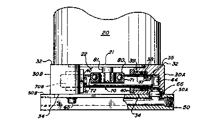
Referring to Figure 1, the reference numeral 10 is used to design~t~ the entire
improved pump. In broad terms the pump comprises a motor means 20, a pair of
combined stuffing box and head members 30A and 30B, a manifold member 50 and a
plunger member 70 (see Figure 2). Figure 1 also shows three mutually orthogonal
25 axes X, Y and Z. The X axis is aligned with, and/or parallel to, the output rotational
axis oi the motor 20. The Y and Z axes are, for example, ~ sentaLti~Je of the
longitudinal axis and one of the transverse axes of the manifold 50. The Y axis is
also parallel to the longitu~in~l or reciprocational axis of the plunger member 70.
Further, the Y and Z axes define a plane which is parallel to several important
30 surfaces of elements of the pump as will be described below.
The combined stuffing box and head members 30A and 30B are identical
subassemblies having identical piece parts and are arranged, as assembled and asshown in Figures 1 and 2, in a reverse or opposite sense as is a~parent from thedrawings. Each of the combined st-lffing box and head members 30A and 30B
35 comprises a unitary block 31, shown most clearly in Figures 7-9, having two spaced
apart and parallel surfaces 32 and 34, shown best in Figures 2 and 8. The flat surface
32 is also designated as a motor end plate eng~ging surface; the flat surface 34 is
designaLted a pump manifold engaging surface. The unitary block 31, as shown most
Wo 93/06368 2 ~ 2 3 6 8 8 PCr/US92/0817g
clearly in Figure 8, has a constant width between the aforedescribed parallel surfaces
32 an~d 34. As clearly shown in Figures 1, 2 and 3 when the members 30A and 30B
are in assembled position, then the parallel surfaces 32 and 34 are also parallel to the
aforernentioned Y-Z plane and the members 30A and 30B are spaced apart from one
another along the longitudinal plunger axis. The other two sides of the block 31, i.e.,
transverse to sides 32 and 34, and as shown in Figures 7 and 9, are defined by the
block having a relatively thick center portion bounded by two generally parallelsurfaces 11 and 12. Surface 11 is relatively short and surface 12 extends from the
ends of surface 11 in the direction of surface 12. The juncture of surfaces 12 and 13
is a rounded connection de~ign~t~d by reference numeral 14. A pair of large
apertures 15 are provided and are shown in Figures 7 and 9.
The block 31 is preferably made from an extrusion of a suitable aluminum
alloy such as 6061 aluminum with each block being a slice from the extrusion with
the flat parallel surfaces 32 and 34 resulting from the slicing process. Thus a basic
extrusion is obtained having the aforementioned external surfaces 11, 12, 13 and 14
as well as the large apellules 15. The "slicing" step will be understood by those
skillecl in the art to include, by way of example, sawing, milling, and grinding.
Each combined stuffing box and head member also includes a deep recess 35
in the block 31 formed by precision boring and extending inwardly from surface 12
(see Figures 7 and 8) for receiving one of the ends 70A and 70B of the cylindr,ically
shaped and reciprocating plunger 70 as shown in Figure 2. The lecesses 35 have acircular cross section with a p~reselected diameter to snugly receive, but not contact,
the ends 70A and 70B of the plunger. When members 30A and 30B are in the
aforesaid assembled position shown in Figures 1-3 the longitudin~l axes of the
recesses 35 of both blocks 31 are in alignment and thus have a common longit~ldin~l
axis lying parallel to the reference axis Y and between the spaced apart parallel
surfaces 32 and 34. The dialmeter and the longitu-lin~l length of the recess 35 are
presel~ted to provide the desired pumping performance.
Each block 31 has an additional plunger guide and sh~ffing recess 37
concentric with the recess 35 and of a larger tli~metPr for receiving a high pressure
seal assembly 38 and a plunger guide or bearing 39. The seal 38 and plunger guide
39 are retainecl in the assembled relationship shown in Figure 2 by a rectangularly
shapecl retainer 40 (see Figw-e 10) having a centrally positioned opening 40' for
accommoclating, but not contacting or restraining, the r~iplo~ling plunger. The
3S retainer 40 is affixed to the b]ock 31 by suitable attachment means such as m~hine
screws 41 (shown in Figures 2 and 3) which pass through apertures 41' or retainer 40
and screw into threaded bores 41 " of block 3 I (see Figure 8).
~VO 93/06368 2 1 2 3 6 8 8 Pcr/US92/08179
Each combined stuffing box and head member 30A and 30B further comprises
a set of first and second purrlp port recesses 43 and 44 which start at the pumpmanifold, eng~ging surface 34 ;md extend preferably perpendicularly into the block 31
a sufficient presele~ted distance so as to be in connective relationship with the plunger
'i receiving recess 35, this being shown clearly in Figures 4 and 7. ~es~s 43 and 44
are shown to have longitudinal axes which are parallel to each other and to the
reference axis X. R~ess~s 43 and 44 further are located symmetrically on opposite
sides of the longitudinal axis of recess 35. Addi ional slightly larger ~ meter
recesses 43A and 44A are provided concentric respectively with recesses 43 and 44
1() adjacent to surface 34 and provide a seat and one half of a combined enclosure for
check valve means to be described below. Also, countersunk or beveled surfaces
43A' ~md 44A' are provided (as shown in Figure 8) adjacent to 43A and 44A
respectively.
Each block 31 has on surface 32 thereof an arcuate shaped recess providing a
lS flat surface 32' which is parallel to the primary surface 32 and with an arcuate surface
22B selected so as to be of the same radius as 22A of shoulder portion 22 of themotor, as shown in Figures 12 and 13.
The manifold 50 is a unitary member having a flat rectangular shape wit a
lon~itu~in~l axis A, shown in Figure S and parallel to reference axis Y. The manifold
20 membe:r 50 has a central relabvely thick portion 51 ~oYtending the full length and a
pair of relabively thin flange portions 52 and 53 extending from opposite sides of
portion 51 as best shown in Figure 6. First and second spaced apart manifold
inlet/olltlet ports 55 and 56 extend longitu~in~lly through the enbire central portion 51
from a first end 51L to a second end 51R (see Figures 1 and 5). The manifold
25; inlet/outlet ports 55 and 56 are mutually parallel to the manifold longitudinal axis
(also reference axis Y) and the ends of the ports 55 and 56 adjacent to ends 51L and
51R are threaded or equivalent as at 55T and 56T to receive a~,opiiate inlet andoutlet piping. In practice, there typically would be one inlet and one outlet; in this
case the two unused ports wou]d be sealed off with standard plugs. Alternately there
3CI could be a double inlet and a double outlet. Additional inlets and outlets may be
provided along and perpendicular to ports 55 and 56.
I,..pol~ntly, the manifold member 50 has a bottom flat surface 50B (Figure 6)
which is adapted to be abutted by said pump manifold eng~ing surfaces 34 of the
combined stuffing box and head members 30A and 30B as is best shown in Figures 2and 4. The manifold 50 is preferably made of the same material as block 31 and is
formed by an extrusion process whereby the longitudinal ports 55 and 56 are integral
with the extrusion, i.e., formed by the extrusion process.
~0 93/06368 2 1 2 3 6 8 8 PCr/US92/08179
Communicating with l:he longitll~in~lly extending ponts 55 and 56 in the
manifold are two sets of transversely extending ponts, the first set being adjacent end
51R and identified by reference numerals 60 and 61 (for coaction with pump port
recesses 43 and 44 of combined stuffing box and head member 30B). The second set~5 of transversely extending manifold ports are adjacent end 51L and are identifierl by
reference numerals 62 and 63. Port set 62/63 is inten~ for coaction with the pump
pont fecesses 43 and 44 of combined stuffing box and head member 30A. Port sets
60/61 and 62/63 are preferably provided by a boring or drilling operation and are
lon~itu(lin~lly spaced apart a presele~t~l distance so that when the manifold is in an
assembled relationship as shown in Figures 1-4, each of said sets of ports 60/61 and
62/63 will be in ~ nment with and in register with a set of pump porlt recesses 43
and 44 in members 30A and 30B respectively.
The sets of manifold transverse ports 60/61 and 62/63 have associated
additional and slightly larger recesses concentric therewith and are identified
1'i respeclively by reference numerals 60A, 61A, 62A and 63A. These additionalrecesses are concentric with ports 60-63 respectively and are of a pres.~lected diameter
and an axial depth (together with r~esses 43A and 44A) to provide a combined
enclosure (see Figure 4) for check valve means identified by reference numerals 66
and 67. Check valve 66 is shown enlarged in Figure 11. Check valves 66 and 67 as2CI indicated are identical and are of standard form and function, i.e. they have a
cylindrical shape with an outer circumferential surface 68 and of a short axial length.
In Figure 11 the directional arrow AA design~tes the direction of fluid flow through
the check valve means upon a pressure dirr.lential being applied across the axial ends
of the c heck valve, as is well understood by those skilled in the art. An O ring 69 is
provided encompassing the outer circumferential surface 68.
As indicated, the check valves 66 and 67 are positioned between the manifold
and members 30A and 30B in opposite senses as is clearly shown in Figure 4. As
shown, check valve 66 will ad~mit fluid flow from manifold port 56 through checkvalve 66 and thence, via 44, into plunger recess 35 while check valve 67 permits fluid
flow of the reverse sense, i.e., from plunger recess through passageway 43, check
valve 67 into manifold port 55.
As indicated above, the manifold recesses 60A, 61A, 62A and 63A in
conjunc:tion with the two sets of recesses 43A and 44A of members 30A and 30B
provide a combined enclosure for the check valve means 66 and 67. Beveled surfaces
60A', 61A', 62A' and 63A' are provided adjacent recesses 60A-63A respectively and
essenti~lly are of the same diameter but of reverse slope of means 43A' and 44A';
thus, thle combined enclosure has a circumferential "V-shaped" recess for receiving
the O ring 69, as shown best in Figures 4 and 11.
~~93/06:368 2 11 ~ 3 ~ ~ ~, Pcr/us9~
The valves 66 and 67 as shown have three very important functions in addition
to the valving function as described above: these functions are (i) providing a
precision alignment means; (ii) providing a structural or holding means for assisting
the holding of the entire assembly together; and (iii) providing an energy absorption
all as described below in more cletail.
The plunger 70 (see Fi,gures 2 and 3) comprises a unitary cylindrical shaft
having a preselected longitudinal length with first and second plunger means on the
ends thereof; it will be understood that (as shown) the actual pumping function is
provided by the snug but noncontacting fit of the plunger shaft into the coacting
plunger receiving recess 35 of the combined stuffing box and head. Thus the ends of
the plunger member, when the same is reciprocated, provide an altemating pumpingaction by displacing fluid in the receiving recess 35, i.e., first at one end (e.g.
member 30A) and then at the other end (e.g. 30B); hence the designator "double
acting." Other plunger or piston configurations may be used with this invention, (e.g.
see the arrangements depicted in Figures 19 and 20 of the aforesaid prior U.S. patent
4,978,2.34).
l'he mid section of the shaR 70 is cut away, as is shown in Figure 2, providing
two shoulder-like surfaces 71 and 72 which are adapted to be engaged by a crank
eccentric or cam means 80 which is connected to the end of a rotatable shaft 81 of the
motor means 20. Cam means ,30 is shown in a "12 o'clock" position in Figure 3.
The variation or extent of the eceentric directly varies the pump displacement.
As shown, motor means 20 is re~res._ntative of electric motors (A.C. and
D.C.) having an output rotatable shaft. However, the invention may be used with
other motors such as hydraulic and pneumatic. The motor means 20 has a planar
axial end face or surface 21 with a central axially extending shoulder portion 2~
having a circumferential surface 22A. The rotational axis of shaft 81 is perpendicular
to the planar end face 21. The combined stuffing box and head members 30A and
30B are spaced apart as shown in Figures 1-3 and preassembled with the plunger
member 70 and such sub-assembly is then clamped between the planar axial end face
21 of the motor 20 and the manifold 50, as shown clearly in Figure 2, by having the
surfaces 32 in abutting engagement with manifold planar surface 50B. During saidassembly, the arcuate surfaces 22B coact with the circumferential surface 22A of the
shoulder 22 of the motor 20. Thus, planar surfaces 32' of 30A and 30B will be
abutting ,against portions of the planar axial end surface 21 and arcuate surfaces 22B
of 30A and 30B will be abutting against portions of the circumferential surface 2A.
M:eans are provided to absorb the energy of the reciprocation of the plunger
70, i.e., (i) the clamping of members 30A and 30B (at arcuate surfaces 22B thereof)
against the arcuate surface 22A o~F the shoulder portion 22 of motor means 20, and (ii)
,~ ,.
'' ;~
~~0 93~06368 2 1 2 3 6 ~ 8 Pcr/usg2/o8l79
the aforedescribed linkage of manifold 50, members 30A and 30B, check valves 66
and 6,7, and the motor means. Further, the check valves 66 and 67, per se, act as
friction or energy absorbers.
As intii~ ted, one category of motor means which may be used as an element
S of the invention is an electric motor of the type commercially available in numerous
sizes and power ratings from several different suppliers; such motors usually have a
shoulder means similar to shoulder 22 and the arcuate surface corresponding to 22A
of such motors are usually held to close low or small tolerances in order to meet
customer requirements. This invention takes advantage of said low tolerance of
1() surface 22A by using this surface as the reference for the pump design, regard being
given to the clamping of arcuate surfaces 22B of members 30A and 30B against
surfacf 22A all as aforesaid.
While the preferred e mbodiment of the invention uses the contact or
engagement of (i) surface 22A with surface 22B and (ii) surface 21 with surface 32,
l'i the scope of the invention includes, if desired, and engagement or contact of surface
22 of the motor means with surface 32' of members 30A and 30B in addition to, or in
place of, the engagement of surfaces 21/32.
The members 30A and 30B thus are key to the unique construction of the
invention. By having them constructed from identical blocks 31 (and with surfaces 32
2CI thereof abutting surface 21 of Ithe motor means) with the axes of lccesses 35 and the
end surfaces 32 and 34 being mutually parallel (and also parallel to the Y-Z plane)
then a first very important criteria is satisfied, i.e., the longitudinal axes of the two
recesses 35 are parallel to the planar surface 21 of the motor means 20.
The next key construction feature is that the members 30A and 30B are
25 oriented with respect to each other so that the aforesaid longi~u(lin~l axes of the
recesses 35 are in precise ~lignment; the result~nt common axis thus defines thereciprocational or longitudina] axis for the plunger 70. The present invention
provides an improved means for aligning the axes of recesses 35 as follows. The
recesses 43/43A and 44144A of the members 30A and 30B and the recesses 60/60A
30 and 62/62A of the manifold aLre bored (or equivalent) using precision procedures.
Upon the insertion of the check valve means into the "combined enclosures" defined
by the said recesses upon assembly of the pump the members 30A and 30B will be
autom~ lly oriented with respect to the reference "X" axis so that the aforesaid~lignmf~nt is achieved. The outer circumferential surface 68 of the check valves is
35 preselected so that the check valves snugly fit within the "combined enclosure" to
assure ~:he desired degree of alignment.
WO 93/06368 2 1 2 3 6 8 8 PCr/US92/08179
Thus the present invention provides an advantageous, effective, and low cost
means for having said longitudinal axis in ~lignmellt, a prerequisite for receiving the
plunger and long term operation of the pump.
As indicated, the shaft 81 rotational axis is perpendicular to end face 21. Thusthe plunger axis is perpendicular to the shaft 81 rotational axis.
The engagement of arcuate surfaces 22B of 30A and 30B with circumferential
surface 22A of the motor means sets or determines the spacing between 30A and 30B
along the plunger axis.
Means are provided to hold members 30A and 30B from moving away from
one another along the plunger axis as a reaction to the force, i.e. reciprocating
energy, of the reciprocating plunger moving into the recesses 35; said means, inbroad terms, includes the m~mifold and, in general, a connection between the
manifold, the members 30A and 30B and the motor means. The specific holding
arrangement depicted is for a ~,efelred embodiment of the invention and includes the
manifold being connected to (i) members 30A and 30B as aforesaid, i.e., the two sets
of check valves 66 and 67 residiing in the combined enclosures, and (ii) the motor end
face by four machine screws 90 having head means abutting the outboard surfaces of
flanges 52 and 53 of the manifold and extending parallel to the reference axis Xthrough apertures 15 of the cornbined stuffing box and head members 30A and 30B
and into a~l~r~,liate threaded recesses 90M in the axial end face 21 of the motor 20.
:[t is to be understood that the embodiment of the invention shown is only for
the purpose of illustration and that the invention is limited solely by the scope of the
appended claims.
We claim: