Note: Descriptions are shown in the official language in which they were submitted.
WO 94/07602 2 1 2 3 7 9 9 PCI /US93/09044
--1--
METHOD FOR CONTROLLING THE
REGENERATION OF A WATER TREATMENT SYSTEM
Back~round of the Invention
The present invention relates to apparatus for softening water; and
particularly to systems for controlling the regeneration of the resin of the water
5 softener.
It is not uncommon for water that is drawn from a well to be considered
"hard" in that it contains di-positive and sometimes tri-positive ions which
have leached from mineral deposits in the earth. Such ions form insoluble
salts with common detergents and soaps producing precipitates that require an
10 increased quantity of detergent or soap for cleaning purposes. When hard water
is used in boilers evaporation results in the precipitation of the insoluble
residues which tend to accumulate as scale.
It is common practice to install a water softener in the plumbing system
of a building that is supplied with hard water. The most common type of water
15 softener is an ion exchange resin-type softener having a tank which holds a bed
of resin through which the hard water is passed to remove undesirable
minerals and other impurities. Initially binding sites in the resin bed containspositive ions, commonly unipositive sodium or potassium ions. As hard water
enters the resin, competition for the binding sites occurs. The di-positive and
20 tri-positive ions in the hard water are favored due to their higher charge
densities and displace the unipositive ions. Two or three unipositive ions are
displaced for each di-positive or tri-positive ion, respectively.
The capacity of the resin bed to absorb minerals and impurities is finite
and eventually ceases to soften the water when a large percentage of the sites
2 5 are occupied by the di-positive and tri-positive ions. When this occurs, it
becomes necessary to recharge or regenerate the resin bed by flushing it with a
regenerant, typically a solution of sodium chloride or potassium chloride. The
wo 94/07602 2 1 2 3 7 ~ ~ -2- Pcr/US93/09044
concentration of unipositive ions in the regenerant is sufficiently high to offset
the unfavorable electrostatic competition and the binding sites are recovered byunipositive ions. The interval of time between regeneration periods during
which water softening takes place is referred to as a "service cycle."
Regeneration of early types of water softeners was affected manually
only after it was discovered that the treatment capacity of the resin bed has
been exceeded and the water flowing therethrough is no longer soft. In an
effort to eliminate the need for manual regeneration, water softener control
systems were developed utilizing a mechanical clock which initiated water
softener regeneration on a periodic basis. The frequency of such regeneration
was set in accordance to the known capacity of the resin bed and the anticipateddaily usage of soft water. While mechanical clock-type water softener
controllers have alleviated the need for manually regenerating the resin bed,
such controllers are subject to the disadvantage that by regenerating at fixed
intervals, regeneration may occur too often or too late depending upon water
usage. Regenerating the water softener resin bed when sufficient capacity to
treat water still exists is wasteful of the regenerant and the water used in
regeneration. Conversely, failure to regenerate the water softener after the
resin bed capacity has diminished to a point below that required to treat hard
2 0 water results in hard water leaving the water softener.
In an effort to better regulate the frequency of water softener resin bed
regeneration, demand-type water softener control units have been developed
which determine the remaining capacity of the water softener resin bed to
soften water. One type of such an improved controller is disclosed in U.S.
2 5 Patent No. 4,426,294 in which a flow meter measures the volume of water be ing
treated and regenerates the resin bed when a specified volume of water has
flowed through the softener since the previous regeneration. While this type
of system is adequate in many installations, municipal systems alternately may
2 1 237~9
draw water from several wells which contain water having
different degrees of hardness. In this case, the exhaustion
of the resin bed is not a direct function of the volume of
water which has been treated since the previous regeneration.
Other types of control systems were developed which
attempted to measure the exhaustion of the resin bed directly.
For example, U.S. Patent No. 4,320,010 placed electrodes in
the resin bed to detect an electrical voltage generated by the
resin bed. This voltage changed when the resin bed became
exhausted, thus providing a mechanism by which the controller
could determine when regeneration was required. Another
control technique measured the conductivity between two pairs
of electrodes placed at different levels in the resin bed.
The difference in conductivity between the two locations in
the resin bed was used to determine when exhaustion of the
water softener had occurred. A system of this type is
disclosed in U.S. Patent No. 4,299,698. A similar technique
is described in U.S. Patent No. 3,618,769 in which the ratio
of the conductivity of two locations ln the resin bed is used
to determine when regeneration should take place.
Summary of the Invention
The present invention provides a water treatment
system comprising: a tank having an inlet and an outlet, and
containing a particle bed; first and second sensors located at
two locations in the particle bed to sense electrical
conductivity at each location; means, connected to said
sensors, for deriving a ratio value representing a ratio of
electrical conductivities sensed at the two locations; a
- 3 -
2 1 23 799
source of first and second predefined threshold values; a
first means for determining whether the ratio value received
from sald means for derivlng ls less than all previous ratio
values produced since a given point in time, to ldentify a
minimum ratio value designated RATIOmin; a flrst means,
responsive to said first means for determining and said means
for deriving, for producing a first probability by dividing
the ratio value by RATIOmin; a first comparator, coupled to
said source and sald first means for producing, to generate an
indication when the flrst probability becomes greater than the
first predefined threshold value; a second means, responsive
to the indication from said first comparator, for determining
whether the ratio value received from said means for deriving
is greater than all previous ratio values occurring after the
indication was generated, to identify a maximum ratio value
designated RATIOmaX; a second means, responsive to said second
means for determining and said means for deriving, for
producing a second probability by dividlng the ratio value by
RATIOmaX; a second comparator, coupled to said source and said
second means for producing, to detect when the second
probability becomes less than the second predefined threshold
value; and a mechanism, coupled to said first and second
comparators, to regenerate the particle bed of the water
treatment system in response to the first probability becoming
greater than the first predefined threshold value followed by
the second probability becoming less than the second
predefined threshold value.
In the preferred embodiment, the conductivity at the
-- 4
,'1-
21 2~799
locations in the resin bed is monitored during regeneration to
determine if a regenerant has entered the tank. If not, a
warning signal is sent to the user.
The present invention also provides a method for
controlling the regeneration of a particle bed in a water
treatment system, steps of which comprise: occaslonally
measuring the conductivity of the particle bed at one location
to produce a first conductivity measurement; occasionally
measuring the conductivity of the particle bed at another
location to produce a second conductivity measurement;
deriving a ratio of the first and second conductivity
measurements; producing a first probability by dividing the
ratio by a minimum ratio value; producing a second probability
of dividing the ratio by a maximum ratio value; and
regenerating the particle bed in response to the first
probability becoming greater than a first predefined threshold
followed by the second probability becoming less than a second
predefined threshold.
Brief Description of the Drawings
FIGURE 1 is a schematic view of a system for
regenerating a water softener according to the present
invention;
FIGURE 2 is a schematic block diagram of the
controller in Figure 1;
FIGURE 3 illustrates a conductivity sensing probe
that is used with the controller in Figure 2;
FIGURE 4 is a state diagram of the operation of the
water softener controller;
k - 4a -
W O 94/07602 2 1 2 3 7 ~ 9 PC~r/~S93/09044
-5-
FIGURE 5 is a flowchart of a routine that is executed by a
microcomputer in the water softener controller to periodically sample the
conductivity at two locations in the softener resin bed; and
FIGURE 6 is a graph of the ratio of electrical current flowing through
two conductivity probes in the resin bed.
Detailed Description of the Invention
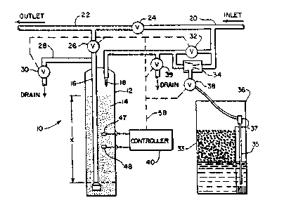
Referring initially to Figure 1, a water softener 10 includes a softening
tank 12 which contains a bed 14 of ion exchange resin particles. An outlet tube
16 extends through the bed 14 from a point adjacent the bottom of the bed. An
inlet pipe 18 extends into the water softener tank 12 and has a discharge
10 opening above the level of the resin bed 14. Hard water is delivered through an
inlet line 20 and treated water is delivered through a service line 22. The inlet
line and the service line are connected through a normally closed valve 24. A
second service valve 26 is interposed between the outlet tube 16 and the serviceline 22. A drain line 28 containing a normally closed first drain valve 30 also
extends from the outlet tube 16.
Hard water can be delivered to the inlet pipe 18 through a service inlet
valve 32. Alternatively, hard water entering the inlet line 20 can pass through
an injector 34 to draw a regenerant solution from a brine tank 36 when a brine
inlet valve 38 is opened and when the service inlet valve 32 is closed. The
2 0 brine tank 36 contains a common salt 33, such as a sodium chloride or
potassium chloride. The withdrawn brine is delivered through line 35 to the
inlet pipe 18 of the softener. The inlet pipe 18 also is connectable to a drain
through a normally closed second drain valve 39.
During service operation, the drain valves 30 and 39, the first service
2 5 valve 24 and the brine inle~ valve 38 are all closed. In this mode of operation,
the second service valve 26 and the service inlet valve 32 are open allowing
W O 94/07602 2 1 2 3 7 9 9 PC~r/US93/09044
-6-
hard water to flow from the inlet line 20 through the inlet pipe 18 onto the topof the resin bed 14. The water passes through the bed 14 and treated water is
withdrawn from the bottom of the bed 14 through outlet tube 16 and into the
service line 22.
The resin bed 14 will eventually become exhausted. In a typical softening
process, this means that the resin bed has changed from a sodium to a calcium/
magnesium condition. A typical regeneration of resin bed 14 commences with
a backwash step. In this step, a control unit 40, that is mechanically connectedto the valves, closes the service inlet valve 32 and the brine inlet valve 38;
while opening the first service valve 24 and the second drain valve 39. Hard
water from the inlet 20 feeds through the outlet tube 16 and upwards through
the resin bed 14 finally exiting through the inlet pipe 18 and the now open
second drain valve 39. Water continues to be supplied to the service line 22 at
this time even though it is not being treated.
The backwash is followed by a brining and rinse. For this operation, the
second service valve 26 and the second drain valve 39 are closed while the
brine inlet valve 38 and the first drain valve 30 are opened. In this state, hard
water is forced through the injector 34 and brine is withdrawn from the tank 36
through a brine line 35. The withdrawn brine is discharged into the softener
2 o tank 12 through inlet pipe 18. The brine passes through the resin bed 14 and
drains through the outlet tube 16 and the now open first drain valve 30. The
concentrated brine solution replaces the di-positive and tri-positive ions in the
resin with unipositive ions recharging the bed. When the contents of the brine
tank 22 have been exhausted, an air check valve 37 closes to prevent air from
2 5 being injected into the system and water will continue to flow through the
injector 34 free of brine. This water propells the brine solution from the tank
and then rinses the bed 14 to remove residual brine. Untreated water will be
21 237~9
supplied to the service line 22 through the open valve 24
durlng thls stage of operation.
During the next stage of operation, the brine tank
36 is refilled and the softener resin bed 14 is purged. This
is accomplished by opening the service inlet valve 32 and the
second service valve 26. Hard water then can enter the brine
tank 36 through the open brine valve 38 and can enter the
tank 12 through the inlet pipe 18. Water passing through the
resin bed 14 exits through the open drain valve 30. The
apparatus is returned to a service condition by closing the
first service valve 24, the first drain valve 30 and the
brine inlet valve 38.
Referring to Figure 2, the controller 40 which
operates the various valves lllustrated in Figure 1 is built
around a microcomputer 42. The microcomputer can comprise
any one of the several commercially available devices, such
as a model MC68HC705P9 manufactured by Motorola, Inc., which
contain internal analog-to-digital converters, random access
memory, read only memory, and clock circuits. An
electrically erasable programmable read only memory (EEPROM)
44 is connected to the microcomputer 42 for the storage and
retrieval of data.
Other outputs of the microcomputer 42 are connected
to a Walsh sine wave summer 46 as described in an article
entitled "Walsh Functlons: A Digital Fourier Series" which
appeared in Byte Magazine September 1977, pages 190-198. The
output of the Walsh sine wave summer 46 is low pass filtered
_ to remove high order harmonics leaving an essentially pure
A -7-
2 1 23 7~9
sine wave at a frequency of approxlmately 1,000 Hz. with an
amplltude of approximately 100 mv-pk. The low excitation
voltage is selected to prevent chemical reduction from
occurring at electrodes in the resin bed. A relatively high
excitation frequency was selected to reduce the effects of
electrode double layer capacitance.
A - 7a -
wO 94/07602 2 1 ~ 3 7 9 ~ Pcr/~ls93/09044
--8--
The output signal from the Walsh sine wave summer 46 is applied to
common electrodes of two conductivity probes, or cells, 47 and 48 located
within the resin bed 14. The lower probe 48 is located at approximately thirty-
eight percent of the effective height (X) of the bed which is the distance between
the uppermost inlet opening at the bottom of outlet tube 16 and the top of the
resin bed. This position was chosen so that the lower conductivity probe 48 willproduce a indication of a conductivity change when approximately twenty
percent of the capacity of the resin bed remains to treat water. It has been
discovered that when the interface between exhausted and unexhausted
sections of the resin bed drops to approximately thirty-eight percent of the
effective height of the resin bed, eighty percent of the resin's capacity to treat
water has been exhausted. This is contrary to intuitive reasoning which would
indicate that the eighty percent depletion point would correspond to a level of
approximately twenty percent of the effective height of the resin bed. The
1 5 upper conductivity probe 47 is positioned in the resin bed approximately six
inches above the lower probe 48.
Referring to Figure 3, each of the conductivity probes 47 and 48 comprises
a pair of electrode rods 61 and 62 embedded in a plastic block 63. Inside the
block, each of the electrodes 61 and 62 connect to two wires 65 and 66 which
2 0 extend to controller 40. The electrodes 61 and 62 are fabricated of gold plated,
stainless steel. The stainless steel of the electrode structure resists corrosion,
while the gold plating makes the surface chemically inert. However, the gold
resists wetting by the water within the tank 12. In order to improve the wetting,
a sleeve 68 of an ion exchange material, such as Nafion (trademark of E.I. du
2 5 Pont de Neumours & Co., Inc.), is bent into a U-shape and inserted over each of
the electrodes. The ends of the U-shaped sleeve are secured to the plastic block63. The sleeve 68 "wets" the hydrophobic gold surface and keeps macro-
molecules away from the electrode surface, thereby further stabilizing it. The
W O 94/07602 2 1 ~ :3 7 9 ~ PC~r/~'S93/09044
_g _
sleeve 68 also protects the relatively soft gold surface from abrasion.
Alternatively, a separate sleeve of ion exchange material can be placed over
each electrode 61 and 62. As a further alternative, another noble metal which isinert to corrosion may be used in place of gold to plate the electrode. In
5 addition, a graphite rod may be used as the electrode and would not require
plating.
Referring once again to Figures 1 and 2, the non-common electrode of
each of the conductivity probes 47 and 48 is connected to a separate current-to-voltage converter 50 and 51, respectively. Each of these converters 50 and 51
10 transforms the magnitude of the current flowing through the associated probe
47 or 48 into a corresponding voltage level. The voltage outputs from the
current to voltage converters 50 and 51 are applied to inputs of the
microcomputer 42 which are connected to internal analog-to-digital (A/D)
converters. As will be described, the microcomputer periodically enables each
15 A/D converter in order to read the magnitude of the voltage produced by the
corresponding current-to-voltage converter.
Another input line to the microcomputer 42 is connected to a service
switch 52 which is closed whenever a regeneration of the water softener 10 is
occurring. A set of indicator lamps 59 are activated by the microcomputer 42
20 as will be described, to provide indications to the user of events such as
depletion of the salt in the brine tank 36 and probe failure. Other types of
signalling devices, such as audible alarms, can be used.
The microcomputer 42 executes a control program which detects the
current flowing through the conductivity probes to determine when the resin
25 bed 14 requires regeneration. Whenever the control program from the
microcomputer 42 determines that regeneration is required, a control signal is
sent via line 54 to a conventional valve control clock and timer 56. This lattercomponent 56 is similar to ones used in previous water softeners which
WO 94/07602 PCr/~iS93/09044
~ 21237~ o-
regenerated the resin bed at a periodic interval and at a time of day (e.g. 2 a.m.)
when water use is minimal. However, the valve control clock and timer 56
will initiate regeneration of the resin bed 14 at that time of day only when a
control signal is being received over line 54. If these conditions are met, the
5 valve control clock and timer 56 rotates a cam shaft 58 which opens and closesthe different valves illustrated in Figure 1 in the sequence previously described
to regenerate the resin bed. The valves and the valve control clock and timer
56 are similar to a valve module manufactured by Autotrol Corporation,
Glendale, Wisconsin under part number 24N and shown in U.S. Patent No.
10 4,426,294.
During operation of the controller 40, its microcomputer 42 is
interrupted periodically by a timed interrupt to execute a conductivity
sampling routine depicted by the flowchart in Figure 5. At the first step 70 of
this routine, the microcomputer 42 sends a digital Fourier term to the Walsh
15 sine wave summer 46. Eight digital Fourier terms are sent for each sine wave
cycle. The Walsh sine wave summer 46 responds by generating an
approximation of a 1,000 Hz. sine wave having an amplitude of 100 millivolts
peak to peak, for example. Because square waves are supplied by the
microcomputer 42 to the sine wave summer 46, only high order odd
2 o harmonics are present in the output which can easily be removed by a low-
pass filter within the summer to give an essentially pure sine wave output.
The output of the sine wave summer 46 is fed through a 100 ohm resistor 49
which is connected in series between the output of the sine wave summer and
the common electrode of the two conductivity probes 47 and 48. The resistor
2 5 49 increases the dynamic range of the conductivity signal because the voltage
applied to the electrodes decreases as the current increases.
The common electrodes of the probes 47 and 48 also are connected to
earth ground to remove any stray currents at the A.C. supply frequency which
W O 94/07602 2 I 2 3 7 ~ ~ PC~r/US93/09044
could otherwise decrease the dynamic range of the sensing and cause false
readings. The signal applied to the cornmon electrode of the two conductivity
probes 47 and 48 is conducted through the sleeve 68 and the resin bed to the
other electrode. The relatively low exciting voltage does not promote
5 chemical reduction of the electrodes and the relatively high frequency reducesthe effect of the double layer capacitance so that the electrodes will appear as a
short circuit. The current which flows through the probes 47 and 48 is directly
proportional to the conductivity of the resin bed and thus can be used as an
indicator of that conductivity. The current-to-voltage converters 50 and 51
10 produce output signals having a voltage level that corresponds to the
magnitude of the current flowing through the associated probe and the output
signals are applied to A/D converter inputs of the microcomputer 42. The
current-to-voltage converters 50 and 51 contain low pass filters to remove
frequencies above the Nyquist frequency for proper digital signal processing.
At step 72 in Figure 5, the microcomputer samples the signal from each
conductivity probe 47 and 48 by digitizing the input signals received from the
current-to-voltage converters 50 and 51 synchronously with the signal
produced by the Walsh sine wave summer 46. The sampling rate is selected to
acquire eight samples of the conductivity probe current during each cycle of the20 1,000 Hz. excitation signal. Since the signal generation and sampling are phase
coherent, the microcomputer 42 tends to reject samples of spurious signals that
were not generated by the Walsh sine wave summer 46. The sampled current
data are multiplied by the sine and cosine of the phase angle of the output
signal from the sumrner 46 at step 74. The resultant sine and cosine terms are
25 summed into registers of the rnicrocomputer 42 for the real (Ireal) and
imaginary (Iimag) current values for the appropriate conductivity probe. A
determination then is made by the microcomputer 42, at step 76, whether
32,000 conductivity samples (4,000 signal cycles) have been summed, during
wo 94/07602 2 1 2 3 7 9 .-~ 12 - Pcr/US93/09044
this service cycle, into the complex Fourier coefficients for the currents from
both probes 47 and 48. If not, the sampling routine terminates until the next
timed interrupt.
The total current (I) of a conductivity probe is given by I = k ~ Ireal2 + Iimag2
5 and is directly proportional to the conductivity of the resin bed at the location of
the probe. The k is a scaling factor representing the gain of the current to
voltage amplifier, an analog to digital scaling factor and the Fourier coefficient
scaling. Once at least 32,000 samples from each conductivity probe 47 and 48
have been acquired, execution of the sampling routine advances to step 78
10 where the ratio of the real and imaginary current sums for each probe is
calculated according to the expression:
I 2 _ Il real + Il imag
R - I 2 + I 2
where Il is the current from the lower probe 47 and I2 is the current from the
upper probe 48, for example. The value ~f IR2 is directly proportional to the
15 square of the ratio of the currents and directly proportional to the square of
the ratio of conductivity of the two conductivity probes. By using the square
of the ratio, the microcomputer 42 does not have to perform the involved
process of calculating the square roots. The resultant current ratio IR2 is
digitally low pass filtered by microcomputer 42 at step 80 to remove relatively
2 0 fast changing factors, such as differential temperature changes across the
probes caused by cold water flowing into a warm resin tank. The filtered ratio
is stored within the microcomputer's memory at step 80.
Then a determination is made whether the value of the new current
ratio IR2 is the largest or the smallest value that has occurred during the present
2 5 service cycle. Specifically at step 82 the value of the new current ratio is
compared to the previous maximum ratio value that is stored in the
microcomputer's memory. When the new current ratio value is greater, it
WO 94/07602 2 I 2 ~ r~ ~ ~3 PCr/US93/09044
-13 -
replaces the previous maximum ratio value in memory at step 84. Then the
value of the new current ratio IR2 is compared to the previous minimum ratio
value at step 86, and replaces that previous value at step 88 if the new currentratio is lower in magnitude.
The ratio of the currents in the two conductivity sensors determines the
state of operation for the water softener controller 40. In order to understand
that operation, reference is made to Figure 6 which shows the ratio of the
currents from the two conductivity probes 47 and 48 throughout a typical water
softener service cycle of several days. Although the conductivity probes have
been designed to minimize their susceptibility to corrosion and chemical
reaction with the minerals in the water, a certain degree of contamination of
the probes occurs over time. As the contamination of the two probes often is
unequal, the ratio of their currents may not be unity even when the
conductivity of the resin bed at the two probe locations is the same. This is
illustrated in the exemplary graph prior to time T1.
Untreated water enters at the top of the softening tank 12 and the ability
of the upper portion of the resin bed 14 to soften the water becomes exhausted
first. As the exhaustion continues, an interface, or front, between the
exhausted and unexhausted resin moves downward through the bed over
time. Eventually at time T1, the exhaustion front moves past the upper
conductivity probe 47. As indicated on the graph in Figure 6, the conductivity
of this probe changes, thereby producing a dramatic increase in the ratio of thecurrents flowing through the two probes 47 and 48. This increase produces a
leading edge in the ratio waveform at approximately time T1. The extent to
2 5 which this ratio increases will vary depending upon a number of factors, such
as the capacity of the resin to attract positive ions, and the values illustrated in
the graph are exemplary only. The exhaustion front continues to move
downward through the resin bed 14, reaching the lower probe 48 at time T2.
W O 94/07602 2 1 2 3 7 9 9 PC~r/US93/09044
-14-
As a result, the conductivity of this probe changes and the ratio IR2 Of the
probe currents decreases. As will be described, it is this decrease in the current
ratio, referred to as the trailing edge of the ratio waveform, which triggers a
regeneration of the resin bed 14. Thus, a short time after T2, the resin bed 14
5 has been recharged and the ratio of the two conductivity probes once again
approaches unity.
The use of the ratio of the currents flowing through the two
conductivity probes 47 and 48 is preferable to prior systems which utilized
merely the difference between the two currents. The ratio minimizes the
10 effects due to a change in the conductivity of water entering the softening tank
12, as may occur when a municipal water system switches between shallow
and deep wells. The ratio method also reduces the effects of temperature
variation on the conductivity measurement by the two probes. If water has
not been required for a period of time, the water in the softener will be
15 relatively warm. Thereafter when a large amount of water is used, colder
water directly from a well may enter the softening tank 12 producing a large
change in the temperature of the conductivity probes. Although such
temperature variations affect the absolute conductivity measurement, their
effects are cancelled by the ratio process. It is well known that the conductivity
2 0 of each probe 47 and 48 also is a function of a "cell constant" which is
determined by the spacing and the length of the cell's electrodes. As these
physical characteristics and degree of contamination vary between conductivity
probes, each conductivity probe 47 and 48 may have a slightly different cell
constant. The effects produced by differing cell constants also are reduced by
25 the present method.
Aside from the interrupt routine which performs the sampling of the
current signals from the conductivity probes 47 and 48, the microcomputer 42
operates as a state machine in performing the control of the water softener
wO 94/07602 2 1 2 3 7 ~ ~ Pcr/US93/09044
-15 -
regeneration. The state machine has six states as illustrated in Figure 4.
Assume that the water softener has been regenerated recently and the
conductivity ratio is close to unity. At this time, the resin bed exhaustion
front has yet to reach the upper conductivity probe 47 and the state machine is
5 in the state 90 waiting for the leading edge of the current ratio pulse which
occurs at time T1.
In order to detect when the leading edge occurs, the microcomputer 42
determines the probability P[le] that a leading edge has occurred using the
following equation:
Present Current Ratio
P[le] 3 (Minimum Ratio Value)
If the value of P[le] is greater than one then the value is set equal to one; and
when P[le] is less than a leading edge threshold (e.g. 0.35), it is set equal to zero.
This leading edge threshold (LET) is depicted by a dotted line in Figure 6.
Alternatively, instead of using the minimum ratio value to determine P~le],
15 an average of the ratios computed since the last resin bed regeneration can be
employed. The use of the ratio average precludes spikes in the current ratio
waveform from significantly affecting the regeneration trip point.
The ratio of the present current ratio IR2 to the minimum ratio value
has been found to be relatively insensitive to differing cell constants of the
2 0 two probes 47 and 48. Conductivity cell constant differences are multiplyingfactors for the current ratios. However, by using a ratio of the probe current
ratios to define the leading edge probability P[le], effects of different
conductivity cell constants are cancelled out of the computation.
Referring once again to the state machine diagram in Figure 4, the
2 5 microcomputer 42 waits at state 90 for the value of the leading edge probability
P[le] to exceed zero as occurs when the leading edge threshold is transcended.
WO 94/07602 2 1 2 3 7 9 9 PCr/US93/09044
-16 -
Until that time, the microcomputer remains in state 90 and uses each new
value of the current ratio IR2 to recalculate P[le].
Once the microcomputer 42 determines that the leading edge probability
P[le] is non-zero, a transition occurs from state 90 to state 91. In this new state,
5 the microcomputer 42 continues to calculate P[le] for a given period of time,
for example one or two hours. If during this period the value of P[le] drops
below the leading edge threshold (P[le]=0), the microcomputer 42 transitions
back to state 90 to once again wait for a leading edge. By waiting at state 91 to
insure that P[le] remains above the leading edge threshold for a period of time,10 spurious short term increases in the current ratio IR2 will not result in
premature regeneration of the softener 10. For example, it has been found that
the exhaustion front often drops in the tank 12 during water usage and then
rises when the flow ceases.
Whenever a transition is made from one state to another,
15 microcomputer 42 stores a designation of the new state in a location within the
EEPROM 44. Should a power failure occur, the non-volatile memory provided
by the EEPROM 44 retains this state designation. Upon restoration of power,
the microcomputer 42 executes a power-up sequence that checks this EEPROM
storage location to determine the state in which to commence operating. This
2 0 process insures that a power outage will not affect the normal cycling of the
water softener control. Thus if a determination that a regeneration should
occur was made prior to the power outage, the regeneration still will take placeupon restoration of power. As will be described, values for other important
variables used in the execution of the control program also are stored in the
2 5 EEPROM 44 for this reason.
When the leading edge probability P[le] remains greater than the leading
edge threshold for the prescribed period of time, the state machine
implemented by microcomputer 42 makes a transition to state 92. Upon this
wO 94/07602 2 1 2 3 7 g 9 PCr/US93/09044
-17 -
transition, the minimum value of the conductivity ratio is stored in the
EEPROM 44. While in state 92, the microcomputer 42 uses each new
value of the current ratio IR2 to calculate the probability of the height of thecurrent ratio pulse P[rh], probability of a trailing edge P[te] and the probability of
5 exhaustion P[ex] as follows:
Maximum Current Ratio
P[rh] 3 (Minimum Current Ratio)
Maximum Current Ratio - Present Current Ratio
P[te] Maximum Current Ratio - Minimum Current Ratio
P[ex] = P[rh] P[te]
If the value of P[rh] is greater than one, it is set equal to one; and when P[rh] is
10 less than a height threshold (e.g. 0.45), it is set equal to zero. The current ratio
pulse height probability P[rh] and the trailing edge probability P[te] both use
the minimum and maximum current ratio values measured since the last
regeneration. Instead of using the maximum ratio value to calculate P[rh] and
P[te], a moving average computed since the last resin bed regeneration can be
15 emplo~ed. The use of a moving average precludes spurious spikes in the
ratio waveform from significantly affecting the regeneration trip point.
It has been found that when the probability of exhaustion P[ex] exceeds
an exhaustion threshold (e.g. 0.38) the hardness front is probably passing the
bottom conductivity probe 48. Because P[ex] is calculated by multiplying P[rh]
20 and P[te], it is apparent that the greater the value of the current ratio pulse
height probability P[rh], the smaller the trailing edge probability P[te] needs to
be to get the value of the exhaustion probability P[ex] above the exhaustion
threshold. This corresponds to the uncertainty of detecting a trailing edge
when there has been a small increase in the ratio. The point where the value
wo 94/07602 2 1 2 3 7 ~ 9 PCr/US93/09044
--18 -
of P[ex] exceeds the exhaustion threshold (ET) is indicated by the dashed line
in Figure 6.
The microcomputer 42 waits at state 92 until the probability of
exhaustion P[ex] exceeds the exhaustion threshold (e.g. P[ex]>0.38). At that
5 time, the state machine in Figure 4 makes a transition to state 93 where the
microcomputer waits to insure that P[ex] remains above the exhaustion
threshold for a specified period of time, for example four hours. State 93
insures that a spurious event does not cause P[ex] to momentarily exceed the
exhaustion threshold and initiate regeneration of the resin bed 14. If the value10 of the probability of exhaustion P[ex] drop below the exhaustion threshold
during this waiting period, a transition occurs back to state 92. When P~ex]
remains above the exhaustion threshold for the specified period of time at step
93, the state machine makes a transition to state 94. Upon this transition, the
present maximum current ratio value is archived in EEPROM 44.
Before making the transition to state 94, the microcomputer 42
calculates the running average of the current ratio pulse height probability
P[rh] for the last four service cycles. The microcomputer compares this
average to the most recent value of P[rh] of the present service cycle. If P[rh] of
the present service cycle is less than a given percentage (e.g. 22.5%) of the
2 0 running average, the microcomputer 42 illuminates a reduced capacity
indicator lamp 59. This lamp provides a visual indication to the user that
either the brine in the brine tank 36 has a low salt concentration, the resin 14has reduced softening capacity, or a fault exists which prevents the full
concentration of brine from entering the softening tank 12. The reduced
2 5 capacity indicator lamp 59 also is illuminated if the probability of a current
ratio pulse height probability P[rh] for the present service cycle is less than
0.55, for example.
wo 94/07602 2 1 2 3 7 9 3 Pcr/US93/09044
-19 -
While in state 94, the microcomputer 42 sends an active signal on line 54
in Figure 2 to the valve control clock and timer 56. This signal indicates that
the resin bed has become exhausted to the point where about twenty percent of
its capacity to soften water remains and regeneration should occur soon.
However, the control valve clock and timer 56 does not immediately initiate
regeneration upon the receipt of an active signal on line 54, but rather waits
until a specified time of day (e.g. 2 a.m.) when minimum water consumption
normally occurs. Waiting until such time of minimum consumption is
desirable as the regeneration process opens the first service valve 24 connecting
10 the hard water inlet line directly to the outlet line, sending untreated hardwater directly to the downstream apparatus which utilize the normally softened
water. The valve control clock and timer 56 may be a conventional mechanical
device, such as that supplied by Autotrol Corporation cited above, which has
been modified for the present system by providing a solenoid that responds to a
15 signal on line 54 by operating a latch which enables an internal clock to initiate
regeneration at the appropriate time of day. Thus regeneration will occur at thedesired time of day after the conductivity measurements indicate near
depletion of the resin bed.
When both of these events occur, the valve control clock and timer 56
2 0 begins rotating the cam shaft 58 which operates the valves 24, 26, 30, 32, 38
and 39 illustrated in Figure 1 through the stages of the regeneration process
described previously. Initiation of the regeneration process by the valve
control clock and timer 56 causes a closure of normally open service switch 52
providing an input signal to the microcomputer 42 indicating that
2 5 regeneration is in progress. The valve control clock and timer 56 also has a
mechanism that is operable by the user to manually initiate the regeneration
cycle. Such manual activation of the valve control clock and timer 56 also
produces a closure of the service switch 52. As manual operation can occur
wo 94/07602 2 1 2 3 7 9 ~ PCrtUS93/09044
-20-
when the microcomputer 42 is in any of the six states shown in Figure 4, a
closure of the service switch 52 forces the microcomputer 42 to make a
transition to step 95 at which it remains while regeneration is in progress.
During the regeneration cycle, while the microcomputer is in state 95, the
5 signals from the two conductivity probes 47 and 48 continue to be sampled by
the interrupt routine depicted in Figure 5. Instead of using the conductivity
ratio while in this state, the microcomputer 42 utilizes the squared total current
from one of the probes as determined at step 82 of the interrupt routine. The
current from either of the two conductivity probes 47 or 48 may be used at this
10 point. After each execution of the sampling interrupt routine, the
microcomputer determines whether the current from the selected probe is the
maximum or minimum value of current occurring during state 95. This is
accomplished by comparing the new current sample to previously stored
minimum and maximum values during the regeneration state 95. If the new
15 value is lower than the current minimum value or greater than the previously
stored maximum value, the appropriate memory location is updated with the
new value. Whenever one of the two values is updated, the microcomputer
calculates the ratio of the maximum value to the minimum value (ImaX/Imin)-
At the onset of the regeneration cycle at state 95, this ratio will be equal or very
2 o close to unity as the conductivity of the resin bed and the water in the tank 12
will not change significantly. However, as the concentrated brine is withdrawn
from tank 36 and enters the softener tank 12, the conductivity within the
softener tank rises dramatically. When the current ratio exceeds a value of 1.9,for example, a flag within the memory of the microcomputer 42 is set to
2 5 indicate that the brine has entered the softener tank.
At the completion of the regeneration cycle, the valve control clock and
timer circuit 56 mechanically opens the service switch 52 providing a signal to
the microcomputer 42 that the regeneration has completed. At this time, the
W O 94/07602 ~ PC~r/US93/09044
-21-
microcomputer checks the flag memory location to determine whether brine
had entered the tank during the regeneration process. If this flag is not set,
which indicates that the conductivity during regeneration did not rise
significantly, the microcomputer 42 sends an active signal to a no salt indicator
5 lamp 59 which provides a visual indication to the user that either the salt 33 in
the brine tank 36 has been used up or that a fault exists which prevents the
brine solution from entering the softener tank 12.
The regeneration process comprises flowing brine from tank 36
through the resin bed 14 for a given interval and then rinsing water through
10 the resin bed for another interval to remove the brine. In the system
described above, these intervals are determined by the valve control clock
and timer 56 in a conventional manner. Alternatively the sensed
conductivity of the resin bed can be used to determine when to terminate the
rinsing. When the brine flows into the resin bed 14, the currents through the
15 conductivity probes 47 and 48 rise dramatically and remain at a high level
until the brine is flushed from the softening tank i2. Therefore, the current
from one of the probes, preferably the lower probe 48, can be sensed during
the rinsing process. When the current from that probe drops below a given
level, rinsing is terminated after a short delay period which insures the brine
2 o has been flushed from the portion of the bed 14 below the probe (e.g. 48)
being used. The latter technique reduces the amount water used to rinse the
softening tank 12 as compared to purely timer based techniques, as well as
returning the softener into service sooner.
When the regeneration process terminates, the microcomputer does
2 5 not immediately make a transition from the regeneration state 95. Even
though the resin bed 14 has been rinsed for a long period of time during the
regeneration process, pockets of concentrated brine may remain within the
resin bed 14, which can adversely affect the conductivity measurements by
W O 94/07602 ~ 3 7 ~ ~ PC~r/US93/09044
-22-
probes 47 and 48. Therefore, the microcomputer 42 remains in the
regeneration state 95 for four or more hours after the service switch 52 has
opened. This delay allows any remaining pockets of brine to be removed by
the normal water flow through the softener tank 12 as well as by distribution
5 within the softener tank. After the microcomputer 42 has waited at state 95
for this period of time after the service switch has opened, a transition is
made to state 90 where the cycle is repeated by the microcomputer waiting
for another leading edge in the conductivity ratio waveform.
During the operation of the water softener controller 40, should the
conductivity ratio fall below 0.78 or exceed 100, a determination is made that
one of the two conductivity probes has failed or become extremely
contaminated. Upon such an occurrence, the microcomputer 42 sends a signal
to one of the indicator lamps in set 59 which provides a visual indication to the
user of this failure. When a probe fails in this manner, regeneration is never
15 initiated based on conductivity as the ratio does not rise and fall. Therefore, an
override is provided so that regeneration occurs periodically (e.g. every fourthday) if the conductivity measurements do not produce regeneration.
The transitioning of the state machine from one state to another has
been described as occurring when certain parameters traverse specified
threshold values. The threshold values given herein are used in the preferred
embodiment of the water softener controller. However, other values for these
thresholds will produce satisfactory operation of the controller without
departing from the inventive concept of the present invention.