Language selection

Search

Patent 2124261 Summary

Third-party information liability

Some of the information on this Web page has been provided by external sources. The Government of Canada is not responsible for the accuracy, reliability or currency of the information supplied by external sources. Users wishing to rely upon this information should consult directly with the source of the information. Content provided by external sources is not subject to official languages, privacy and accessibility requirements.

Claims and Abstract availability

Any discrepancies in the text and image of the Claims and Abstract are due to differing posting times. Text of the Claims and Abstract are posted:

  • At the time the application is open to public inspection;
  • At the time of issue of the patent (grant).
(12) Patent Application: (11) CA 2124261
(54) English Title: UNIVERSAL CUTTER
(54) French Title: COUTEAU TOUT USAGE
Status: Deemed Abandoned and Beyond the Period of Reinstatement - Pending Response to Notice of Disregarded Communication
Bibliographic Data
(51) International Patent Classification (IPC):
  • B26B 7/00 (2006.01)
  • B26B 5/00 (2006.01)
(72) Inventors :
  • MICHEL, WALTER (Switzerland)
(73) Owners :
  • MOHA MODERNE HAUSHALTWAREN AG
(71) Applicants :
  • MOHA MODERNE HAUSHALTWAREN AG (Switzerland)
(74) Agent: KIRBY EADES GALE BAKER
(74) Associate agent:
(45) Issued:
(22) Filed Date: 1994-05-25
(41) Open to Public Inspection: 1994-12-08
Examination requested: 1996-06-24
Availability of licence: N/A
Dedicated to the Public: N/A
(25) Language of filing: English

Patent Cooperation Treaty (PCT): No

(30) Application Priority Data:
Application No. Country/Territory Date
1695/93-6 (Switzerland) 1993-06-07

Abstracts

English Abstract


- 6 -
Abstract
A cutter for vegetables, fruit and the like with, disposed in
front of the cutting knife, an interchangeable, inclined sliding
surface (4) which leads under the knife-edge by the width of the
cutting groove. The housing consists of two parts with a lower
part (16) that is simultaneously adapted as a support and as a
container for the cut produce. The two parts of the housing are
associated with one another by means of a separable hinge (17).


Claims

Note: Claims are shown in the official language in which they were submitted.

- 5 -
Claims
1. A universal cutter for vegetables, fruit and the like having
a sliding surface for guiding the produce to be cut, a knife
disposed in the sliding surface diagonal to the direction of
sliding that separates the sliding surface into two parts, a
cutting groove formed of the knife-edge and the part of the
sliding surface lying lower than the knife, and a housing that
folds out to form a stand, characterised in that the part (4) of
the sliding surface disposed in front of the knife (1) consists
of a part (2) integral with the housing lying in the plane of
the knife and an interchangeable part (4) interposed between
this integral part (2) and the knife (1), and that the sliding
surface of the interchangeable part defines an inclined plane
leading evenly from the integral part (2) to the cutting groove.
2. A universal cutter according to Claim 1, characterised in
that the interchangeable part (4) has the shape of a
parallelogram, the angles of which correspond to the pitch of
the knife (1).
3. A universal cutter according to Claim 1, characterised in
that it has various interchangeable parts (4) with differently
pitched their sliding surfaces which form cutting grooves of
different widths for producing sections of different thickness.
4. A universal cutter according to Claim 1, characterised in
that the interchangeable part has a series of knife-edges (22)
disposed vertical to the sliding surface with which an incision
is made in the produce to be cut before it is cut by the
knife-edge (7) in a direction vertical thereto.
5. A universal cutter according to Claim 1, characterised in
that the housing consists of a cutting part and a support (16)
associated therewith by means of a separable hinge (18) for
supporting the cutter in an inclined position.
6. A universal cutter according to Claim 5, characterised in
that the support is adapted as a container (16) for the cut
produce.

Description

Note: Descriptions are shown in the official language in which they were submitted.


2 1 2
.
~r Universal cutter
.,
The invention relates to a universal cutter for cutting
5 vegetables, fruit and the like having a sliding surface for
guiding the produce be cut, a knife disposed in the sliding
surface diagonal to the direction of sliding that separates the
sliding surface into two parts, a cutting groove formed of the
knife-edge and the part of the sliding surface lying lower than
the knife and a housing that folds out to form a stand.
!~
Cutters for foodstuffs are indispensable kitchen gadgets
since most produce has to be cut into slices, strips, etc. at
some stage in its processing. When different shapes have been
required in the past it has, however, hitherto been necessary to
use several different utensils. It would be desirable to have a
universal gadget with which vegetables, fruit and the like could
~ be processed into cut produce of different shapes and sizes.
1 It is therefore an object of the invention to provide a
universal cutter with which different shapes and sizes of cut
produce can be prepared.
~ ~:
This object is achieved in accordance with the invention by
a universal cutter of the above-described type which is
characterised in that the part of the sliding surface disposed
in front of the knife consists of a part integral with the
housing lying in the plane of the knife and an interchangeable
part interposed between this integral part and the knife, and
that the sliding surface of the interchangeable part defines an
inclined plane leading evenly from the integral part to the
cutting groove.
.~
The sliding surface of the interchangeable part
advantageously has the shape of a parallelogram, the angles of
which correspond to the pitch of the knife.
. .,
s

- -- 2
Different interchangeable parts are preferably also present
with differently pitched sliding surfaces by means of which
cutting grooves of different width are formed to prepare
sections of different thickness.
According to a special embodiment, interchangeable parts are
provided with a series of cutting edges disposed vertically to
the sliding surface with which an incision is made in the
produce to be cut before this is cut by the knife-edge in a
direction vertical thereto.
According to another preferred embodiment, the housing
consists of a main cutting part and a support associated
therewith by means of a separable hinge for setting up the
cutter in an inclined position. The support is preferably
adapted as a container for the cut produce.
An embodiment of the invention will now be described with
reference to the appended drawings. There is shown in
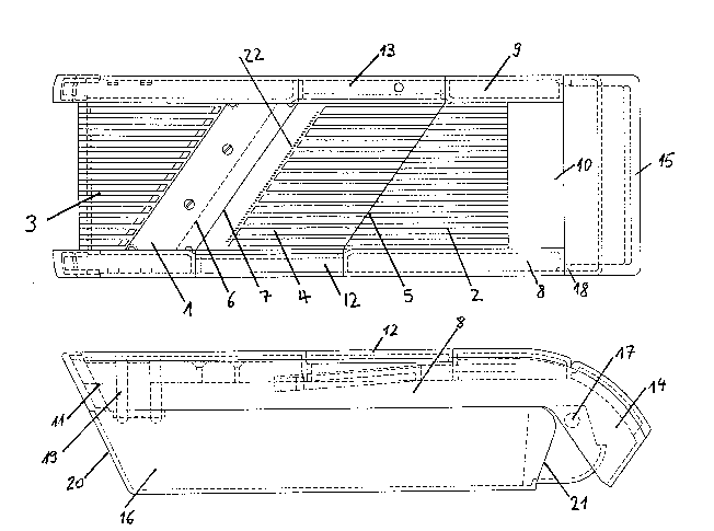
Fig. 1 a plan view of a universal cutter,
Fig. 2 a side view of the same universal cutter,
Fig. 3 a front view of the universal cutter, seen from
the side that can be folded out,
i Fig. 4 a front view of the universal cutter from the side
~ having the hinge,
.~
Fig. 5 a side view of the cutter in the folded out state,
Fig. 6 the hinge of the cutter, in partial section.
.~
As shown in Fig. 1, the cutter has a knife (1) disposed
diagonally in a rectangular, corrugated sliding surface. The
.,1
s
;~
,Atti
~f~

-- 3
corrugated sliding surface consists of three parts: a part
integral with the housing (2) which lies ~,ubstantially in the
plane of the knife (1); a part (3) also integral with the
housing disposed behind the knife; a part (4) forming the shape
of a parallelogram with angles which correspond to the pitch of
the knife. The corrugated surface of the part (4) is diagonally
disposed to the plane of the knife (1) and leads evenly from the
common edge (5) with the part (2) to an edge (6) lying below the
knife. The edge (6) runs parallel to the knife and is disposed
by a distance therebelow which defines the cutting groove
together with the knife-edge (7) of the knife which determines
the thickness of the sections of the produce to be cut.
The entire sliding surface composed of the corrugated parts
(2,3,4) and the knife (1) are disposed in a housing composed of
two lateral pieces (8,9) and transverse connections (10,11) at
the end, the latter laying underneath the cutting surface.
~'
The inserted part (4) also has two lateral pieces (12,13)
which fit into corresponding recesses in the lateral pieces
(8,9) of the frame.
As shown in Fig. 2, the frame has an extension (14)
extending beyond the transverse connection (10) which is bent
downwards. The extension (14) ends in another transverse
connection (15) which forms a handle.
~;
As also shown in Fig. 2, the housing has a lower part (16)
;which is arranged as a trough-shaped container. This lower part
(16) of the housing is associated with the upper part in the
area of the extension (14) by means of a rotating hinge (17).
The rotating hinge (17) consists of a cam (18) shown in Fig. 1
on both sides of the lower part of the housing (16) and
corresponding recesses in the lateral parts of the frame (8 and
9) of the upper part. The cam (18) is also clearly visible in
the partially cut view shown in Fig. 6.
;Two resilient pins (19) disposed in each of the lower parts
of the housing (8 and 9) in the vicinity of the transverse
:
..... . .

connection (11) are provided with step-shaped projections which
mesh with corresponding recesses in the lower part so that the
two parts of the housing cannot become detached from one another
independently.
The lower part of the housing (16) has two functions. In the
closed state that is best seen in Fig. 2, the lower part of the
housing serves to collect cut slices of vegetables, fruit and
the like. It is particularly suitable for this when a smaller
amount of produce has to be cut. The diagonally disposed end
wall (20) of the container is particularly suitable for removing
the cut material.
In its second function, the lower part of the housing serves
as a support for the diagonally positioned universal cutter as
shown in Fig. 5. In this case both parts are folded out until
the upper edge of the extension (14) rests against a shoulder
(21) in the lower part of the housing provided for this purpose.
' The two parts may easily be separated to clean the cutter
and in particular the lower part of the housing. The cam (18) is
! slanted in a wedge shape for this purpose so that the upper part
may be slid off the lower part of the housing in the half-open
! position.
, Differently shaped inserts (4) are provided to prepare
, slices and other shapes of different sizes which may be
, interchanged as required. Different inserts are therefore
provided with differently pitched sliding surfaces and
consequently cutting grooves of different widths. These inserts
make it possible to cut thinner or thicker slices.
Inserts are also provided which have a plurality of cutting
edges (22) disposed vertically to the sliding surface (4) the
height of which correspond to the cutting groove. These cutting
i edges produce parallel incisions in the part of the vegetable,
fruit or the like in such a way that this slice may be separated
into a plurality of strips after a slice has been cut off by the
knife (1).
:,

Representative Drawing
A single figure which represents the drawing illustrating the invention.
Administrative Status

2024-08-01:As part of the Next Generation Patents (NGP) transition, the Canadian Patents Database (CPD) now contains a more detailed Event History, which replicates the Event Log of our new back-office solution.

Please note that "Inactive:" events refers to events no longer in use in our new back-office solution.

For a clearer understanding of the status of the application/patent presented on this page, the site Disclaimer , as well as the definitions for Patent , Event History , Maintenance Fee  and Payment History  should be consulted.

Event History

Description Date
Inactive: IPC from MCD 2006-03-11
Application Not Reinstated by Deadline 2001-03-09
Inactive: Dead - No reply to s.30(2) Rules requisition 2001-03-09
Deemed Abandoned - Failure to Respond to Maintenance Fee Notice 2000-05-25
Inactive: Status info is complete as of Log entry date 2000-05-11
Inactive: Application prosecuted on TS as of Log entry date 2000-05-11
Inactive: Adhoc Request Documented 2000-05-11
Inactive: Abandoned - No reply to s.30(2) Rules requisition 2000-03-09
Inactive: S.30(2) Rules - Examiner requisition 1999-09-09
All Requirements for Examination Determined Compliant 1996-06-24
Request for Examination Requirements Determined Compliant 1996-06-24
Application Published (Open to Public Inspection) 1994-12-08

Abandonment History

Abandonment Date Reason Reinstatement Date
2000-05-25

Maintenance Fee

The last payment was received on 1999-05-13

Note : If the full payment has not been received on or before the date indicated, a further fee may be required which may be one of the following

  • the reinstatement fee;
  • the late payment fee; or
  • additional fee to reverse deemed expiry.

Patent fees are adjusted on the 1st of January every year. The amounts above are the current amounts if received by December 31 of the current year.
Please refer to the CIPO Patent Fees web page to see all current fee amounts.

Fee History

Fee Type Anniversary Year Due Date Paid Date
MF (application, 4th anniv.) - small 04 1998-05-25 1998-05-19
MF (application, 5th anniv.) - small 05 1999-05-25 1999-05-13
Owners on Record

Note: Records showing the ownership history in alphabetical order.

Current Owners on Record
MOHA MODERNE HAUSHALTWAREN AG
Past Owners on Record
WALTER MICHEL
Past Owners that do not appear in the "Owners on Record" listing will appear in other documentation within the application.
Documents

To view selected files, please enter reCAPTCHA code :


To view images, click a link in the Document Description column. To download the documents, select one or more checkboxes in the first column and then click the "Download Selected in PDF format (Zip Archive)" or the "Download Selected as Single PDF" button.

List of published and non-published patent-specific documents on the CPD .

If you have any difficulty accessing content, you can call the Client Service Centre at 1-866-997-1936 or send them an e-mail at CIPO Client Service Centre.


Document
Description 
Date
(yyyy-mm-dd) 
Number of pages   Size of Image (KB) 
Claims 1994-12-07 1 50
Drawings 1994-12-07 3 99
Abstract 1994-12-07 1 18
Descriptions 1994-12-07 4 186
Representative drawing 1998-08-16 1 30
Courtesy - Abandonment Letter (R30(2)) 2000-05-08 1 171
Courtesy - Abandonment Letter (Maintenance Fee) 2000-06-21 1 184
Fees 1996-04-16 1 58
Fees 1997-05-19 1 69
Courtesy - Office Letter 1996-08-22 1 37
Prosecution correspondence 1998-09-29 3 148
Prosecution correspondence 1999-07-12 1 33
Examiner Requisition 1999-07-20 1 34
Prosecution correspondence 1996-06-23 4 195
Examiner Requisition 1998-03-30 3 83
Prosecution correspondence 1999-09-08 2 50