Note: Descriptions are shown in the official language in which they were submitted.
CA 02124533 2004-05-21
LIQUIFIED PETROLEUM GAS FUEL INJECTOR
Field of the Invention
This invention relates to a fuel injector for
injecting liquefied petroleum gas ("LPG") in a fully liquid
state into the intake manifold of an internal combustion
engine.
Background of the Invention
Fuel injectors for injecting gasoline fuel into an
internal combustion engine are well known in the art {see
U.S. Patent No. 4,700,891). Such fuel injectors create
fine atomization of liquid fuel, which improves the
efficiency of the burning cycle.
Prior art gasoline injectors can be classified
into the two categories of "top feed" or "bottom feed"
injectors, describing the location where supply fuel enters
the injector. In both designs, metered fuel exits the
injector through the bottom. Metering is accomplished by a
valve and seat in conjunction with a metering orifice.
Upon energization of a magnetic coil surrounding the valve,
the resulting magnetic force pulls the valve away from the
seat allowing fuel to pass out through the metering
orifice. A spring is typically incorporated to return the
valve to its closed position when the coil is de-energized.
Valve/seat configurations typically employed include a ball
with a mating spherical seat or a valve and seat with
mating conical surfaces. From the metering section, fuel
flows to a spray-generating element which creates a spray
1
pattern of fine droplets of fuel varying from a narrow
stream to cones of different angles.
A solenoid assembly electromagnetically actuates
the fuel metering valve. In the most common configuration,
a coil consisting of a specified number of turns is wound
around a bobbin. The magnetic field produced by the
energized coil generates flux, which travels in a closed
loop around the bobbin. An armature and a pole piece
located just above the armature are positioned within the
coil. The armature is the moving element which controls
fuel flow by opening and closing the valve. The pole piece
is the non-moving element which attracts the armature when
the coil is energized. A fixed gap between the armature
and pole piece prevents contact between them to minimize
residual magnetism effects which would result in delayed
closing of the valve. A non-magnetic stop or spacer is
typically employed to maintain a fixed clearance when the
valve is fully opened.
While fuel injectors for injecting liquid fuel,
such as gasoline or diesel fuel, are common in the art,
little has been done in the art with respect to fuel
injectors for injecting liquified petroleum gas ("LPG")
into an internal combustion engine.
Interest in alternative fuels, such as LPG, has
increased in recent years due to the inherent cost and
environmental advantages over other fuels. LPG has
particularly received much attention as an alternative to
gasoline or diesel fuel for use in internal combustion
engines. Propane, the primary constituent of LPG, :is a
byproduct of the refining of gasoline, and it is a
byproduct of the transfer of natural gases in pipelines.
It is readily available and at costs far below that of
gasoline.
LPG was recently listed under the Clean Air Act in
the United States as a suggested alternative fuel because
2
~~~~~J
it is more envirorunentally compatible than gasoline. LPG
burns more completely, producing less carbon monoxide and
hydrocarbon emissions. Also, using LPG as a fuel reduces
the emission of volatile organic compounds which occurs
during gasoline refueling.
The United States Federal Government recently
promulgated legislation, referred to as Corporate Average
Fuel Efficiency (CAFE) standards, to promote the use of
more environmentally compatible fuels. CAFE created a
system of incentives which encourages manufacturers to
build automobiles and trucks which use alternative fuels,
such as LPG. As a result, there is increased interest in
manufacturing and retrofitting automobiles and trucks to be
fueled with LPG.
Although LPG in its gaseous form has been used as
a reasonably effective fuel in internal combustion engines,
there is an associated reduction in power capability as
compared to liquid LPG fuels. This power reduction is
mainly due to the reduced amount of air and fuel drawn into
the intake manifold when the LPG enters the manifold in
gaseous form.
With liquid LPG, a further gain in peak power (and
simultaneous reduction in the emission of nitrous oxides)
results from the cooling of air and fuel within the
manifold from vaporization of injected LPG. This also
reduces the tendency for engine knock.
Use of LPG in liquid form as a fuel is fairly new
in the art. However, several obstacles are associated with
attempting to inject liquid LPG directly into the intake
r
manifold of an internal combustion engine. zn particular,
it is difficult to maintain LPG in its liquid state near
the heated engine compartment. LPG has a very low boiling
point (see Fig. 5 for the liquid-vapor phase boundaries for
propano and isobutane, the primary constituents of LPG).
Even under pressure, LPG will tend to bubble or boil as the
3
~,~..~~~~~:3
boiling temperature at a given pressure is approached. The
formation of bubbles, often called "champagning" or
"flashing" causes inconsistent injection and poor air~fuel
ratio control.
It is thus necessary to cool the LPG to prevent
this bubbling or boiling. U.S. Patent No. 4,489,700
discloses one approach, where cooling is accomplished by a
spool tip in the injection nozzle which cools.the LPG
within the injector through heat transfer from the
vaporization of injected LPG.
However, the device of U.S. Patent No. 4,4B9,700
and other prior art fuel injectors have in large part been
unsuccessful in maintaining the LPG injected into the
intake manifold in a fully liquid state throughout the
operating range of the engine.
Prior art LPG injectors have another disadvantage.
They lack compatibility with existing gasoline internal
combustion engine configurations. Prior art designs
require significant changes in the power plant itself in
order to convert an engine fueled with gasoline to one
fueled with LPG. ~s a result, retro:Eitting existing
gasoline-powered cars and trucks with a LPG fuel delivery
system has not been a cost effective option.
Prior art LPG injectors are also not compatible
with the existing engine control unit ("ECU") commonly used
in gasoline.wpowered vehicles. The ECU monitors various
engine parameters and controls injection by sending an
electrical current which activates the fuel injector to
cause fuel to be injected into the intake manifold of the
r
engine. Prior art LPG injectors would require a dedicated
system to control LPG injection. Thus, even though some
software modification may be required, a LPG injector which
is compatible with the existing ECU in gasoline-powered
vehicles could further decrease the complexity and cost of
retrofitting a gasoline vehicle with a LPG fuel supply
4
~~.~~~'.~3~
system.
A significant problem encountered when injecting
LPG is that it commonly contains considerable contaminants.
These contaminants or "heavy ends" tend to collect in the
injector over long periods of time. With prior art LPG
injectors, the injector must typically be replaced once
contaminants have callected in the injector in an amount
sufficient to significantly affect the injector's
performance. Thus, a fuel injector designed to allow
removal of such contaminants without requiring replacement
or substantial rebuilding of the injector would result in
substantial cost savings.
Consequently, it is clear that a simple, low cost,
efficient, and effective LPG fuel injector continues to be
needed which accomplishes one or more of the followings
maintains LPG in a fully liquid state during injection; is
compatible for retrofit on vehicles having gasoline
injection systems; allows use of the existing ECU common to
gasoline-injected engines; and permits cleaning of
contaminants without requiring substantial rebuilding of
the injector.
Summary of the Invention
According to the present invention, a fuel
injector for injecting LPG into an internal combustion
engine is provided.
The fuel injector of the present invention
comprises a housing assembly with an inner wall and a
cooling bushing disposed within the housing assembly
against the inner wall. The cooling bushing has a hollow
core and an outer wall with a groove which receives supply
fuel flowing generally from the upper end toward the lower
end of the cooling bushing.
Return fuel, which~is in fluid communication with
the supply fuel, is used to cool the supply fuel as it
5
CA 02124533 2004-05-21
flows through the groove. Return fuel flows through the
hollow core of the cooling bushing generally from the lower
end toward the upper end and exhausts therefrom. Cooling
is accomplished through vaporization of return fuel in the
hollow core. As return fuel is vaporized, heat is absorbed
from the supply fuel to the return fuel through the outer
wall of the cooling bushing, thus cooling the supply fuel
as it flows downward through the groove.
Cooling of the supply fuel prior to injection into
the intake manifold aids in maintaining injected LPG in a
fully liquid state. This allows more fuel and air to enter
the intake manifold prior to the closing of the intake
valve. The result is improved power output, lower toxic
emissions, and a reduction in engine knock.
The present invention is also directed to a fuel
injector for a fuel supply system which injects liquefied
petroleum gas fuel into an internal combustion engine, the
engine having an intake manifold,. said fuel injector
comprising:
a housing assembly having an inner wall;
a cooling bushing disposed Within the housing
assembly, the cooling bushing having upper and lower ends, an
outer wall disposed against the inner-wall of the housing
assembly, and a hollow core, 'the outer wall having a groove
receiving supply fuel flowing generally from the upper end toward
the Lower end; '
means for allowing vaporization of return fuel in
fluid communication with the supply fuel, the -return fuel flowing
through the hollow core generally from the lower end toward the
upper end and exhausting therefrom, thereby cooling the supply
fuel flowing through the groove; and
means for controlling the rate at which fuel is
'-n7ected into the intake manifold in operable connection with
computer means.
6
CA 02124533 2004-05-21
Another object of the invention is to provide a
fuel injector for a fuel supply system which injects
liquefied petroleum gas fuel into an internal combustion
engine, said system having a fuel reservoir and computer
means, said engine having an intake manifold, said fuel
injector comprising;
a housing assembly having a member with a lower
portion, said lower portion defining an axis;
means in fluid communication with said reservoir
for receiving supply fuel from said reservoir and returninq
return fuel to said reservoir;
a valve having a valve plunger and a valve seat;
an electromagnetic coil operably connected to said
computer means, said electromagnetic coil having an internal
region within which for at least a portion thereof magnetic flux
aligns substantially parallel with said axis and runs through,
said lower portion of said member thereby attracting said valve
plunger to said lower portion to open~said valve when said coil
is energized, said lower portion of said housing assembly and
said valve plunger being nearest one another in the internal
region of said coil; and ,
first and second magnetic washers on opposite
sides of said coil directing magnetic flux from said coil
perpendicular to the axis.
Preferably, the fuel injector include an
elastomeric washer between said lower portion of the
housing assembly and said valve plunger preventing contact
between the lower portion and the valve plunger thereby
preventing magnetic historesis in the valve plunger which
may slow operation of the valve plunger.
A still further object of the invention is to
provide a fuel injector for a fuel supply system which
injects liquefied petroleum gas fuel into an internal
6a
CA 02124533 2004-05-21
combustion engine, the engine having an intake manifold,
the injector receiving supply fuel and exhausting non-
injected return fuel, said fuel injector comprising:
a housing assembly having a fuel supply channel and a
fuel return channel, with a portion of the fuel return channel
being adjacent the fuel supply channel, the return fuel in the
return channel flowing countercurrent to the supply.fuel in the
supply channel, the return fuel being in fluid communication with
the supply fuel;
means for vaporizing some of the return fuel, thereby
cooling the supply fuel; and
means for controlling the rate at which fuel is
injected into the intake manifold in operable communication with
computer means.
The invention will be better understood and
further advantages thereof will become more apparent from
the ensuing detailed description of the preferred
embodiments taken in conjunction with the drawings and the
claims annexed thereto.
Brief Description of the Ficrures
Fig. 1 is a cross-sectional front view of a first
preferred embodiment of a fuel injector according to the
present invention, with a fuel rail connected thereto.
Fig. 2 is a cross-sectional side view of the fuel
injector in Fig. 1, with a fuel rail connected thereto,
taken along the line 2-2.of Fig. 1.
Fig. 3 is a cross-sectional front view of a second
preferred embodiment of a fuel injector according to the
present invention, with a fuel rail connected thereto.
Fig. 4 is a cross-sectional side view of the fuel
injector in Fig. 3, with a fuel rail connected thereto,
taken along the line 4-4 of Fig. 3.
Fig. S depicts the-liquid-vapor phase boundaries
for propane and isobutane.
6b
. ~~.~~~ i~iz
Detailed Description of the Preferred Embodiment
Referring now to the drawings, and in particular
to Figs. 1 and 2, a first preferred embodiment of a fuel
injector 10 for injecting liquified petroleum gas ("LPG")
into an intake manifold (not shown) of an internal
combustion engine is shown.
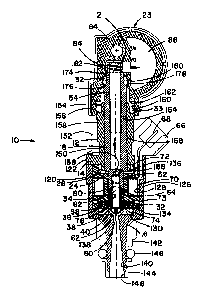
Housing assembly 12 includes cap 14 secured to
outer housing 16 of fuel injector 10. A member in the
preferred form of cooling bushing 18 is secured within cap
14 against annular inner wall 20 of housing assembly 12.
Bushing 18 is held in place by spring 21 located between
fuel rail 23 and upper end 22 of bushing 18. Spring 21
functions to bias shoulder 24 against aligning washer 26.
Referring to Fig. 1, a groove 28 extends vertically in
outer wall 30 of bushing 18.
Outer housing 16 is machined steel which is
cylindrically symmetrical, except for a generally
rectangular flange 120 which mates with a complementary
flange 122 of cap 14. Screws 124, one in each corner of
the mating flanges, hold outer housing 16 and cap 14
together. Screws 124 pass through unthreaded openings in
complementary flange 122 and thread into threaded openings
in rectangular flange 120. Referrinct to Fig. 2 and
proceeding downwardly from flange 120, outer housing 16
includes a larger cylindrical portion 126 with a central
cylindrical cavity 128 for receiving magnet ring 36 and
then bobbin 34. Metering washer 40 is located in a smaller
diameter cavity 130 just beneath cavity 128. Cavity 130 is
i
at sufficient depth to receive metering washer 40 relative
to magnet ring 36 and is sealed by O--ring 74 positioned
between the two. Magnet ring 36 bottoms against the end
132 of cavity 128 when O-ring 74 is appropriately
compressed. A relief groove 134 is formed in the outer,
lower corner of end 1.32 so that ring 36 does not bind up in
7
- ~:~~ ~~~33
the corner before bottoming on end 132. Cavity 128
otherwise has depth sufficient to receive magnet ring 36
arid bobbin 34 such that the top of the upper cylindrical
wall 136 of bobbin 34 reaches the top of rectangular flange
120, but does not contact complementary flange 122. This
clearance is necessary for tolerance reasons to assure
intimate contact between bobbin 34, aligning washer 26, and
bushing shoulder 24, respectively.
extending downwardly from larger cylindrical
portion 126 is smaller cylindrical portion 138. Smaller
portion 138 extends the distance approximately equal to the
longitudinal length of larger portion 126. Smaller portion
138 has a conical passage 140 through which injected fuel
is directed after being ejected from metering orifice 60.
An insulating bushing 142 fits over a little more than half
the length of smaller cylindrical portion 138. Bushing 142
is retained by friction fit. Cap 144 with an O-ring 146
between the opposing end of bushing 142, fits on the end of
smaller diameter portion 138. Cap 144 includes a final
opening 148 through which injected fuel passes. Cap 144 is
also held on smaller cylindrical portion 138 by friction
fit and retains 0-ring 146. With all the elements of the
system, including injectors 10 and fuel rail 23, in proper
position, 0-ring 146 becomes compressed radially between
the mounting bass of the intake manifold (not shown) and
smaller cylindrical portion 138.
Cap 14, as indicated, has a lower flange 122 which
mates with flange 120 of outer housing 16. Cap 14 extends
cylindrically upwardly from flange 122, having a recessed
cylindrical region 150 functioning to retain a molded
plastic member 152 which surrounds cap 14 and on one side
and is further formed as molded plug socket 66. The upper
end of cap 14 has a reduced diameter cylindrical portion
154 ending at shoulder 156 which extends outwardly to the
larger diameter portion 158 of cap 14. The smaller
8
~~.~~~ ~e3~
diameter portion 154, along with shoulder 156 are formed to
receive O-ring 33. The receiving cylindrical cavity 160 in
fuel rail 23 and smaller diameter portion 154 of cap 14 are
formed relative to one another so that O-ring 33 is
appropriately compressed when injector 10 is properly
placed in fuel rail 23. Likewise, shoulder 156 restrains
O-ring 33 at the lower end, while a complementary shoulder
162 in fuel rail 23 provides the same function at the upper
end. Cap 14 has a central cylindrical passage 164 defining
inner wall 20 of housing assembly 12 within which cooling
bushing 18 closely fits. At the lower end of cap 14, a
cylindrical wall 166 extends a short distance beneath
flange 122. The end of wall 166 holds aligning washer 26
snugly against the top of bobbin 34, wherein the aligning
washer 26 tits within upper cylindrical wall 136 of bobbin
34. In this way, O-ring 72 is appropriately compressed to
provide a seal between walls 136 and 166, while being
retained between aligning washer 26 and flange 122.
Cooling bushing 18 extends through cap 14, having
a portion extending above cap 14 and a portion extending
beneath it. The body portion 168 of bushing 18 has a
diameter only slightly smaller than the central cylindrical
passage 164 of cap 14. Body 168 extends downwardly to
aligning washer 26, with which it contacts at a shoulder
24. Lower portion 52 extends downwardly from shoulder 24
through aligrcing washer 26 and about half way into bobbin
34. The upper end of body 168 extends beyond the top of
cap 14, and 'then necks to a smaller diameter portion 174.
O-ring 32 is compressed between smaller diameter portion
174 and a complementary receiving cylindrical cavity 176 in
fuel rail 23. O-ring 32 is retained by a shoulder 178
between body 168 and smaller portion 174 and a
complementary shoulder 180 in fuel rail 23. The top 182 of
bushing 18 is spaced an appropriate distance from a spring
receiving surface 184 of fuel rail 23 to provide for
9
appropriate compression of spring 21 between the two
surfaces. Bushing 18 has hollow core 4B with a restriction
188 in the form of a reduced diameter for a short distance
at approximately the location of the aligning washer 26.
Flow restrictor 46 is retained within the lower portion 52
of hollow core 48 against restriction 188.
Referring now to Fig. 1, supply fuel flows into
fuel injector 10 in the area between first 32 and second 33
O-rings proximate upper end of fuel injector 10. d-ring 32
provides a sealing function between cooling bushing 18 and
fuel rail 23, while O-ring 33 provides a sealing function
between cap 14 and fuel rail 23. Bushing 18 extends
upwardly beyond cap 14 so as to provide intersection of
supply fuel passage 25 in fuel rail 23 with groove 28 in
cooling bushing 18. Supply fuel then flows downward
through groove 28 along body 168 of bushing 18 and through
aligned slots in aligning washer 26, bobbin 34, and magnet
ring 36, progressing to the area between valve 38 and
metering washer 40. Cooling bushing 1B is 3ceyed into
position by corresponding flats (not shown) on aligning
washer 26 and lower portion 52 of bushing 18. Fuel flow
passages 42 in valve 38 allow supply fuel to enter central
chamber 44 within valve 38.
Cooling of supply fuel is accomplished by
employing a flow restrictor 46 to cause vaporisation of
fuel. Flow restrictor 46 causes a pressure drop between
supply fuel in central chamber 44 of valve 38 and return
fuel flowing upward through hollow core 48 of bushing 18.
The preferred pressure drop is approximately 50-60 psi. 3Cn
r
the preferred embodiment, flow restrictor 46 is a porous
metal filter pressed into lower portion 52 of bushing 18.
Such porous metal fitters are commercially available, such
as from Pacific Sintered Metals, 14000 Avalon Blvd., Los
Angeles, CA 90061. Other restrictors, such as a small
orifice or a valve, however, could also be used. A porous
<)')
... . :z,~~.~~a~
metal filter is preferred as a flow restrictor 46 due to
cost considerations and because it provides a more
consistent pressure differential. When supply fuel is at a
sufficiently high temperature, LPG will vaporize as it
passes through flow xestrictor 46. The phase change that
occurs during vaporization causes heat to be absorbed from
supply fuel in groove 28 through outer wall 30 to return
fuel in hollow coxe 48, thus cooling supply fuel as it
passes downward. This internal injector refrigeration aids
in Gaoling LPG to a fully liquid state prior to injection
into the intake manifold of the engine.
Referring now to Fig. 2, outer housing 16 and cap
14 are made of steel for magnetic reasons. Cooling bushing
18 is also made of steel for magnetic reasons and lower
portion 52 of bushing 18 also acts as the pole piece for
-the solenoid. Cooling bushing 18 includes internal threads
54 for mating with an externally threaded removal tool (not
shown) to allow removal of bushing 18. It is desireable to
be able to remove bushing 1B so that accumulated
contaminants, especially near valve 38, can be cleaned from
injector 10. With this design, injector 10 can easily be
cleaned of contaminants without requiring replacement of
the entire injector 10 when contaminants sufficient to
adversely affect the performance of 'the injector 10 have
accumulated. Internal threads 54 also increase the
internal surface area, which results in better heat
transfer.
Valve 38 is biased toward metering washer 40 by
valve spring 58, which extends between the bottom of
central chamber 44 of valve 38 and which is disposed at its
upper end against flow restrictor 46. Valve 38 is
vertically moveable between open and closed positions,
allowing fuel to be injected through fuel flow orifice 60
of metering washer 40 when valve 38 is in the open (i.e.,
"lifted") position.
11
~~~'~~~J~J
Valve 38 is shaped as a ball-ended cylinder,
rather than a pintle or needle-type valve used in
conventional gasoline injectors. The ball shaped valve is
preferred due to its better sealing capability, while spray
pattern development is not a priority. Valve 38 is
comically shaped behind the spherical tip to allow free
flow of fuel to valve seat 62. Spherical tip of valve 38
is preferably dimpled to minimize the contact area of valve
38 with valve seat 62 when valve 38 is in the closed
position. This reduces the force necessary to open valve
3B from its closed position.
The shape of valve 3B and metering washer 40
permit fuel to continue flowing through fuel flow passages
42 of valve 38 when valve 38 is in the closed position.
Thus, at a constant fuel supply pressure, the rate of
supply fuel flowing into central chamber 44 of valve 38 and
through flow restrictor 46 is substantially constant
irrespective of the position of valve 38. Allowing
continuous flow through restrictor 46 throughout the
operating range of injector 10 is critically important to
maintaining supply LPG in a liquid state. This is
especially true during idle when cooling is most needed due
to the longer fuel residence time in fuel rail 23 and
injector 10 associated with the idle condition.
Elastomeric washer 64 is provided between valve 38
and lower portion 52 of cooling bushing 18. Elastomeric
washer 64 is a thin (.008"--.012"), flat, fiber-reinforced
elastamer. The function of elastomeric washer 64 is both
to absorb the shock of valve 38 impacting lower portion 52
i
of bushing 18 and to reduce magnetic historesis. The shock
absorption benefit is a reduction in a major source of
noise in electronic fuel injectors. The magnetic benefit
is faster response time of the valve in response to
activation and deactivatiow of electromagnetic coil 70.
Injector 10 is provided With socket 66 having
12
~:L~~~33
spade connector 68 which is connected to electromagnetic
coil 70 in bobbin 34. Spade connector 68 is compatible
with connectors used with conventional gasoline fuel
injectors. Fuel injection can be controlled with the
existing engine control unit ("ECU") commonly used in
gasoline-powered vehicles. However, changes to the ECU
algorithm may be required to account for variations in
supply LFG temperature and pressure.
A series of O-rings 32, 33, 72, 73, and 74 in
cooperation with spring 21 internally seal injector 10.
First 32 and second 33 0-rings provide sealing at upper end
of injector 10, particularly in the area where supply fuel
enters injector Z0. In addition, first 32 and second 33 O-
rings provide a friction fit with fuel rail 23, causing
sealing between injector 10 and fuel rail 23 and allowing
for easy removal of injector 10 from fuel rail 23. Third
O-ring 72 provides sealing between cap 14 and bobbin 34,
and fourth O-ring 73 provides sealing between bobbin 34 and
magnet ring 36. Spring 21 provides a downward force
against bushing 18 which forces aligning washer 26 against
upper surface of bobbin 34 with shoulder 24 of bushing 18.
Bobbin 34 is forced downward against fourth O-ring 73, thus
sealing the fourth O-ring 73. Magnet ring 36 is forced
downward against fifth O-ring 74 which is sealed between
magnet ring 36 and metering washer 4p.
Valve movement and therefore fuel injection is
controlled electromagnetically by creating a magnetic
reluctance path through activation of electromagnetic coil
70 in bobbin 34 with an electrical current. Cooling
bushing 28 defines a member with lower portion 52 acting as
the pole piece for magnetically attracting valve plunger ?8
of valve 38 acting as the armature. Both pole piece 52 and
armature 78 are positioned within internal region 80 of
electromagnetic coil 7J. Lower portion 52 of bushing 18
defines an axis 82.
13
~~ t~.~~~:3
The reluctance path is as follows. In pole piece
52 of bushing 18, the path is vertically upward and
progresses from bushing 18 to aligning washer 26 acting as
a first magnetic washer. The path continues from aligning
washer 26 to cap 14 and progresses downward through outer
housing 16 and around bobbin 34. The path continues from
outer housing 16 to magnet ring 36 acting as a second
magnetic washer, which directs the magnetic path radially
inward toward valve 38. Metering washer 40 and bobbin 34
are non-magnetic. This reluctance path is possible as a
result of magnet ring 36 and aligning washer 26 in
conjunction with bushing spring 21 and O-rings 72, 73, and
74 which "sandwich" magnet ring 36 and aligning washer 26
to permit the magnetic path around bobbin 34.
This magnetic circuit is created when
electromagnetic coil 70 in bobbin 34 is activated with an
electrical current via spade connector 68. Pole piece 52
of bushing 18 magnetically attracts armature 78, drawing
valve 38 upward to its open position, allowing fuel to pass
through orifice 60 of metering washer 40 and into the
intake manifold of the engine. When the electrical current
is discontinued, valve spring 58 returns valve 38 downward
to its seated and closed position.
In the preferred embodiment, injector 10 is shown
in fluid communication with fuel supply 84 and return 86
channels of fuel rail 23 which provides additional cooling
of supply fuel. However,.injector ZO could be connected to
separate supply and return rails or lines and accomplish
injection of fuel in a fully liquid state, but may require
additional cooling of supply fuel. Both supply 84
and return 86 channels are in fluid communication with a
fuel pressure regulator 88, as shown in Fig. 1. Regulator
88 maintains the fuel pressure in supply channel 84
preferably approximate?y 50-60 psi above the fuel pressure
in return channel 86. Maintaining this fuel pressure
14
~s~~...'.~.>~.)
differential is necessary to drive the refrigeration cycle
within injector 10.
Referring now to Figs. 3 and 4, a second preferred
embodiment of the present invention is shown. In the
second preferred embodiment, the cap 14, cooling bushing
18, and aligning washer 26 of the first preferred
embodiment are replaced with a molded cap 100. The
internal region of molded cap 100 provides the same
function as cooling bushing l8, having a hollow core 102
defining a return channel and a lower portion 52 acting as
a pole piece. Two fuel supply channels 106 molded .into cap
100 on opposite sides of hollow core 102 extend to
corresponding slots in bobbin 108 and magnetic ring 110.
Forming supply 106 and return 102 channels in molded cap
100 as a single member can result in substantial cost
savings in manufacturing injector 112.
It should be understood that the present invention
is not limited to the preferred embodiments discussed
above, which are illustrative only. Changes may be made in
detail, especially in matters of shape, size, arrangement
of parts, and material of components within the principles
of the invention, to the full extent indicated by the broad
general meanings of the terms in which the appended claims
are expressed.
15