Note: Descriptions are shown in the official language in which they were submitted.
~ ~4778
Docket No. 1469-IR-PA
A SCREENING DEVICE FOR A FIBER SLURRY, AND
A BACKWASH MEANS THEREFOR
BACXGROUND OF THE INVENTION
This invention pertains, generally, to devices for
screening fluid suspensions, such as screens and
separators, and the like, and in particular to screening
devices used in processing wood pulp slurries in
papermaking processes, and to novel backwash means
therefor.
Screenplates, or screens of such devices tend to
clog with suspended fiber and, as a consequence thereof,
means are required for cleaning the screens of the
clogging fibers. Typically, hydrofoils are used to
generate a backwash wave or surge to effect the necessary
cleaning. In this, of course, there must be relative
motion between the screen and the hydrofoil. The
hydrofoil is arranged in proximate adjacency to the
screen surface, whether the screen is cylindrical, disc
or planar-shaped, or frustoconical.
The hydrofoils used for the aforesaid purpose may
take many forms, including airfoil sections, radial
vanes, and drum-mounted devices such as blades, bumps and
half-foils. They are characterized by the generation of
Docket No. 1469-IR-PA
two, successive pressure pulses, in the slurry, the first
pulse having a pressure greater than the ambient
pressure, and the second having a pressure lower than the
ambient.
Known apparatuses and devices which employ
hydrofoils are characterized by high relative velocity
between the screenplate or screen and the hydrofoil, and
a backwash flow surge which is limited by various
factors, in particular: by cavitation during the negative
pressure pulse, and by a high, positive pulse resulting
in an accept flow surge which tends to reduce separation
efficiency.
The foregoing illustrates limitations known to exist
in present screening devices. Thus, it is apparent that
it would be advantageous to provide an alternative
directed to overcoming one or more of the limitations set
forth above. Accordingly, a suitable alternative is
provided including features more fully disclosed
hereinafter.
SUMMARY OF THE INVENTION
In one aspect of the invention, this is accomplished
by providing a screening device for a fiber slurry,
~12~778
Docket No . 14 69-IR-PA
comprising a screen for screening fiber slurry; a
backwash generator, mounted in adjacency to the screen,
for causing slurry to backwash through the screen; and
means for causing relative movement between the screen :
and backwash generator, wherein the screen has first and
second, opposite surfaces; and the backwash generator
comprises means disposed adjacent to the opposite
surfaces for causing slurry to surge through the screen
from the first surface to the second surface, and from
the second surface to the first surface. :
Another aspect of the invention meets the aforesaid
purpose by setting forth a backwash means, for a
screening device for a fiber slurry, comprising a
hydrofoil for mounting thereof in proximate adjacency to
a fiber slurry screen of a screening device; wherein the
hydrofoil has means formed thereon defining a barrier to
slurry flow therealong, and for causing slurry to flow
away from the hydrofoil, in a direction substantially
normal to the hydrofoil.
The aforesaid and other aspects of the invention,
will become apparent by reference to the following
description of embodiments of the invention, when
considered in conjunction with the accompanying drawing
figures.
. . - ~
CA 02124778 1998-08-2~
BRIEF DESCRIPTION OF THE DRAWING FIGURES
Figure 1 is a partially-sectioned, elevational
view of an apparatus, namely a screening device for a
fiber slurry, incorporating an embodiment of the
invention;
Figure 2 is a cross-sectional view of a prior
art backwash means for a screening device;
Figure 3 is a cross-sectional view of a portion
of a fiber slurry screen in association with the backwash
means, according to an embodiment thereof and corres-
ponding to the backwash means shown in Figure 1, the
view being a partial transverse section; and
Figure 4 is a partially-sectioned, elevational
view showing the backwash means of Figure 3 and the
associated screen.
DETAILED DESCRIPTION
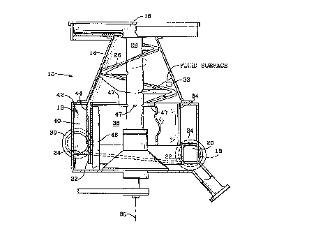
The screening device 10 of Figure 1 corres-
ponds, in general, to the same as disclosed in U.S.
Patent No. 5,143,220, issued September 1, 1992, to
Douglas L.G. Young and Donald B. Johnson, for "Apparatus
for Screening to Remove Knots from a Fluid Borne Slurry
of Fibers and Knots". It comprises a
~12~778
Docket No. 1469-IR-PA
housing having a lower, cylindrical extension 12, and an
upper, truncated cone extension 14. A fluid-free, coarse
particle chamber 16 is fixed atop extension 14. Conduit
18 is the slurry inlet; the same communicates with an
inlet chamber 20. Inlet chamber 20 is bounded by an
inner wall 22, extension 12, and a roof 24 spiraling
downward from inlet 18 until it approaches the bottom of
the inner wall 22 where it ends. The screw flight 26 is
; for the transport of rejects to chamber 16; flight 26 is
rotated by rotor 28. An outlet 30 carries the acceptable
slurry and fibers off from the device 10, and a port 32
admits wash liquor into the extension 14. A perforated
screen 34 is rotatable within the extension 12, about an
axis 36. It confines a feed chamber 38 therewithin, and
is surrounded by an accepts chamber 40. As priorly
noted, reference may be had to Patent No. 5,143,220 for a
full understanding of the nature and function of the
device 10.
The backwash means 42, according to an embodiment
thereof, is incorporated with the screening device 10.
It comprises a hydrofoil 44 and a vane 46, the former set
in proximate adjacency to the screen 34 in the accepts
chamber 40, and the latter being set in proximate
adjacency to the screen 34 in the feed chamber 38. The
hydrofoil 44 and vane 46 are in juxtaposition, straddling
the screen 34 therebetween. The uppermost end of the
... . .
~12~8
Docket No. 1469-IR-PA ~;
:
vane 46 defines a clearance for limbs 47 which join the
screen 34 to the rotor 28 for effecting rotation of the
screen 34.
Functioning of the backwash means 42 can be
understood with reference to Figure 2. In Patent No.
5,143,220, a hydrodynamic foil 48, axially coextensive
with, and positioned outboard of the screen 34, albeit in
close proximity thereto, was disclosed. As the rotating
screen 34 passed the foil 48, the slurry passing between
the screen 34 and foil 48 received a pressure pulse which
contributed to an expelling of such slurry-borne
substances which plugged the apertures in the screen 34.
As priorly explained, such a foil 48 generates two,
successive pulses.
The first of these is a positive, increased
pressure, pulse, and this is followed by a negative,
decreased pressura pulse. The resultant effect, in this
configuration, was to produce a backwash flow surge
contributory to a cleansing of the screen 34 but, also as
noted priorly, the flow surge was limited by the low
relative velocity of hydrofoil and screenplate,
compatible with acceptable reject liquor content,
turbulence and foaming of the liquor, the aforesaid
cavitation during the negative pulse, and the accept flow
surge which diminished slurry separation efficiency.
~124778
Docket No. 1469-IR-PA
Backwash means 42 offers an improvement over the
functioning of the foil 48 of Figure 2, and can be seen
to better advantage in Figures 3 and 4. Backwash means
42 comprises the aforementioned hvdrofoil 44 and vane 46,
5 both shown in cross-section in Figure 3. Foil 44 is
stationary in the accepts chamber 40, being fixed (by
means not shown) in extension 12 (Figure 1), and the vane
46 is stationary in the feed chamber 38, secured to
extension 12 (by means not shown). ~ydrofoil 44 is
10 curved, to conform, generally, to the curvature of the
thereadjacent screen 34, and has an inboard relief 50
formed therein which extends through approximately half
the width thereof. The relief has a termination which
defines a wall 52, the latter extending substantially
15 normal to the outer surface 54 of the screen 34. The
vane 46, too, has its width extending normal to the
inboard surface 56 of the screen 34. As Figure 4 shows,
the hydrofoil 44 and vane 46 extend substantially the
full depth of the screen 34, and preferably have a spiral
20 angle such that both members are self-clearing of
particles which may otherwise clog the clearance to the
screenplate.
Vane 46 comprises a wall which serves as a barrier
to slurry flow. It creates a stagnation pressure in the
25 slurry, at "A", which causes the first surge flow of the
.: : . . . ~
~12477~
Docket No. 1469-IR-PA
slurry, as indicated by the heavy-line arrow "a", through
- the screen 34, from the feed chamber 38, into the relief
50 of the hydrofoil 44. A relative low pressure of the
- slurry obtains in the relief 50 but, with centrifugal-
forced flow, the slurry encounters the flow barrier wall
52 of the hydrofoil 44. Here again, a stagnation
pressure is created, at "B", which causes a second surge
flow of the slurry through the screen 34, as indicated by
the heavy-line arrow "b", from the outboard surface
thereof, into the feed chamber 38. In the lee of the
vane 46 a low pressure obtains and, as a consequence
thereof, the second surge flow, addressed to the lee of
the vane 46, is driven by a cumulative pressure and
provides a backwashing of the screen of enhanced duration
and amplitude.
Rotation of the screen 34, and the slurry flow
direction, is shown by the broken arrows at the left-hand
side of Figure 3, and the slurry flow direction from the
feed chamber 38 to the accepts chamber 40 is shown by the
broken arrow at the right-hand side of Figure 3.
The first surge flow "a" has the desirable effect of
increasing the mean tangential velocity component of the
slurry entering the relief 50 of the hydrofoil 44, and
thus tends to increase the stagnation pressure at "B".
~ ~. . : : :
: ~ :
. .,
. . .
. ~.:, . . .
~ 2~778
Docket No. 1469-IR-PA
Thus, there is a beneficial enhancement of the energy of
the backwash flow surge "b" resulting from an additional
increase in driving pressure thereof. In turn, this
results from the relative location of the stagnation
pressure at "A" at the vane 46 in the feed chamber 38,
and the inflowing zone of the relief 50 of the hydrofoil
44 in the accepts chamber 40. The second surge flow "b"
is the backwashing which clears away those substances
which tend to clog the apertures in the screen 34.
The invention teaches the benefit of employing pairs
of hydrofoils (i.e., a hydrofoil 44 and a vane 46) which
cooperate in function. With a pair thereof located on
opposite sides of the screen 34, the positive, increased
pressure pulse of the first one acts cumulatively with
the negative, decreased pressure pulse of the second one,
to provide a backwash wave of enhanced amplitude and/or
duration, and results in a minimal accept flow surge.
Some of the benefits of the invention are: freedom from
cavitation, increased stability of screen operation, and
lower relative velocities, the latter offering lower
power consumption, a reduced wear rate, and reduced
maintenance cost and downtime. Additionally, and
significantly, the slurry screening is rendered more
efficient.
.
:'' .
~124778
Docket No~ 1469-IR-PA
; While I have described my invention in connection
with specific embodiments thereof, it is to be clearly
understood that this is done only by way of example, and
not as a limitation to the scope of the invention, as set
; 5 forth in the aspects thereof, and in the appended claims.
For example, while the screen 34 is shown as rotatable,
and the vane 46 and hydrofoil fixed, the screen could be
fixed and the vane 46 and hydrofoil 44 rotatable
therealong and thereabout. Too, although the accept flow
direction is shown outwardly, it could just as well be
inwardly. The screen 34 herein is cylindrical, but it
could be a planar disc, or frustoconical and, as noted,
fixed or movable, with the vane 46 and the hydrofoil 44
movable or fixed in relation thereto. Too, the invention ~ ;
can be practiced in an arrangement in which the screen 34
rotates in one direction, for instance clockwise, and the
pair of hydrofoils (i.e., vane 46 and foil 44) rotate in
the opposite, counterclockwise direction. In such an ~ -
arrangement, the rotary speed of the screen and that of
the hydrofoils could be substantially halved. Such
relatively lower velocities could offer even further
power consumption savings. Clearly, too, in an
alternative arrangement, the vane 46 could be arranged in
proximity to the outer surface of the screen 34, and the
foil 44 disposed in proximity to the inner surface of the
.. . ~ .
'~ .' '
~t2~778
. Docket No. 1469-IR-PA
screen (with the cross-section thereof reversed, so that
; the relief 50 and wall 52 interface the screen 34). All
such alterations and differing embodiments of the
invention, as suggested herein by my disclosure, are
deemed to be within the ambit of my invention and
enhanced by the appended claims.
.. ., ,, ~ ' ~,:,
:
:: . . ..
~ . ~
.