Language selection

Search

Patent 2124952 Summary

Third-party information liability

Some of the information on this Web page has been provided by external sources. The Government of Canada is not responsible for the accuracy, reliability or currency of the information supplied by external sources. Users wishing to rely upon this information should consult directly with the source of the information. Content provided by external sources is not subject to official languages, privacy and accessibility requirements.

Claims and Abstract availability

Any discrepancies in the text and image of the Claims and Abstract are due to differing posting times. Text of the Claims and Abstract are posted:

  • At the time the application is open to public inspection;
  • At the time of issue of the patent (grant).
(12) Patent: (11) CA 2124952
(54) English Title: SONIC OR ULTRASONIC TRANSDUCER
(54) French Title: TRANSDUCTEUR ACOUSTIQUE
Status: Expired and beyond the Period of Reversal
Bibliographic Data
(51) International Patent Classification (IPC):
  • H04R 17/00 (2006.01)
  • B06B 1/06 (2006.01)
(72) Inventors :
  • FLOGEL, KARL (Germany)
(73) Owners :
  • ENDRESS U. HAUSER GMBH U. CO.
(71) Applicants :
  • ENDRESS U. HAUSER GMBH U. CO. (Germany)
(74) Agent: SMART & BIGGAR LP
(74) Associate agent:
(45) Issued: 1998-04-28
(86) PCT Filing Date: 1993-09-24
(87) Open to Public Inspection: 1994-04-14
Examination requested: 1994-10-19
Availability of licence: N/A
Dedicated to the Public: N/A
(25) Language of filing: English

Patent Cooperation Treaty (PCT): Yes
(86) PCT Filing Number: PCT/EP1993/002605
(87) International Publication Number: WO 1994007615
(85) National Entry: 1994-06-01

(30) Application Priority Data:
Application No. Country/Territory Date
P 42 33 256.7 (Germany) 1992-10-02

Abstracts

English Abstract


The sonic or ultrasonic transducer includes a circular
piezo-ceramic disk capable of generating radial oscillations,
and a metal ring, which embraces in tight close fitting
relationship the circumferential surface area of the disk to
form a radial oscillator in conjunction with the disk. The
sonic or ultrasonic transducer formed in this manner has an
emission surface corresponding to the entire surface area of
the piezo-ceramic disk and metal ring, and displays a radial
resonant frequency which is lower than that of the
piezo-ceramic disk.


French Abstract

Le transducteur sonique ou ultrasonique comprend un disque piézo-céramique circulaire capable de produire des oscillations radiales et un anneau métallique qui entoure en ajustement serré la surface circonférentielle du disque pour former un oscillateur radial en conjugaison avec le disque. Le transducteur sonique ou ultrasonique ainsi formé a une surface d'émission correspondant à toute la surface du disque piézo-céramique et de l'anneau métallique et affiche une fréquence de résonance radiale inférieure à celle du disque piézo-céramique.

Claims

Note: Claims are shown in the official language in which they were submitted.

THE EMBODIMENTS OF THE INVENTION IN WHICH AN EXCLUSIVE
PROPERTY OR PRIVILEGE IS CLAIMED ARE DEFINED AS FOLLOWS:
1. A sonic or ultrasonic transducer comprising
a circular piezo-ceramic disk capable of generating
radial oscillations and having a circumferential surface, and
a metal ring surrounding the piezo-ceramic disk,
wherein the metal ring embraces in tight close fitting
relationship the circumferential surface of the piezo-ceramic
disk to form a radial oscillator in conjunction with the
piezo-ceramic disk.
2. The sonic or ultrasonic transducer of claim 1,
wherein the metal ring is secured to the piezo-ceramic disk by
shrinking the metal ring.
3. The sonic or ultrasonic transducer of claim 1,
wherein the metal ring is composed of aluminum.
4. The sonic or ultrasonic transducer of claim 1,
wherein the radial oscillator includes one end face and
further comprising an adaptive layer applied onto the one end
face of the radial oscillator formed by the piezo-ceramic disk
and the metal ring.
5. The sonic or ultrasonic transducer of claim 2,
wherein the metal ring is composed of aluminum.
- 5 -

6. The sonic or ultrasonic transducer of claim 2,
wherein the radial oscillator includes a first end face and a
second end face and further comprising an adaptive layer
applied onto the first end face of the radial oscillator.
7. The sonic or ultrasonic transducer of claim 3,
wherein the radial oscillator includes a first end face and a
second end face and further comprising an adaptive layer
applied onto the first end face of the radial oscillator.
8. A sonic or ultrasonic transducer comprising
a piezo-ceramic disk capable of generating radial
oscillations and having a disk radial resonant frequency and a
circumferential surface, and
a metal ring surrounding the piezo-ceramic disk,
wherein the metal ring and the piezo-ceramic disk form a
radial oscillator having an oscillator radial resonant
frequency which is lower than the disk radial resonant
frequency.
9. The sonic or ultrasonic transducer of claim 8,
wherein the radial oscillator has an oscillator diameter and
the oscillator radial resonant frequency is lower than a
radial resonant frequency of a second piezo-ceramic disk
having a diameter equal to the oscillator diameter.
10. The sonic or ultrasonic transducer of claim 8,
wherein the oscillator radial resonant frequency is a zero-
-6-

order resonant frequency.
11. The sonic or ultrasonic transducer of claim 8,
wherein the piezo-ceramic disk includes a first end face and a
second end face and further comprising a first electrode
situated on the first end face, a second electrode situated on
the second end face, and means for providing an alternating
current to the first and second electrodes to excite the
piezo-ceramic disk and oscillate the radial oscillator so that
the oscillations have a Gaussian amplitude distribution.
- 7 -

Description

Note: Descriptions are shown in the official language in which they were submitted.


212~2
SONIC OR ULTRASONIC TRANSDUCER
This invention relates to a sonic or ultrasonic transducer
which includes a circular piezo-ceramic disk capable of
generating oscillations, and a metal ring, surrounding the
piezo-ceramic disk.
The operating frequency of a sonic or ultrasonic transducer
which includes a piezo-ceramic disk capable of generating
radial oscillations generally corresponds to the radial
resonant frequency of the piezo-ceramic disk, which is
dictated by the dimensions of the piezo-ceramic disk. The
diameter of the piezo-ceramic disk further determines the
magnitude of the sonic emission surface, which determines
the apex angle of the produced sonic radiation. In an
ultrasonic transducer of the nature set out above known from
DE-PS 25 41 492, a foam plate having a substantially larger
surface area than the piezo-ceramic disk is adhesively
bonded to an end face of the piezo-ceramic disk, to serve as
an adaptive layer for reducing the apex angle dictated by
the dimensions of the piezo-ceramic disk. The protruding
region of the foam plate is connected to the metal ring
surrounding the piezo-ceramic disk which serves as a
weighting ring and in order for the interface between the
weighting ring and the piezo-ceramic disk to constitute a
nodal surface which remains virtually immobile during the
operation of the ultrasonic transducer. In this way the
entire exposed end face of the adaptive layer is caused to
oscillate virtually in phase with the piezo-ceramic disk.
The metal ring may not touch the piezo-ceramic disk in order
to fulfil this function as a weighting ring. Although the
sonic emission area of this prior art ultrasonic transducer
is increased in relation to the surface area of the piezo-
ceramic disk, the operating frequency remains dependent on
the diameter of the piezo-ceramic disk. A reduction in the
operating frequency is only attainable by using a larger
piezo-ceramic disk.

21 24952
The object of the present invention is the provision
of a sonic or ultrasonic transducer of the nature set out
above, which for a given set of dimensions of the piezo-
ceramic disk produces a lower operating frequency in relation
to the radial resonant frequency of the piezo-ceramic disk.
This object is met according to one aspect of the
invention in that the metal ring embraces in tight close
fitting relationship the circumferential surface area of the
piezo-ceramic disk to form a radial oscillator in conjunction
with the disk.
In a sonic or ultrasonic transducer according to the
invention the metal ring is firmly coupled to the piezo-
ceramic disk so that both components constitute a mass-spring
element performing radial oscillations in unison. The entire
surface area of the radial oscillator formed in this manner
functions as an emitting surface oscillating completely in
phase, producing a substantially Gaussian distribution of
amplitudes, the sonic emission thereby displaying a small apex
angle without interfering secondary lobes. The radial
resonant frequency of this radial oscillator is lower,
however, than the radial resonant frequency of the piezo-
ceramic disk. More particularly it is dependent on the
dimensions of the metal ring. It is accordingly feasible to
manufacture sonic or ultrasonic transducers for different
operating frequencies by means of identical piezo-ceramic
disks by appropriately dimensioning the metal ring.
The metal ring is preferably connected to the piezo-
ceramic disk by being shrunk on.
23292-81

21 24952
An adaptive layer may be applied in known fashion
onto the one end face of the radial oscillator formed by the
piezo-ceramic disk and the metal ring.
According to another aspect, the invention provides
a sonic or ultrasonic transducer comprising a piezo-ceramic
disk capable of generating radial oscillations and having a
disk radial resonant frequency and a circumferential surface,
and a metal ring surrounding the piezo-ceramic disk, wherein
the metal ring and the piezo-ceramic disk form a radial
oscillator having an oscillator radial resonant frequency
which is lower than the disk radial resonant frequency.
- 2a -
23292-81
A
.-,, -~

2124952
Further features and advantages of the invention will be
apparent from the following description of an embodiment
with reference to the drawings. In the drawings:
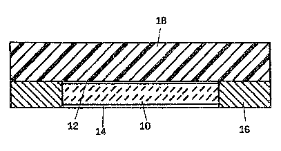
- Figure 1 shows a sonic or ultrasonic transducer according
to the invention,
- Figure 2 shows the amplitude distribution over the
emitting surface of the sonic or ultrasonic transducer of
Figure 1,
- Figure 3 shows the characteristic frequency curve of the
piezo-ceramic disk of the sonic or ultrasonic transducer
of Figure 1, and
- Figure 4 shows the characteristic frequency curve of the
entire sonic or ultrasonic transducer of Figure 1.
The sonic or ultrasonic transducer shown in Figure 1
includes a circular piezo-ceramic disk 10 having metal
electrodes 12, 14 applied to both of its end faces. The
piezo-ceramic disk 10 is surrounded by a metal ring 16 which
is arranged in tight close fitting relationship with the
circumferential surface of the piezo-ceramic disk. The metal
ring 16 may be connected to the piezo-ceramic disk 10 by
having been shrunk on for example, i.e. the ring is applied
around the piezo-ceramic disk in a heated state, and firmly
encircles it after cooling. The metal ring 16 may be of
aluminium, for example.
Whenever an alternating current is applied to the electrodes
12 and 14 the piezo-ceramic disk 10 is excited to produce
radial oscillations. As a result of the intimate coupling
with the metal ring 16 these radial oscillations are
transferred to the metal ring whereby the entire assembly
functions as a single radial oscillator. In order to ensure
that the sonic or ultrasonic wave is emitted substantially
to one side only an adaptive layer 18 having a thickness

~12~s~
- 4 -
corresponding to a quarter of the wave length of the sonic
or ultrasonic wave produced is applied to that one end face
of the piezo-ceramic disk 10 and the metal ring 16.
Figure 2 shows the amplitude distribution of the
oscillations across the entire surface area of the radial
oscillator comprising the piezo-ceramic disk 10 and the
metal ring 16. The amplitude distribution complies
substantially with the desired Gaussian distribution. The
oscillations are in phase across the entire surface area so
that a radiation diagram without interfering secondary lobes
is obtained, having an apex angle determined by the overall
surface area of the radial oscillator.
Figure 3 shows the frequency characteristic curve for the
piezo-ceramic disk 10 in which the radial resonant frequency
is denoted as fR. Figure 4 shows on the same scale the
frequency characteristic curve for the radial oscillator
formed by the piezo-ceramic disk 10 and the metal ring 16.
It is evident that this radial oscillator has substantially
the same frequency characteristics as the piezo-ceramic disk
10 whereas the radial resonance frequency is substantially
lower; the latter lies intermediate between the radial
resonance frequency of the piezo-ceramic disk 10 and the
radial resonance frequency of the metal ring 16. It is
accordingly feasible to obtain a desired reduced radial
resonance frequency by means of the same piezo-ceramic disk
10 by appropriately dimensioning the metal ring 16.
The diagrams of Figures 2, 3 and 4 make it clear that the
radial oscillator comprising the piezo-ceramic disk 10 and
the metal ring 16 with regard to amplitude distribution,
phase distribution and frequency, operates in the same
manner as a piezo-ceramic disk having a larger diameter than
the piezo-ceramic disk 10.

Representative Drawing
A single figure which represents the drawing illustrating the invention.
Administrative Status

2024-08-01:As part of the Next Generation Patents (NGP) transition, the Canadian Patents Database (CPD) now contains a more detailed Event History, which replicates the Event Log of our new back-office solution.

Please note that "Inactive:" events refers to events no longer in use in our new back-office solution.

For a clearer understanding of the status of the application/patent presented on this page, the site Disclaimer , as well as the definitions for Patent , Event History , Maintenance Fee  and Payment History  should be consulted.

Event History

Description Date
Time Limit for Reversal Expired 2007-09-24
Letter Sent 2006-09-25
Inactive: IPC from MCD 2006-03-11
Grant by Issuance 1998-04-28
Inactive: Final fee received 1997-12-12
Pre-grant 1997-12-12
Notice of Allowance is Issued 1997-10-22
Letter Sent 1997-10-22
Inactive: Application prosecuted on TS as of Log entry date 1997-10-16
Inactive: Status info is complete as of Log entry date 1997-10-16
Inactive: First IPC assigned 1997-09-12
Inactive: IPC removed 1997-09-12
Inactive: IPC assigned 1997-09-12
Inactive: Approved for allowance (AFA) 1997-09-12
Request for Examination Requirements Determined Compliant 1994-10-19
All Requirements for Examination Determined Compliant 1994-10-19
Application Published (Open to Public Inspection) 1994-04-14

Abandonment History

There is no abandonment history.

Maintenance Fee

The last payment was received on 1997-07-24

Note : If the full payment has not been received on or before the date indicated, a further fee may be required which may be one of the following

  • the reinstatement fee;
  • the late payment fee; or
  • additional fee to reverse deemed expiry.

Please refer to the CIPO Patent Fees web page to see all current fee amounts.

Fee History

Fee Type Anniversary Year Due Date Paid Date
MF (application, 4th anniv.) - standard 04 1997-09-24 1997-07-24
Final fee - standard 1997-12-12
MF (patent, 5th anniv.) - standard 1998-09-24 1998-08-24
MF (patent, 6th anniv.) - standard 1999-09-24 1999-08-13
MF (patent, 7th anniv.) - standard 2000-09-25 2000-08-14
MF (patent, 8th anniv.) - standard 2001-09-24 2001-08-17
MF (patent, 9th anniv.) - standard 2002-09-24 2002-08-15
MF (patent, 10th anniv.) - standard 2003-09-24 2003-08-19
MF (patent, 11th anniv.) - standard 2004-09-24 2004-08-23
MF (patent, 12th anniv.) - standard 2005-09-26 2005-08-25
Owners on Record

Note: Records showing the ownership history in alphabetical order.

Current Owners on Record
ENDRESS U. HAUSER GMBH U. CO.
Past Owners on Record
KARL FLOGEL
Past Owners that do not appear in the "Owners on Record" listing will appear in other documentation within the application.
Documents

To view selected files, please enter reCAPTCHA code :


To view images, click a link in the Document Description column. To download the documents, select one or more checkboxes in the first column and then click the "Download Selected in PDF format (Zip Archive)" or the "Download Selected as Single PDF" button.

List of published and non-published patent-specific documents on the CPD .

If you have any difficulty accessing content, you can call the Client Service Centre at 1-866-997-1936 or send them an e-mail at CIPO Client Service Centre.


Document
Description 
Date
(yyyy-mm-dd) 
Number of pages   Size of Image (KB) 
Cover Page 1995-06-10 1 86
Claims 1995-06-10 1 56
Abstract 1995-06-10 1 44
Description 1995-06-10 4 298
Drawings 1995-06-10 2 93
Cover Page 1998-04-21 1 48
Description 1997-08-20 5 196
Abstract 1997-08-20 1 16
Claims 1997-08-20 3 75
Representative drawing 1998-04-21 1 15
Commissioner's Notice - Application Found Allowable 1997-10-22 1 165
Maintenance Fee Notice 2006-11-20 1 173
Correspondence 1997-12-12 1 28
Maintenance fee payment 1996-08-12 1 37
Maintenance fee payment 1995-08-11 1 37
Courtesy - Office Letter 1995-01-11 1 54
Prosecution correspondence 1994-06-01 6 226
International preliminary examination report 1994-06-01 4 139
Prosecution correspondence 1994-10-19 1 41
National entry request 1994-06-28 3 84
Prosecution correspondence 1997-07-22 2 43
Examiner Requisition 1997-03-11 2 75
National entry request 1994-06-01 2 98