Language selection

Search

Patent 2125072 Summary

Third-party information liability

Some of the information on this Web page has been provided by external sources. The Government of Canada is not responsible for the accuracy, reliability or currency of the information supplied by external sources. Users wishing to rely upon this information should consult directly with the source of the information. Content provided by external sources is not subject to official languages, privacy and accessibility requirements.

Claims and Abstract availability

Any discrepancies in the text and image of the Claims and Abstract are due to differing posting times. Text of the Claims and Abstract are posted:

  • At the time the application is open to public inspection;
  • At the time of issue of the patent (grant).
(12) Patent: (11) CA 2125072
(54) English Title: DECKET STORAGE FOR PROP WRENCH AND NUT
(54) French Title: SUPPORT DE MONTAGE DE PROPULSEUR ELECTRIQUE AVEC LOGEMENT DE REMISAGE POUR CLE ET ECROU D'HELICE
Status: Expired and beyond the Period of Reversal
Bibliographic Data
(51) International Patent Classification (IPC):
  • B63B 25/00 (2006.01)
  • B63B 17/00 (2006.01)
(72) Inventors :
  • TYLER, WILLIAM CALVIN (United States of America)
(73) Owners :
  • ZEBCO CORPORATION
(71) Applicants :
  • ZEBCO CORPORATION (United States of America)
(74) Agent: RICHES, MCKENZIE & HERBERT LLP
(74) Associate agent:
(45) Issued: 1997-04-15
(22) Filed Date: 1994-06-03
(41) Open to Public Inspection: 1994-12-05
Examination requested: 1994-11-07
Availability of licence: N/A
Dedicated to the Public: N/A
(25) Language of filing: English

Patent Cooperation Treaty (PCT): No

(30) Application Priority Data:
Application No. Country/Territory Date
08/072,247 (United States of America) 1993-06-04

Abstracts

English Abstract


The arrangement and receptacle storing the prop wrench and spare prop nut
allow the fisherman to store the necessary tools to quickly replace a prop on a
trolling motor on the spot. The prop wrench has three principal components--the
prop wrench base, the prop pins, and the prop wrench cap. The prop wrench base
has storage compartments to store the spare prop pins, which are secured in place
by the prop wrench cap. Both the prop wrench and the spare prop nut are stored
in the decket. The decket has preformed molded recesses which correspond,
respectively, to the shape of the prop wrench and the prop nut. The spare prop nut
and the prop wrench are locked into place within the decket by a lip on the prop
wrench base that snaps into a locking relationship with the snap fit on the decket,
and is further secured by two tabs located opposite the snap fit within the recess
and above the prop wrench assembly. The decket performs its normal function of
support for the trolling motor while also providing a handy location to store the
equipment described.


Claims

Note: Claims are shown in the official language in which they were submitted.

WE CLAIM:
1. In combination, a housing for storage and a prop
nut and wrench for a boat trolling motor, said housing
supporting a boat trolling motor when in use, comprising:
a housing mounted to a boat, said housing having
a recess;
a securing member on said housing;
a prop nut, said recess adapted to accept said
nut so as to place said nut within said housing;
a prop wrench, said recess adapted to accept said
wrench so as to place said wrench at least in part in said
recess; and
said securing member securing said prop nut and
said prop wrench to said housing.
2. The combination of claim 1, wherein:
said nut is shielded from exposure to the
elements when secured in said recess in said housing and
stacked below said wrench.
3. The combination of claim 2, wherein said recess
further comprises:
a first cavity shaped to conform to the periphery
of said nut; and
a second cavity adjacent said first cavity shaped
to conform to at least a portion of the periphery of said
wrench.
4. The combination of claim 3, wherein:
said securing member is disposed at least in
portion said second cavity for holding said prop wrench in
said second cavity.
5. The combination of claim 4, further comprising:
a mandrel in said first cavity for accepting said

prop nut therein for aiding in insertion and alignment of
said nut in said first cavity.
6. The combination of claim 5, wherein:
said prop wrench further comprises:
a base;
an engagement surface on said base; and
said securing member comprising a flexible snap
to engage said engagement surface for selectively securing
said wrench in said second cavity.
7. The combination of claim 6, wherein:
said housing having a guiding member for a troll
motor when the troll motor is in its stowed position;
said guiding member disposed further from the
boat on said housing than said first and second cavities;
and
said first and second cavities disposed
contiguously in said housing.
8. The combination of claim 7, wherein:
said prop wrench having at least one compartment
therein;
at least one prop pin, said pin adapted for
storage in said compartment;
a cover mounted to said prop wrench to secure
said pin in said compartment; and
said second cavity formed to accept said cover
mounted to said prop wrench for storage thereof to said
housing.
9. A method for storing spare boat components in a
boat having a trolling motor, comprising:
mounting a housing to the boat which includes a
pivoting linkage to support a trolling motor in two
positions;

providing a storage compartment in said housing;
providing at least one extending member from said
housing adjacent to said compartment;
inserting the spare components at least in part
into said storage compartment;
securing the components to said housing; and
using said extending member to support the
trolling motor adjacent said compartment when the trolling
motor is in use and the components stored in said
compartment.
10. The method of claim 9, wherein:
said inserting step further comprises placing a
trolling motor prop nut into said compartment;
overlaying a prop wrench on the prop nut; and
said securing step further comprises using a
housing-mounted snap to secure the prop wrench to said
housing.
11. The method of claim 10, further comprising the
steps of:
providing at least one storage area in said prop
wrench;
storing at least one prop in said area; and
securing the prop pin in said area.
12. The method of claim 11, further comprising the
steps of:
shielding the prop nut from weather exposure by
virtue of said overlaying of the prop wrench in said
compartment; and
shielding the prop pin from weather exposure by
a cover applied over said storage area.
13. The method of claim 12, further comprising the
steps of:

providing a relief in said housing higher in said
housing than said compartment;
shaping the compartment on different levels to
the shape of the prop nut and prop wrench; and
leaving the relief in the housing exposed for
support of a stowed motor unit after securing the prop nut
and prop wrench to said shaped compartment.
14. The method of claim 13, further comprising the
steps of:
using a snap fit to secure the prop wrench to
said compartment; and
positioning the prop wrench flush with the open
top of said compartment for securing it with the snap fit.
15. A multipurpose apparatus for a fishing boat
having a trolling motor, comprising:
a deck-mounted housing having an upper and lower
end and at least one extending member extending from said
upper end;
a support structure for the trolling motor
movably located adjacent the top end of said housing;
said housing formed having an opening, said
opening shaped to accept a prop nut and prop wrench for a
trolling motor;
said opening located between said support and
said lower end in a manner so as to allow said extending
member on said housing to support said structure adjacent
said opening when the trolling motor is in use; and
a securing member mounted adjacent said opening
for securing a prop nut and prop wrench stowed therein.
16. The apparatus of claim 15, wherein:
said opening having a plurality of shapes
comprising:
a first shape formed to the shape of a prop nut

closest to said lower end of said housing;
a second shape between said first shape and said
support formed to the shape of a prop wrench; and
said combined shapes being substantially occupied
by the prop nut and prop wrench when secured therein
without obstruction of the functioning of said support.
17. The apparatus of claim 16, wherein said support
further comprises:
a notch formed in said housing adapted to accept
a portion of a trolling motor assembly.

Description

Note: Descriptions are shown in the official language in which they were submitted.


2 1 ~ 5072
TITLE: DECKET STOR~GE FOR PROP WRENCH AND N~lT
INVENIOR: WILLIAM CALVIN TYLER
FTFT r) OF THF INVENTION
The feld of this invention relates generally to storage of fishing tools, more
particularly, to the arrangement for storage of a prop wrench and spare prop nut on
the deck of a boat.
RAcKGRouND OF THF INVFNTION
Storage space in a fishing boat is sparse and when repairs are necessary,
quick access to the tools is essential. In the past, tools have been stored in various
locales in the boat. This entailed use of valuable space, and sometimes it becomes
10 difficult to locate the tools. Storage bags can be easily soaked by salt or fresh
water, which deteriorates the tools and renders them useless.
U.S. Patent No. 5,029,706 illustrates a wrench storage arrangement within
a router-housing mech~ni.~m. The top of the router housing is constructed to form
apertures conforming to the shape of the wrench handle. A pair of beams forming
15 longitudinal ribs that lie perpendicular to the apellures are molded into the top of
the housing. Notches are provided on both side surfaces of the wrench handle.
The wrench handle is secured in the router housing by extending the wrench handle

2 1 25~7~
through one of the apertures. The handle extends into the cavity and dowllw~rdly
deflects the flexible beams. The wrench handle continues to extend out of the
other aperture. The notches then align with the ribs and engage the wrench in a
detent manner so that the wrench is releasably retained in a stored position within
S the housing. Although the apertures in this invention are designed to fit the shape
of the wrench handle, interaction of the wrench handle, ribs, notches, and both
apellules is required to secure the tool in the router housing.
U.S. Patent No. 5,137,481 provides a pocket on a outboard motor tote for
tools. However, this tote with the tool pocket is removed when the motor is in
10 operation. The tool storage on this invention entails a limited-space pocket that
is covered only by a flap and secured by a mechanical fastener. Space is limited
and access is dif~lcult because the tote must be stored while the boat is in use.
U.S. Patent No. 4,372,243 is a netted framed mech~ni~m that is suspended
from the stern of the boat while the fisherman repairs the motor. The function of
15 this invention is to prevent loss of tools, not to store tools on a permanent basis.
The present invention provides a space-saving housing arrangement in the
decket for a prop wrench, prop pins, and spare prop nut. The fisherman can easily
make a repair using these spares without having to come to shore. The decket is
part of a deck-mounted structure that is used in positioning a trolling motor unit
20 on a boat deck prior to stowing and during use. This is advantageous to the

-- .
2125072
fisherman because access to the tool is easy and the
fisherman always knows where the tools are. The storage
arrangement does not interfere with the mechanical function
of the decket. The prop pins are isolated from the weather
inside the prop wrench. The prop nut is similarly isolated
by the prop wrench.
SUMMARY OF THE INVENTION
The present invention allows the fisherman to
store the necessary tools to quickly replace the prop on
the trolling motor on the spot. The prop wrench assembly
has three principal components, the prop wrench base, prop
pins, and prop wrench cap. The prop wrench base provides
storage for two prop pins, which are secured in place by
the prop wrench cap. Both the prop wrench assembly and the
spare prop nut are stored in the decket. The decket has
preformed recesses which correspond, respectively, to the
shape of the prop wrench assembly and the prop nut. The
prop nut and the prop wrench assembly are locked into place
within the decket by a lip on the prop wrench assembly that
snaps into a locking relationship with the snap fit located
above the recess.
Accordingly in one aspect the invention resides
in combination, a housing for storage and a prop nut and
wrench for a boat trolling motor, said housing supporting
a boat trolling motor when in use, comprising:
a housing mounted to a boat, said housing having
a recess;
a securing member on said housing;
a prop nut, said recess adapted to accept said
nut so as to place said nut within said housing;
a prop wrench, said recess adapted to accept said
wrench so as to place said wrench at least in part in said
recess; and
said securing member securing said prop nut and
said prop wrench to said housing.
B

21 25072
In another aspect the invention resides in a
method for storing spare boat components in a boat having
a trolling motor, comprising:
mounting a housing to the boat which includes a
pivoting linkage to support a trolling motor in two
positions;
providing a storage compartment in said housing;
providing at least one extending member from said
housing adjacent to said compartment;
inserting the spare components at least in part
into said storage compartment;
securing the components to said housing; and
using said extending member to support the
trolling motor adjacent said compartment when the trolling
motor is in use and the components stored in said
compartment.
In a further aspect the invention resides in a
multipurpose apparatus for a fishing boat having a trolling
motor, comprising:
a deck-mounted housing having an upper and lower
end and at least one extending member extending from said
upper end;
a support structure for the trolling motor
movably located adjacent the top end of said housing;
`said housing formed having an opening, said
opening shaped to accept a prop nut and prop wrench for a
trolling motor;
said opening located between said support and
said lower end in a manner so as to allow said extending
member on said housing to support said structure adjacent
said opening when the trolling motor is in use; and
a securing member mounted adjacent said opening
for securing a prop nut and prop wrench stowed therein.
BRIEF DESCRIPTION OF THE DRAWINGS
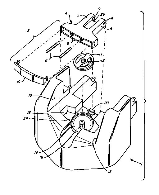
Figure 1 is an exploded isometric view of the
present invention.
3a

21 25072
Figure 2 is an isometric view showing the decket as mounted on a boat deck
as part of a trolling motor assembly.
Figure 3 is an elevational view showing a trolling motor support assembly
resting on the decket with the spare prop nut, prop pins, and prop wrench stored
S therein.
DF,TATT,F,D nESC~TPTION OF THF, PRF,FF,RF~F,n F,l~ROnIMF~
The apparatus is shown in Figure 1. The present invention is stored in a
recessed area on the upper surface of the decket 1, which functions to correctly
10 position the trolling motor unit, as shown in Figure 2. The apparatus is made of
three principal components--the prop wrench assembly 2, rece-sse.~ 14 and 16 in
the decket 1, and the locking mech~ni~m~ 20, 22, and 24 that secure the tools
inside recesses 14 and 16.
Prop wrench assembly 2 contains the prop wrench base 4, two spare prop
15 pins 6, two storage compartments 8 for storing the spare prop pins 6, and a prop
wrench cap 10 that secures spare prop pins 6 into the two storage co~,lpallll,ents
8. Prop wrench base 4, used to tighten spare prop nut 12 to a desired torque, is a
handle with two extensions 5 separated by the prop wrench lip 22. Indentations
9 on the tips of the extensions 5 are shaped to grip a prop nut 12 of a particular
20 design.

21 25()72
Prop pins 6, tubular in shape, can be used to key the prop to the armature
shaft to prevent the prop from freely rotating. Two elongated storage compart-
ments 8 corresponding in size to prop pins 6 are located on the top surface of prop
wrench base 4. Prop wrench cap 10 locks into the top surface of prop wrench base
S 4 to secure stored prop pins 6 into elongated storage compartments 8.
Two corresponding recesses, respective in size and shape to prop wrench
assembly 2 and spare prop nut 12, are preformed and molded into the top surface
of decket 1. Spare prop nut 12 is secured in place within recess 14 by a mandrel
18. Prop wrench assembly 2 fits into recess 16 and is stored on top of spare prop
nut 12. Lip 22 on prop wrench base 4 snaps into snap fit 20. Preferably, two tabs
located within recess 16 on the top surface of decket 1, opposite snap fit 20 and
above prop wrench assembly 2, releasably retain prop wrench assembly 2 and spare
prop nut 12 in place.
Decket 1 has a pair of wing walls 13 and 15 between which a support
15 mech~ni~m 17 (see Figure 3) can be set to perform the decket's ordinary function,
even while the spare nut 12 and wrench assembly 2 are in recesses 14 and 16.
The foregoing disclosure and description of the invention are illustrative and
explanatory thereof, and various changes in the size, shape, and materials, as well
as in the details of the illustrated con~lluction, may be made without departing
20 from the spirit of the invention.

Representative Drawing
A single figure which represents the drawing illustrating the invention.
Administrative Status

2024-08-01:As part of the Next Generation Patents (NGP) transition, the Canadian Patents Database (CPD) now contains a more detailed Event History, which replicates the Event Log of our new back-office solution.

Please note that "Inactive:" events refers to events no longer in use in our new back-office solution.

For a clearer understanding of the status of the application/patent presented on this page, the site Disclaimer , as well as the definitions for Patent , Event History , Maintenance Fee  and Payment History  should be consulted.

Event History

Description Date
Time Limit for Reversal Expired 2010-06-03
Letter Sent 2009-06-03
Inactive: IPC from MCD 2006-03-11
Letter Sent 2003-06-06
Letter Sent 2002-06-07
Letter Sent 1998-07-02
Grant by Issuance 1997-04-15
Application Published (Open to Public Inspection) 1994-12-05
All Requirements for Examination Determined Compliant 1994-11-07
Request for Examination Requirements Determined Compliant 1994-11-07

Abandonment History

There is no abandonment history.

Fee History

Fee Type Anniversary Year Due Date Paid Date
MF (patent, 3rd anniv.) - standard 1997-06-03 1997-06-03
MF (patent, 4th anniv.) - standard 1998-06-03 1998-05-28
MF (patent, 5th anniv.) - standard 1999-06-03 1998-06-03
MF (patent, 6th anniv.) - standard 2000-06-05 2000-05-23
MF (patent, 7th anniv.) - standard 2001-06-04 2001-05-18
MF (patent, 8th anniv.) - standard 2002-06-03 2002-05-02
MF (patent, 9th anniv.) - standard 2003-06-03 2002-05-21
MF (patent, 10th anniv.) - standard 2004-06-03 2003-05-21
MF (patent, 11th anniv.) - standard 2005-06-03 2005-05-09
MF (patent, 12th anniv.) - standard 2006-06-05 2006-05-08
MF (patent, 13th anniv.) - standard 2007-06-04 2007-05-07
MF (patent, 14th anniv.) - standard 2008-06-03 2008-05-07
Owners on Record

Note: Records showing the ownership history in alphabetical order.

Current Owners on Record
ZEBCO CORPORATION
Past Owners on Record
WILLIAM CALVIN TYLER
Past Owners that do not appear in the "Owners on Record" listing will appear in other documentation within the application.
Documents

To view selected files, please enter reCAPTCHA code :


To view images, click a link in the Document Description column. To download the documents, select one or more checkboxes in the first column and then click the "Download Selected in PDF format (Zip Archive)" or the "Download Selected as Single PDF" button.

List of published and non-published patent-specific documents on the CPD .

If you have any difficulty accessing content, you can call the Client Service Centre at 1-866-997-1936 or send them an e-mail at CIPO Client Service Centre.


Document
Description 
Date
(yyyy-mm-dd) 
Number of pages   Size of Image (KB) 
Abstract 1997-03-04 1 28
Claims 1997-03-04 5 152
Description 1997-03-04 6 225
Cover Page 1997-03-04 1 13
Drawings 1997-03-04 2 46
Cover Page 1995-06-08 1 22
Abstract 1995-06-08 1 26
Claims 1995-06-08 6 134
Description 1995-06-08 5 163
Drawings 1995-06-08 2 41
Representative drawing 1998-08-24 1 21
Maintenance Fee Notice 2009-07-15 1 171
Correspondence 2003-06-06 1 12
Correspondence 1998-07-02 1 12
Fees 1997-06-03 1 35
Correspondence 2002-06-07 1 13
Maintenance fee payment 1996-05-10 1 37
Prosecution correspondence 1994-06-03 24 697
Prosecution correspondence 1995-06-01 2 37
Prosecution correspondence 1995-08-14 3 60
Correspondence related to formalities 1997-02-05 1 38
Courtesy - Office Letter 1994-11-30 1 59
Courtesy - Office Letter 1995-01-25 1 58
Prosecution correspondence 1994-11-07 1 35