Language selection

Search

Patent 2125315 Summary

Third-party information liability

Some of the information on this Web page has been provided by external sources. The Government of Canada is not responsible for the accuracy, reliability or currency of the information supplied by external sources. Users wishing to rely upon this information should consult directly with the source of the information. Content provided by external sources is not subject to official languages, privacy and accessibility requirements.

Claims and Abstract availability

Any discrepancies in the text and image of the Claims and Abstract are due to differing posting times. Text of the Claims and Abstract are posted:

  • At the time the application is open to public inspection;
  • At the time of issue of the patent (grant).
(12) Patent: (11) CA 2125315
(54) English Title: DISPLAY SHELF ASSEMBLY
(54) French Title: ETAGERE
Status: Expired and beyond the Period of Reversal
Bibliographic Data
(51) International Patent Classification (IPC):
  • A47F 5/08 (2006.01)
  • A47B 96/02 (2006.01)
  • A47F 7/00 (2006.01)
(72) Inventors :
  • ERNETOFT, ULF (Canada)
(73) Owners :
  • ULF ERNETOFT
(71) Applicants :
  • ULF ERNETOFT (Canada)
(74) Agent: C.E. VAN STEINBURGVAN STEINBURG, C.E.
(74) Associate agent:
(45) Issued: 1997-04-08
(22) Filed Date: 1994-06-07
(41) Open to Public Inspection: 1995-02-13
Examination requested: 1994-11-21
Availability of licence: N/A
Dedicated to the Public: N/A
(25) Language of filing: English

Patent Cooperation Treaty (PCT): No

(30) Application Priority Data:
Application No. Country/Territory Date
08/105,116 (United States of America) 1993-08-12

Abstracts

English Abstract


In accordance with the present invention, a shelf assembly
is provided, which assembly is comprised by a pair of end
brackets, adapted for spaced mounting, in cantilever fashion,
on a slotted wall display area, and a shelf element secured to
a pair of such brackets, each bracket being provided with a
widened, flat horizontal upper surfaced, cantilevered, arm
element. A pair of such brackets being comprised by two
brackets having opposed, upturned edge flanges on one side only
of the flat portion, the upturned flanges being of sufficient
height to act as end stops for a shelf supported between the
bracket arms and secured to and resting on the flat portions of
the arms, the end stops preventing articles, supported on the
shelf, from being inadvertently pushed off the ends of the
shelf. In the assembly, adapted for display of cassettes,
cassette accepting channels are provided in the upper surface
of the shelf which support a plurality of cassettes in leaf-
through-observation arrangement. Preferably, the channels run
lengthwise of the shelf parallel to a shelf supporting display
board.


Claims

Note: Claims are shown in the official language in which they were submitted.

CLAIMS
1. A shelf assembly, for mounting on a vertically oriented
display board provided with horizontal slots having at least
the upper side undercut so as to accept hook in shelf brackets,
comprising a pair of spaced brackets each having an arm adapted
to project horizontally from and perpendicular to the display
board, each arm having a flat, shelf supporting upper side, the
bracket arms being provided with opposed, upstanding, flanges
on one side of each arm, each arm having, at its wall end a
vertically extending wall contacting surface, the wall
contacting surface having, at its upper side, an inturned-to-
the-wall part with an upturned hook end part adapted, when the
brackets are in position on a display board, to hook into the
undercut part of a horizontal slot on a slotted wall display
board, a shelf resting on and attached to the flat upper sides
of the pair of brackets to form a unitary assembly, and wherein
the flanges on the arms of the brackets act as outer shelf end
stops to prevent shelf supported items being, inadvertently,
pushed sideways off the shelf.
2. A shelf assembly, as claimed in Claim 1, wherein the shelf
is provided with a group of channels, in parallel arrangement,
in the upper side thereof, the channels being adapted to
support a plurality of cassettes in leaf-through-observation
arrangement.
3.(Amended) A shelf assembly, as claimed in Claim 2, wherein
the flanges extend above the bottoms of channels and the
channels run parallel to the outer surface of the display
board.
4. A shelf assembly, for mounting on a, vertically oriented,
wall display board provided with horizontal slots having, at
least, the upper side of a slot undercut so as to accept hook-
- 5 -

type shelf brackets, comprising a pair of spaced brackets each
having an arm adapted to project horizontally from and
perpendicular to the surface of the display board, each arm
having an extended, flat, upper shelf-supporting surface and an
upturned flange on one side thereof symmetrically opposed to
the flange on the other bracket arm, each arm having, at the
display board end of the arm, a vertically extending board
contacting surface the top of which is bent rearward and then
upward to provide a vertically extended surface adapted to fit
into and hook into the undercut portion of a slot, a shelf
resting on and secured to the flat upper surfaces of the
bracket arms with the flanges of the arms acting as outer end
stops for the shelf to prevent shelf supported items being
inadvertently pushed sideways off the shelf and wherein the
shelf is provided with a plurality of parallel channels in its
upper side, the channels being adapted to hold a plurality of
cassettes in spaced leaf-through-observation arrangement.
- 6 -

Description

Note: Descriptions are shown in the official language in which they were submitted.


2125315
DISPLAY SHELF ASSEMBLY
FIT~T-n OF TUT~ INVT~NTION
This invention relates to display shelves for the orderly
display of a plurality of items such as audio, video and
compact disc cassettes and the like. The items to be displayed
are arranged in appropriately sized and spaced channels
provided in the upper surface of the shelf per se. The shelf
assembly, which consists of the shelf element per se and end
supports therefor, is adapted to be readily mounted on a
vertically oriented, slotted, display board of the type
provided with horizontal, on side, L or T shaped slots
appropriately vertically spaced. Such slotted display boards
are readily obtainable and are widely used in wholesale and
retail display areas for small articles. There are various
brackets available, which are appropriately shaped for
insertion into the slot on a slotted board to provide a shelf
support bracket. or hook, arm projecting horizontally from and
perpendicular to the board. The known support arms are in the
form of a stiff rod or an, on edge, strap provided with a
shoulder, on its lower board contacting side, which shoulder
rests against the outer surface of the slotted board to hold
the arm in a horizontal cantilever position. An upturned outer
end is provided on shelf support brackets to prevent a
supported shelf inadvertently sliding outwardly off the outer
ends of a pair of support brackets.
8RI T~T~ DESCRIPTION OF T~T~ INVENTION
In accordance with the present invention, a shelf assembly
is provided, which assembly is comprised by a pair of end
brackets, adapted for spaced mounting, in cantilever fashion,
on a slotted wall display area, and a shelf element secured to
a pair of such brackets, each bracket being provided with a
widened, flat horizontal upper surfaced, cantilevered, arm
element. A pair of such brackets being comprised by two
.,

~: ! 2125315
brackets having opposed, upturned edge flanges on one side only
of the flat portion, the upturned flanges being of sufficient
height to act as end stops for a shelf supported between the
bracket arms and secured to and resting on the flat portions of
the arms, the end stops preventing articles, supported on the
shelf, from being inadvertently pushed off the ends of the
shelf. In the assembly, adapted for display of cassettes,
cassette accepting channels are provided in the upper surface
of the shelf which support a plurality of cassettes in leaf-
through-observation arrangement. Preferably, the channels run
lengthwise of the shelf parallel to a shelf supporting display
board.
BRIEF DT~CRIPTION OF THT~- DRAWINGS
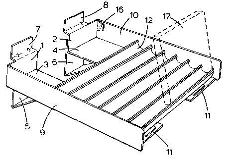
Figure 1 shows a complete shelf assembly according to the
present invention, and
Figure 2 shows a cutaway side view of a shelf mounted on a
slotted display wall.
DETAITT~n DESCRIPTION OF THE INVENTION
Referring now to the complete shelf assembly shown in
Figure 1, the assembly comprises brackets 1, 2 consisting of
narrow horizontal strap type arms 3, 4 provided with
symmetrically opposed side flanges 9, 10 which are turned up
sufficiently to protrude vertically, above the level of a shelf
12, supported on the arms, to act as end stops for the shelf as
shown in the drawing. The shelf 12 is secured on and between a
pair of such brackets by suitable means such as welding or, as
shown in the drawings, by adhesive strips 11. The use of
adhesive strips provides the advantage that a shelf can be
sized, i.e. cut to a desired length, and assembled to fit a
30 location where the shelf assembly is to be used. For instance, -~
the shelf can be sized to hold two compact disc cassettes, in
end to end relationship, in each horizontal slot 13 of the
shelf 12.
... , .
'~

~ 212S315
The brackets, at their inner, or wall, ends have their
inner end~ of the flat horizontal surface parts ,bent first
upward, then inward and then upwards again as shown clearly in ~ --
Figure 2, to provide a vertical, outset tabs 7, 8 which are
hooked into the T-slot of the slotted wall 14, Figure 2. This
is a common configuration for the inner ends of known brackets
provided for use with slotted walls. In order to provide
additional security of the shelf assembly, when mounted on a
wall 14, straps 4, bent to form an acute angle, may be fastened
to the outer sides of the bent up end portions of the
horizontal brackets to provide wide shoulders for wall contact
and extended angle braces for supporting the weight of a loaded
shelf. The angle parts may be secured to the straps 3, 4 by
spot welding, for instance. Furthermore, the bent up parts of f;.
the straps 3, 4 may be provided with tabs which are bent over
to attach to the upper part of the flanges 9, 10 as shown at 16
in Figure 2 to provide added rigidity.
Cassette holding shelves, or trays, 12 are available for
table or desk setting to hold cassettes in leaf-through
arrangement. For further information on the configuration of
the slots for the shelf elements, reference can be made to
Australian patent 327/26 and United States patent 4,819,813.
The manner in which the cassettes are held for leaf-through
arrangement is well known and not a feature of the present
nvention except as described in combination with the supporting
brackets forming the assembly according to the present
invention. I 3.~, "
Although a particular form of the invention has been
described herein, it should be understood that modifications
may be made in the construction of the assembly which do not
depart from the scope and spirit of the present invention as
defined by the amended claims. For, instance, the
configuration of the brackets may be varied by strengthening
:, . ~ ';' .

2125315
"
ribs or flanges. It is possible to dispense with the underside
bracing of the hori~ontal strap part of the bracket arms by
strengthening the bracket arms per se, f or instance, by
extending the f langes thereof and extending the wall resting
shoulder downward so as to provide good wall contact and
support for the bracket arm.
'~.

Representative Drawing
A single figure which represents the drawing illustrating the invention.
Administrative Status

2024-08-01:As part of the Next Generation Patents (NGP) transition, the Canadian Patents Database (CPD) now contains a more detailed Event History, which replicates the Event Log of our new back-office solution.

Please note that "Inactive:" events refers to events no longer in use in our new back-office solution.

For a clearer understanding of the status of the application/patent presented on this page, the site Disclaimer , as well as the definitions for Patent , Event History , Maintenance Fee  and Payment History  should be consulted.

Event History

Description Date
Inactive: IPC from MCD 2006-03-11
Time Limit for Reversal Expired 2001-06-07
Letter Sent 2000-06-07
Inactive: Late MF processed 1999-09-13
Letter Sent 1999-06-07
Inactive: Late MF processed 1998-07-13
Letter Sent 1998-06-08
Grant by Issuance 1997-04-08
Application Published (Open to Public Inspection) 1995-02-13
All Requirements for Examination Determined Compliant 1994-11-21
Request for Examination Requirements Determined Compliant 1994-11-21

Abandonment History

There is no abandonment history.

Maintenance Fee

The last payment was received on 

Note : If the full payment has not been received on or before the date indicated, a further fee may be required which may be one of the following

  • the reinstatement fee;
  • the late payment fee; or
  • additional fee to reverse deemed expiry.

Please refer to the CIPO Patent Fees web page to see all current fee amounts.

Fee History

Fee Type Anniversary Year Due Date Paid Date
MF (patent, 3rd anniv.) - small 1997-06-09 1997-06-05
MF (patent, 4th anniv.) - small 1998-06-08 1998-07-13
Reversal of deemed expiry 1999-06-07 1998-07-13
Reversal of deemed expiry 1999-06-07 1999-09-13
MF (patent, 5th anniv.) - small 1999-06-07 1999-09-13
MF (application, 2nd anniv.) - small 02 1996-06-07
Owners on Record

Note: Records showing the ownership history in alphabetical order.

Current Owners on Record
ULF ERNETOFT
Past Owners on Record
None
Past Owners that do not appear in the "Owners on Record" listing will appear in other documentation within the application.
Documents

To view selected files, please enter reCAPTCHA code :


To view images, click a link in the Document Description column. To download the documents, select one or more checkboxes in the first column and then click the "Download Selected in PDF format (Zip Archive)" or the "Download Selected as Single PDF" button.

List of published and non-published patent-specific documents on the CPD .

If you have any difficulty accessing content, you can call the Client Service Centre at 1-866-997-1936 or send them an e-mail at CIPO Client Service Centre.


Document
Description 
Date
(yyyy-mm-dd) 
Number of pages   Size of Image (KB) 
Claims 1997-03-03 2 64
Cover Page 1997-03-03 1 13
Description 1997-03-03 4 136
Abstract 1997-03-03 1 31
Drawings 1997-03-03 1 34
Cover Page 1995-05-20 1 48
Claims 1995-05-20 2 67
Abstract 1995-05-20 1 27
Drawings 1995-05-20 1 30
Description 1995-05-20 4 136
Representative drawing 1998-05-23 1 21
Maintenance Fee Notice 1998-07-06 1 179
Late Payment Acknowledgement 1998-07-15 1 172
Maintenance Fee Notice 1999-07-05 1 179
Late Payment Acknowledgement 1999-09-16 1 172
Maintenance Fee Notice 2000-07-05 1 178
Fees 1999-09-13 1 27
Fees 1997-06-05 1 33
Fees 1998-07-13 1 40
Prosecution correspondence 1994-06-07 6 418
Prosecution correspondence 1994-11-25 4 248
Courtesy - Office Letter 1995-01-25 1 53
Prosecution correspondence 1994-11-25 1 45
Maintenance fee correspondence 1997-01-31 1 35