Language selection

Search

Patent 2125340 Summary

Third-party information liability

Some of the information on this Web page has been provided by external sources. The Government of Canada is not responsible for the accuracy, reliability or currency of the information supplied by external sources. Users wishing to rely upon this information should consult directly with the source of the information. Content provided by external sources is not subject to official languages, privacy and accessibility requirements.

Claims and Abstract availability

Any discrepancies in the text and image of the Claims and Abstract are due to differing posting times. Text of the Claims and Abstract are posted:

  • At the time the application is open to public inspection;
  • At the time of issue of the patent (grant).
(12) Patent: (11) CA 2125340
(54) English Title: COMPRESSOR
(54) French Title: COMPRESSEUR
Status: Expired and beyond the Period of Reversal
Bibliographic Data
(51) International Patent Classification (IPC):
  • F04B 1/146 (2020.01)
  • F01B 3/04 (2006.01)
  • F04B 27/10 (2006.01)
(72) Inventors :
  • MURAKAMI, KAZUO (Japan)
  • KAWAGUCHI, MASAHIRO (Japan)
  • GOTO, KUNIFUMI (Japan)
(73) Owners :
  • KABUSHIKI KAISHA TOYODA JIDOSHOKKI SEISAKUSHO
(71) Applicants :
  • KABUSHIKI KAISHA TOYODA JIDOSHOKKI SEISAKUSHO (Japan)
(74) Agent: LAVERY, DE BILLY, LLP
(74) Associate agent:
(45) Issued: 1999-03-02
(22) Filed Date: 1994-06-07
(41) Open to Public Inspection: 1994-12-09
Examination requested: 1994-06-07
Availability of licence: N/A
Dedicated to the Public: N/A
(25) Language of filing: English

Patent Cooperation Treaty (PCT): No

(30) Application Priority Data:
Application No. Country/Territory Date
5-137836 (Japan) 1993-06-08

Abstracts

English Abstract


A double-headed tupe compressor has a disk plate. The disk
plate is rotatably supported on a drive shaft for driving each
piston along a reciprocating path. The plate is curved in a
single direction to form a solid cam on its surface. The cam
transforms a single rotation of the plate into two
reciprocating movements of the piston. Cam followers provided
between the plate and the piston are formed to be comformable
to the cam. The cam followers contact and roll on the piston,
and slide on the cam.


French Abstract

Compresseur, muni de pistons à deux têtes, comprenant un plateau sous forme de disque. Ce dernier est soutenu de manière à tourner sur un arbre d'entraînement pour entraîner chaque piston le long d'une course alternative. Le plateau est courbé dans une direction unique afin de former une came solide sur sa surface. La came transforme une rotation unique du plateau en deux déplacements alternatifs du piston. Les galets suiveurs, situés entre le plateau et le piston, sont formés de façon à épouser la forme de la came. Ils entrent en contact avec le piston et roulent dessus, puis glissent sur la came.

Claims

Note: Claims are shown in the official language in which they were submitted.

CLAIMS
1. A compressor comprising a cam member
rotatably supported on a drive shaft for driving a piston
along a reciprocating path defined by a top dead center
and a bottom dead center of the piston stroke, wherein a
single rotation of said cam member causes two
reciprocating movements of the piston, said cam member
being cylindrically shaped and having a pair of
oppositely facing cam surfaces: said piston including a
pair of recesses opposed to each other, each recess
having a concave bottom surface; and
a first cam follower and second cam follower
respectively interposed between the cam surfaces and the
piston to transmit the rotation of the cam member to the
piston, each cam follower having a sliding contact
surface conforming in shape to its said respective cam
surface for sliding on said respective cam surface and
having a convex rolling surface for rolling on the
concave bottom surface of one of said recesses.
2. A compressor as set forth in Claim 1,
wherein said cam member includes a plate that forms a
part of a cylinder and said cam member has a convex
surface and a concave surface.
3. A compressor as set forth in Claim 2,
wherein said plate has two end portions and a middle
- 9 -

portion for driving the piston to the upper dead center
and to the lower end center, respectively.
4. A compressor as set forth in Claim 2,
wherein said piston has a pair of recesses opposed to
each other, each recess having a concave bottom surface,
and wherein said transmitting means includes a first and
second cam followers, each cam follower having a convex
rolling surface for rolling on the convex bottom surface
of the recess.
5. A compressor as set forth in Claim 3,
wherein said first cam follower has a concave contact
surface in conformity with the convex surface of the cam
member, and said second cam follower has a convex contact
surface in conformity with the first concave surface of
the cam member.
6. A compressor as set forth in Claim 4,
wherein each contact surface contacts and slides on the
associated surface of the cam member for the entire range
of the contact surface.
7. A compressor having a disk plate rotatably
supported by a drive shaft for driving a double-headed
piston along a reciprocating path defined by a top dead
center and a bottom center of a stroke of the piston,
wherein a single rotation of said plate causes two
- 10 -

reciprocating movements of the piston, said compressor
comprising:
a cam member provided for the plate and curved
in a single direction, said cam member having a convex
surface and a concave surface;
said piston having a pair of recesses opposed
to each other, wherein each recess has a concave bottom
surface;
a first and a second cam followers interposed
between the cam member and the piston, each cam follower
having a convex rolling surface for rolling on the convex
bottom surface of the piston recess; and
said first cam follower having a concave
contact surface in conformity with the convex surface of
the cam member, and a convex contact surface in
conformity with the concave surface of the cam member,
wherein each contact surface contacts and slides on the
associated surface of the cam member with the entire
range of the contact surface.
8. A compressor as set forth in Claim 7,
wherein said plate forms a part of a cylinder.
9. A compressor as set forth in Claim 7,
wherein said plate has two end portions and a middle
portion for driving the piston to the upper dead center
and to the lower end center, respectively.
- 11 -

10. A compressor for the use in a vehicle,
having a solid cam disk operably linked to a plurality of
double-headed pistons, said cam disk being supported on
a rotary drive shaft for the integral rotation therewith,
wherein a single rotation of the disk causes a plurality
of reciprocating movements of each piston, said
compressor comprising:
said cam disk being curved in a single
direction and having a convex surface and a concave
surface, respectively;
each piston having a pair of recesses opposed
to each other, wherein each recess has a concave bottom
surface;
a first and a second cam followers, each cam
follower having a convex rolling surface for rolling on
the convex bottom surface of the piston recess; and
said first cam follower having a concave
contact surface in conformity with the convex surface of
the cam disk, and a convex contact surface in conformity
with the concave surface of the cam disk, wherein each
contact surface contacts and slides on the associated
surface of the cam disk for the entire range of the
contact surface.
11. A compressor as set forth in Claim 10,
wherein said plate has two end portions and a middle
portion for driving the piston to the upper dead center
and to the lower end center, respectively.
- 12 -

Description

Note: Descriptions are shown in the official language in which they were submitted.


CA 0212~340 1998-09-03
COMPRESSOR
BACKGROUND OF THE lNv~NllON
Field of the Invention
The present invention relates to a compressor and more
particularly to a compressor in which oscillating pistons
reciprocate due to the rotation of a cam surfaced plate
secured around a drive shaft.
Description of the Related Art
In compressors having double-headed pistons that reciprocate
in associated cylinder bores by the rotating action of a swash
plate, each piston reciprocates only once for each complete
revolution the swash plate makes. One way to increase the
compressor's compression displacement per rotation of the
swash plate, is to design larger sized compressors. Since
compressors are often mounted in vehicles, however, their
large design is distinctly undesirable.
One proposed solution to the above shortcoming is the recently
developed wave plate type compressor disclosed in Japanese
Unexamined Patent Publication No. 57-110783. In this
compressor, the swash plate is replaced with a plate having
the shape of a solid cam. This cam is a disk-shaped plate
--1--

CA 0212~340 1998-09-03
having circumferentally extending undulating surfaces formed
on the plate. If the wave plate has two undulations i.e., two
crests and two troughs, each double-headed piston performs two
compressing actions for each turn the wave plate makes. It
is therefore possible to increase the compression displacement
without enlarging the compressor.
To manufacture the wave shaped dish of this type of
compressor, the dish must be formed with undulations in the
circumferential direction, and its wavy cam surfaces should
be polished. It is very difficult, however, to form and
polish the undulated surfaces with any high degree of
precision. Consequently, the manufacture of such a compressor
containing these types of plates has proven quite difficult.
Since the crest and trough of the undulated cam surface have
inverse curvatures, it is as yet not possible to form cam
followers having shapes that accurately correspond to the
crests and troughs of the undulated cam surface. The type of
surface contact shared between the cam surface and the cam
follower is a point or line contact, rather than a plane
contact. This construction precludes there being any large
or significant amount of contact area shared between the cam
surface and the cam follower. Consequently, both cam surface
and follower are subject to a large contact pressure per unit
area. Such pressure tends to cause the premature wearing of
the cam surface and cam follower, and thus decreases the
--2--

CA 0212~340 1998-09-03
longevity and effective service life of the compressor. This
premature wearing also tends to facilitate the generation of
vibration and noise in the compressor during its operation,
degrading the overall smooth operation and operating
environment of the compressor.
SUMMARY OF THE lNv~NllON
Accordingly, it is a primary objective of the present
invention to provide a compressor which can be manufactured
easily.
It is another objective of the present invention to provide
a compressor which has a prolonged service life.
It is a further objective of the present invention to provide
a compressor which can suppress noise and vibration and can
be used comfortably.
To achieve those objectives, according to the present
invention, a compressor has a disk plate rotatably supported
on a drive shaft for driving a double-headed piston along a
reciprocating path defined by a top dead center and a bottom
center of a stroke of the piston. A single rotation of said
plate causes two reciprocating movements of the piston. A cam
member is provided with the plate. The cam member being
curved in a single direction. Cam followers are interposed
--3--

CA 0212~340 1998-09-03
between the cam member and the plate for transmitting the
rotation of the plate to the piston.
BRIEF DESCRIPTION OF THE DRAWINGS
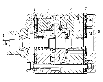
Fig. 1 is a side cross-sectional view showing an overall
compressor according to one embodiment of the present
invention;
Fig. 2 is a cross sectional view of the compressor taken along
the line A-A in Fig. 1;
Fig. 3 is a partially cross-sectional view of the compressor;
and
Fig. 4 is a perspective view schematically showing a wave
plate.
DETATT.~n DESCRIPTION OF THE PR~r~KK~ EMBODIMENT
One embodiment of the present invention will now be described
referring to the accompanying drawings.
As shown in Fig. 1, a shaft 3 is rotatably supported in a pair
of cylinder blocks 1 and 2 which are secured to each other.
A disk plate 4 having the shape of a solid cam is secured on
the shaft 3. Plural pairs of front cylinder bores la and rear
--4--

CA 0212~340 1998-09-03
cylinder bores 2a are respectively formed and arranged in the
cylinder blocks 1 and 2 at equiangular distances. Double-
headed pistons 5 are slidably inserted in the associated
cylinder bores la and 2a.
A front housing 8 and a rear housing 9 are arranged at the
outer end surfaces of the cylinder blocks 1 and 2 via valve
plates 6 and 7. The housings 8 and 9 and the cylinder blocks
1 and 2 are securely fastened together by bolts 10. Suction
chambers 13 and 14 and discharge chambers 15 and 16 are
respectively defined in the housings 8 and 9. The suction
chambers 13 and 14 communicate with a plate chamber 12 and
communicate via inlet valves 20 with the cylinder bores la and
2a. The discharge chambers 15 and 16 communicate via
discharge valves 21 with the cylinder bores la and 2a. The
plate chamber 12 is coupled to the outlet port of the
evaporator (not shown) of a refrigerating circuit.
As shown in Fig. 4, the plate 4 has the shape of a circular
part cut out of an imaginary cylinder P with an axis Y as the
center. The plate 4 has cam surfaces S1 and S2 at the top and
bottom. More specifically, the cam surface S1 has a concave
surface with a uniform curvature, and the other cam surface
S2 has a convex surface with a uniform curvature.
Accordingly, the cam surfaces S1 and S2 of the plate 4 are
curved in one direction and are located on the concentrical
cylindrical surfaces about the axis Y.
--5--

CA 0212~340 1998-09-03
Each piston 5 has a pair of spherical recesses 5a formed
facing the respective cam surfaces S1 and S2 of the plate 4,
as shown in Figs. 1 and 3. Shoes 23 and 24 as cam followers
are supported in the recesses 5a in order to allow their
spherical surfaces 23a and 24a to rotate. The shoes 23 and
24 are formed with sliding surfaces 23b and 24b which engage
with the cam surfaces S1 and S2 of the plate 4. More
specifically, the shoe 23, with its convex sliding surface
23b, is engaged with the concave cam surface S1. Similarly
the shoe 24, with its concave sliding surface 24b, is engaged
with the convex cam surface S2. The sliding surfaces 23b and
24b have the same curvatures as the cam surfaces Sl and S2
that contact the former surfaces 23b and 24b.
The function of the thus constituted compressor will now be
described.
As the shaft 3 rotates, the plate 4 turns. Due to the cam
function of the plate 4, each double-headed piston 5
reciprocates in the associated cylinder bores la and 2a via
the shoes 23 and 24 to effect the suction, compression and
discharge of a fluid. Each piston 5 reaches the top dead
center in the cylinder bores la and 2a at the respective end
portions in the diametric direction and reaches the bottom
dead center at the center portion. The piston 5 therefore has
a two-cycle movement, which provides the same advantages as
the conventional wave plate type compressor. At this time,
--6--

CA 0212~340 1998-09-03
as the plate 4 turns, the shoes 23 and 24 change their
directions to always face the associated cam surfaces S1 and
S2 in the axial direction of the imaginary cylinder P. soth
the shoes 23 and 24 slide with respect to the cam surfaces S1
and S2 without changing their direction.
In this case, the sliding surfaces 23b and 24b of the shoes
23 and 24 have the same curvatures as the associated cam
surfaces S1 and S2. The shoes 23 and 24 therefore come in a
plane contact with the associated planar surfaces of cam S1
and S2. More specifically, the cam surfaces S1 and S2 are the
surfaces of an imaginary cylinder about an axis, so that the
curvatures are uniform over the entire surfaces. If the
curvatures of the sliding surfaces 23b and 24b of the shoes
23 and 24 are set equal to those of the cam surfaces S1 and
S2, the aforementioned planar contact can be established. It
is thus possible to reduce the contact pressure per unit area
and prevent early wearing of the cam surfaces S1 and S2 and
the shoes 23 and 24. This prolongs the longevity and service
life of the compressor. It is also possible to prevent or
greatly reduce the occurrence of vibrations and generation of
noise during the compressor's operation. This enhances the
compressor's smooth operation and overall operating
environment.
As mentioned earlier, the disk should be curved in one
direction so that the plate 4 forms a part of an imaginary
--7--

CA 0212~340 1998-09-03
cylinder. It is thus easier to form the plate 4 than the
conventional type which contains a plurality of
circumferentially extending undulations. In addition, since
the cam surfaces S1 and S2 have a uniform curvature over their
entire surfaces, they can easily be polished unlike in the
case with the undulated plate. The ease of forming and
accurately polishing the plate 4 of this embodiment, makes its
production and manufacture much simpler than with plates
having a conventional design.

Representative Drawing
A single figure which represents the drawing illustrating the invention.
Administrative Status

2024-08-01:As part of the Next Generation Patents (NGP) transition, the Canadian Patents Database (CPD) now contains a more detailed Event History, which replicates the Event Log of our new back-office solution.

Please note that "Inactive:" events refers to events no longer in use in our new back-office solution.

For a clearer understanding of the status of the application/patent presented on this page, the site Disclaimer , as well as the definitions for Patent , Event History , Maintenance Fee  and Payment History  should be consulted.

Event History

Description Date
Inactive: IPC removed 2024-06-18
Inactive: First IPC assigned 2024-06-18
Inactive: IPC assigned 2024-06-18
Inactive: IPC expired 2020-01-01
Inactive: IPC from MCD 2006-03-11
Time Limit for Reversal Expired 2003-06-09
Letter Sent 2002-06-07
Grant by Issuance 1999-03-02
Pre-grant 1998-11-12
Inactive: Final fee received 1998-11-12
Inactive: Received pages at allowance 1998-09-03
Letter Sent 1998-08-10
Notice of Allowance is Issued 1998-08-10
Inactive: Application prosecuted on TS as of Log entry date 1998-08-05
Inactive: Status info is complete as of Log entry date 1998-08-05
Inactive: Approved for allowance (AFA) 1998-06-16
Application Published (Open to Public Inspection) 1994-12-09
Request for Examination Requirements Determined Compliant 1994-06-07
All Requirements for Examination Determined Compliant 1994-06-07

Abandonment History

There is no abandonment history.

Maintenance Fee

The last payment was received on 1998-05-19

Note : If the full payment has not been received on or before the date indicated, a further fee may be required which may be one of the following

  • the reinstatement fee;
  • the late payment fee; or
  • additional fee to reverse deemed expiry.

Please refer to the CIPO Patent Fees web page to see all current fee amounts.

Fee History

Fee Type Anniversary Year Due Date Paid Date
MF (application, 3rd anniv.) - standard 03 1997-06-09 1997-05-26
MF (application, 4th anniv.) - standard 04 1998-06-08 1998-05-19
Final fee - standard 1998-11-12
MF (patent, 5th anniv.) - standard 1999-06-07 1999-05-25
MF (patent, 6th anniv.) - standard 2000-06-07 2000-05-18
MF (patent, 7th anniv.) - standard 2001-06-07 2001-05-16
Owners on Record

Note: Records showing the ownership history in alphabetical order.

Current Owners on Record
KABUSHIKI KAISHA TOYODA JIDOSHOKKI SEISAKUSHO
Past Owners on Record
KAZUO MURAKAMI
KUNIFUMI GOTO
MASAHIRO KAWAGUCHI
Past Owners that do not appear in the "Owners on Record" listing will appear in other documentation within the application.
Documents

To view selected files, please enter reCAPTCHA code :


To view images, click a link in the Document Description column. To download the documents, select one or more checkboxes in the first column and then click the "Download Selected in PDF format (Zip Archive)" or the "Download Selected as Single PDF" button.

List of published and non-published patent-specific documents on the CPD .

If you have any difficulty accessing content, you can call the Client Service Centre at 1-866-997-1936 or send them an e-mail at CIPO Client Service Centre.


Document
Description 
Date
(yyyy-mm-dd) 
Number of pages   Size of Image (KB) 
Cover Page 1995-06-10 1 50
Abstract 1995-06-10 1 29
Claims 1995-06-10 4 198
Drawings 1995-06-10 4 148
Description 1995-06-10 8 392
Description 1998-09-03 8 235
Abstract 1998-09-03 1 14
Cover Page 1999-02-23 1 52
Claims 1998-05-27 4 125
Drawings 1998-05-27 4 68
Representative drawing 1999-02-23 1 19
Commissioner's Notice - Application Found Allowable 1998-08-10 1 166
Maintenance Fee Notice 2002-07-08 1 177
Correspondence 1998-08-06 1 98
Correspondence 1998-09-03 10 275
Correspondence 1998-11-12 1 36
Fees 1997-05-26 1 44
Fees 1998-05-19 1 47
Fees 1999-05-25 1 43
Maintenance fee payment 1996-05-22 1 56
Prosecution correspondence 1994-06-07 17 566
Prosecution correspondence 1998-09-03 1 27
Prosecution correspondence 1998-04-07 2 40
Examiner Requisition 1997-10-15 2 44
Prosecution correspondence 1997-07-18 2 55
Examiner Requisition 1997-01-21 2 73